Toyota 4Runner (1999 – 2000) – fuse box diagram
Year of production: 1999, 2000
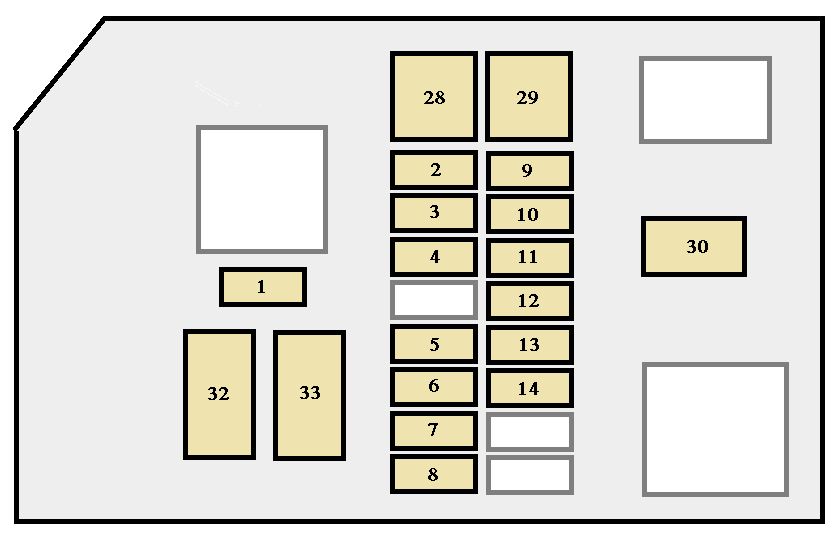
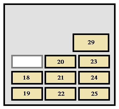
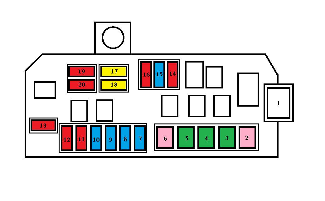
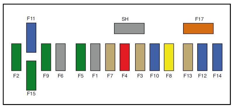
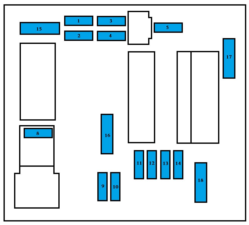
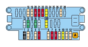
Engine compartment (U.S.A.)
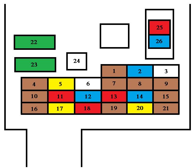
Engine compartment (Canada)
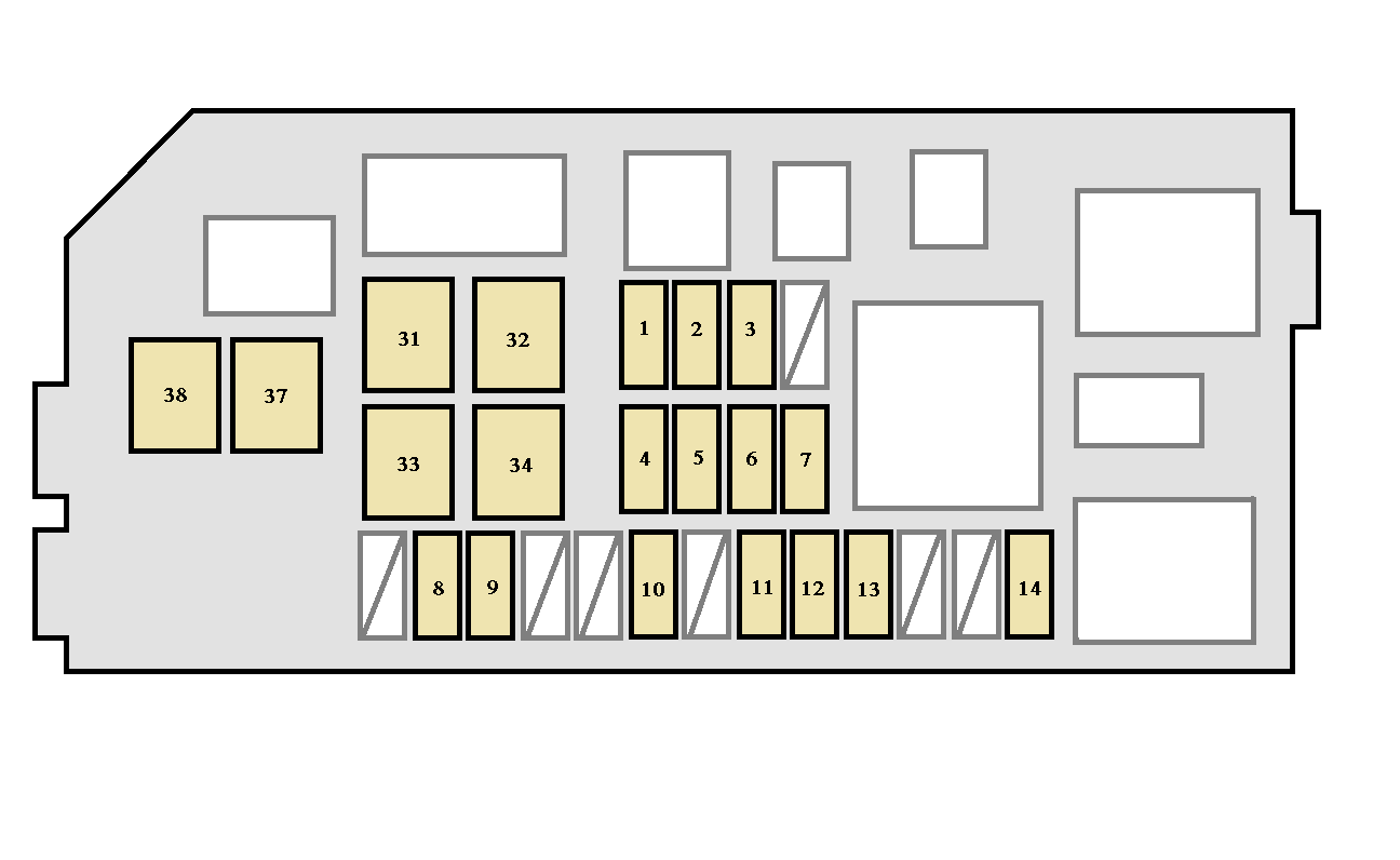
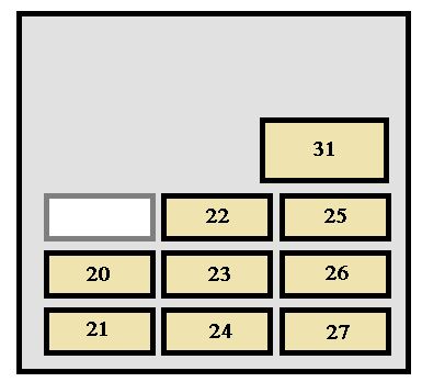
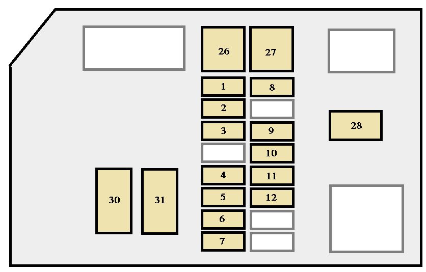
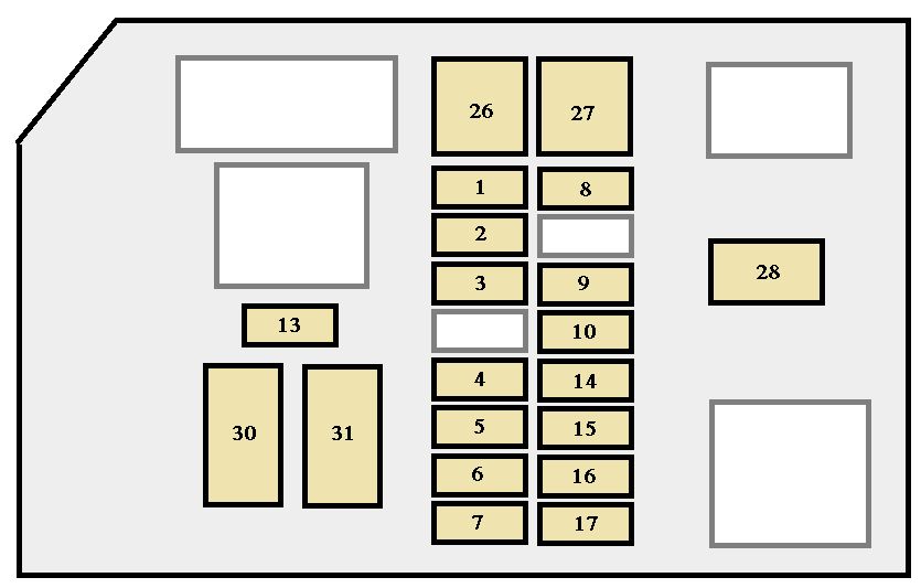
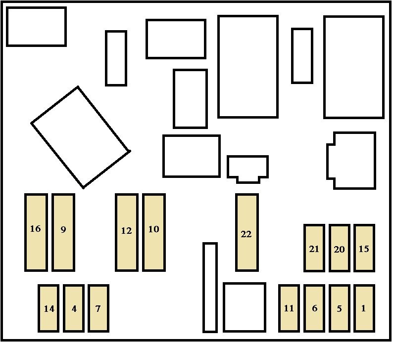
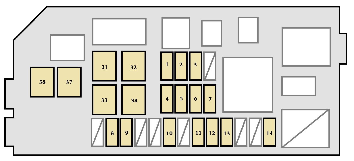
Instrument panel
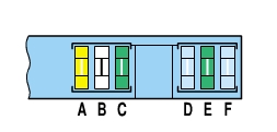
Fuse (type A)
| Fuse | Ampere rating [A] | Functions | |
| 1 | ALT-S | 7,5 | Charging system |
| 2 | PWR OUTLET | 15 | Power outlets |
| 3 | RR HTR | 10 | Rear air conditioning system |
| 4 | MPX- B | 15 | Power back window, back door lock, back window wiper, open door warning (back door), power door lock control system, back window defogger, horns, theft deterrent system |
| 5 | DOME | 15 | Interior lights, personal lights, luggage compartment light, clock, car audio system, gauges and meters, ignition switch light, vanity mirror light, daytime running light |
| 6 | OBD | 7,5 | On- board diagnosis system |
| 7 | EFI | 20 | Multiport fuel injection system/sequential multiport fuel injection system |
| 8 | HEAD(RH) | 10 | Right- hand headlight, gauges and meters |
| 9 | HEAD(LH) | 10 | Left- hand headlight |
| 10 | TAIL | 10 | Tail lights, license plate lights, instrument panel lights |
| 11 | A.C | 10 | Air conditioning control system |
| 12 | MIR HTR | 10 | Outside rear view mirror heaters |
| 13 | DEFOG | 15 | Back window defogger |
| 14 | FOG | 15 | Front fog lights |
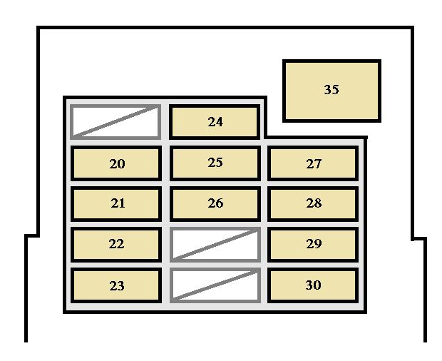
| 15 | DRL | 7,5 | Daytime running light system |
| 16 | HEAD (HI RH) | 10 | Right- hand headlight (high beam), gauges and meters |
| 17 | HEAD (HI LH) | 10 | Left-hand headlight (high beam) |
| 18 | HEAD (LO RH) | 10 | Right- hand headlight (low beam) |
| 19 | HEAD (LO LH) | 10 | Left- hand headlight (low beam) |
| 20 | ECU- IG | 10 | Cruise control system, anti- lock brake system, electronically controlled automatic transmission system, power antenna, power window, electric moon roof, power back window, back window defogger, back window wiper |
| 21 | TURN | 10 | Turn signals lights, emergency flashers |
| 22 | WIPER | 20 | Windshield wipers and washer, power door lock control system, back window defogger, horns, theft deterrent system |
| 23 | 4WD | 20 | A.D.D. control system, four- wheel drive control system, rear differential lock system |
| 24 | ACC | 15 | Car audio system, power antenna, clock, power rear view mirror control, cigarette lighter, SRS airbag system, seat belt pretensioners, electronically controlled automatic transmission system, power outlets, theft deterrent system |
| 25 | GAUGE | 10 | Gauges and meters, back window defogger, daytime running light system, air conditioning system, cruise control system, rear differential lock system, electronically controlled automatic transmission, back- up lights |
| 26 | IGN | 10 | SRS airbag system, seat belt pretensioners, multiport fuel injection system/sequential multiport fuel injection system, discharge warning light |
| 27 | ECU-B | 7,5 | Gauges and meters, SRS airbag system, seat belt pretensioners |
| 28 | HORN,HAZ | 15 | Horns, emergency flashers |
| 29 | STA | 7,5 | Starting system |
| 30 | STOP | 10 | Stop lights, high- mounted stoplight |
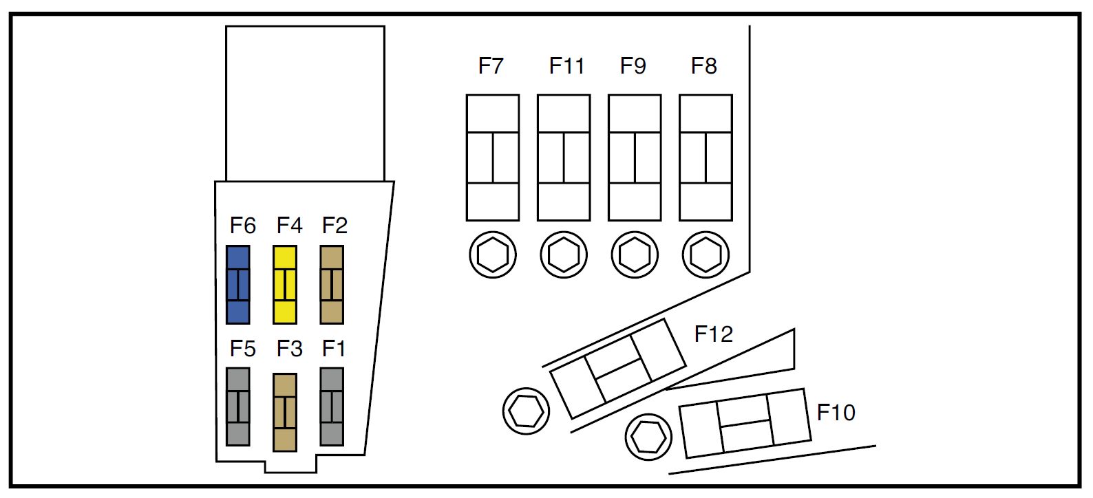
Fuses (type B)
| Fuse | Ampere rating [A] | Functions | |
| 31 | HEATER | 50 | Air conditioning system, all components in ”A.C” fuse |
| 32 | AM1 | 40 | Starting system, all components in ”ACC”, ”GAUGE”, ”TURN”, ”ECU- IG”, ”WIPER”, ”4WD” fuses |
| 33 | J/B | 50 | All components in ”POWER”, ”HORN,HAZ”, ”STOP”, ”ECU- B” fuses |
| 34 | AM2 | 30 | Starting system, multiport fuel injection system/sequential multiport fuel injection system, all components in ”STA”, ”IGN” fuses |
| 35 | POWER | 30 | Power window, power back window, electric moon roof, power seat, back door lock |
Fuses (type C)
| Fuse | Ampere rating [A] | Functions | |
| 36 | ABS | 60 | Anti- lock brake system |
| 37 | ALT | 120 | Charging system, all components in ”AM1”, ”HEATER”, ”TAIL”, ”RR HTR”, ”ALT- S”, ”DEFOG”, ”MIR HTR” and ”ACC” fuses |
WARNING: Terminal and harness assignments for individual connectors will vary depending on vehicle equipment level, model, and market.