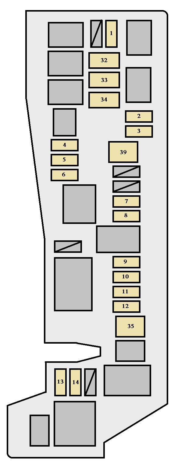
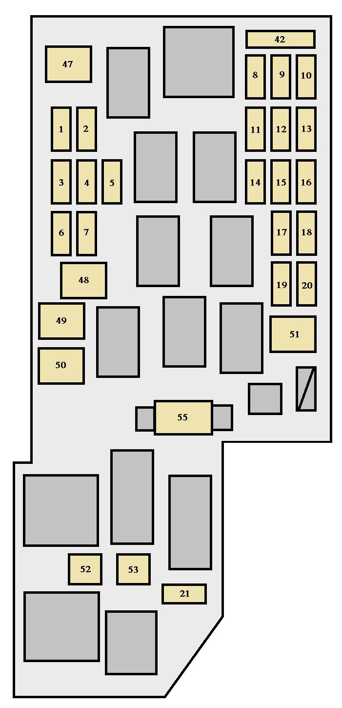
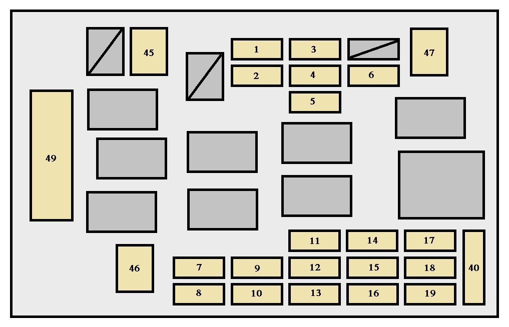
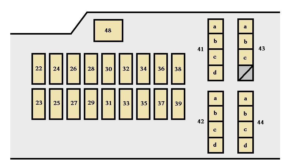
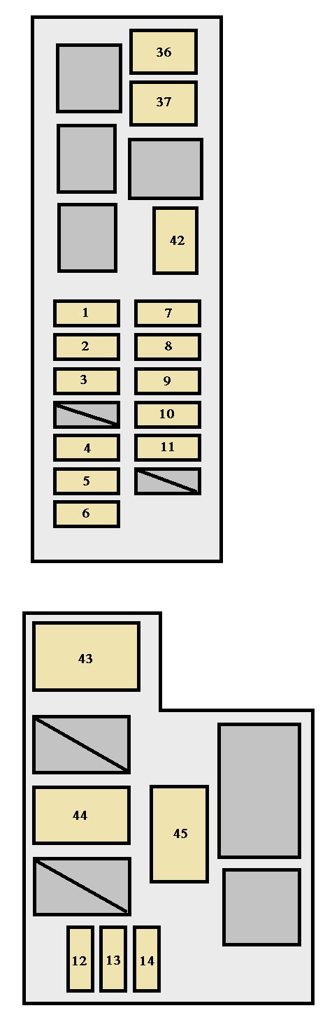
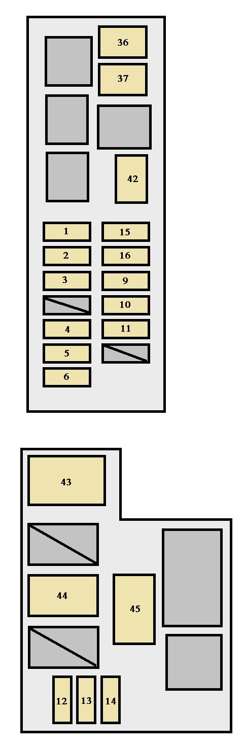
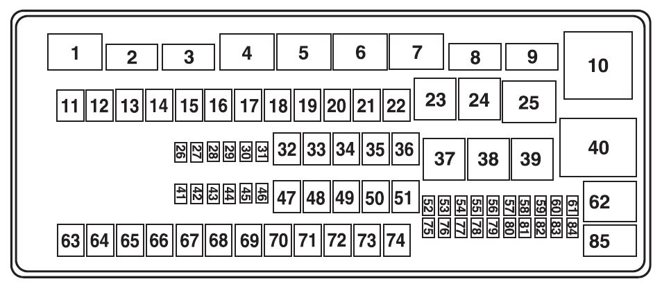
| Fuse/relay location |
Ampere rating [A] |
Protected Circuits |
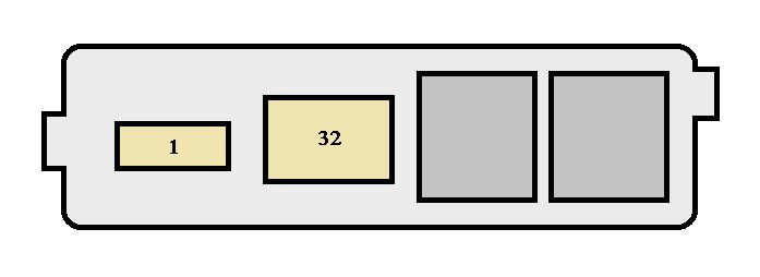
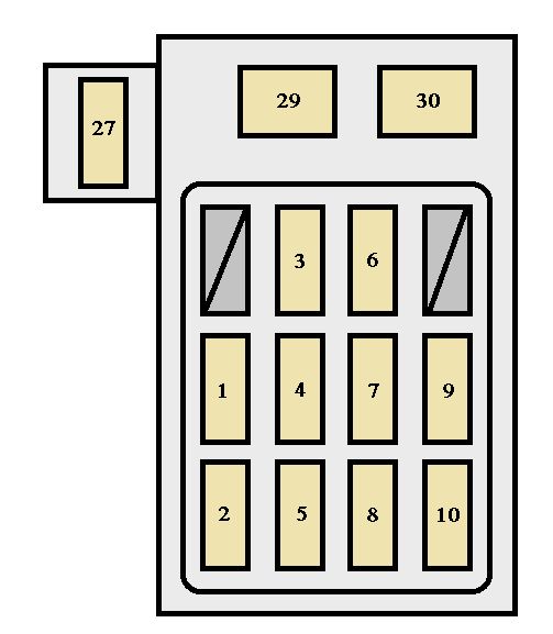
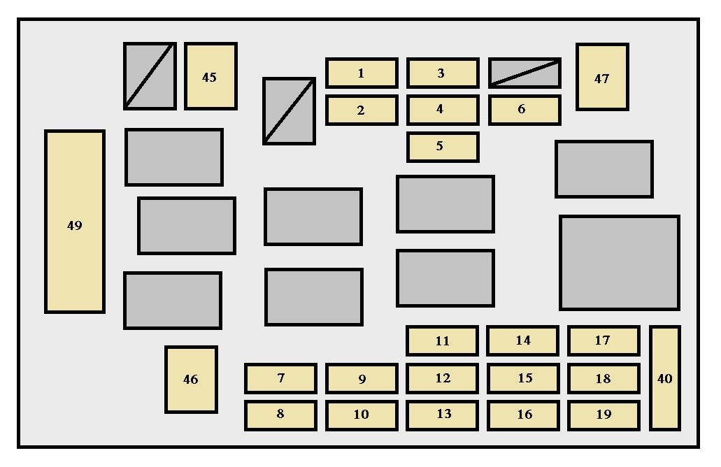
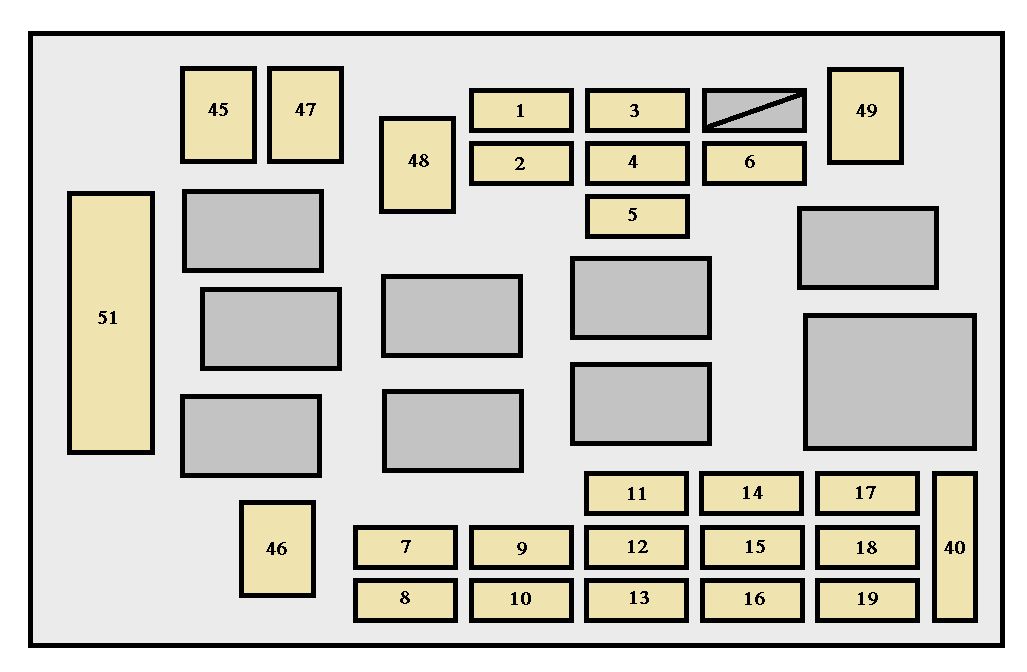
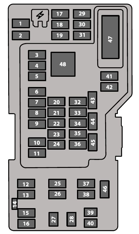
| 1 |
— |
Powertrain control module relay. |
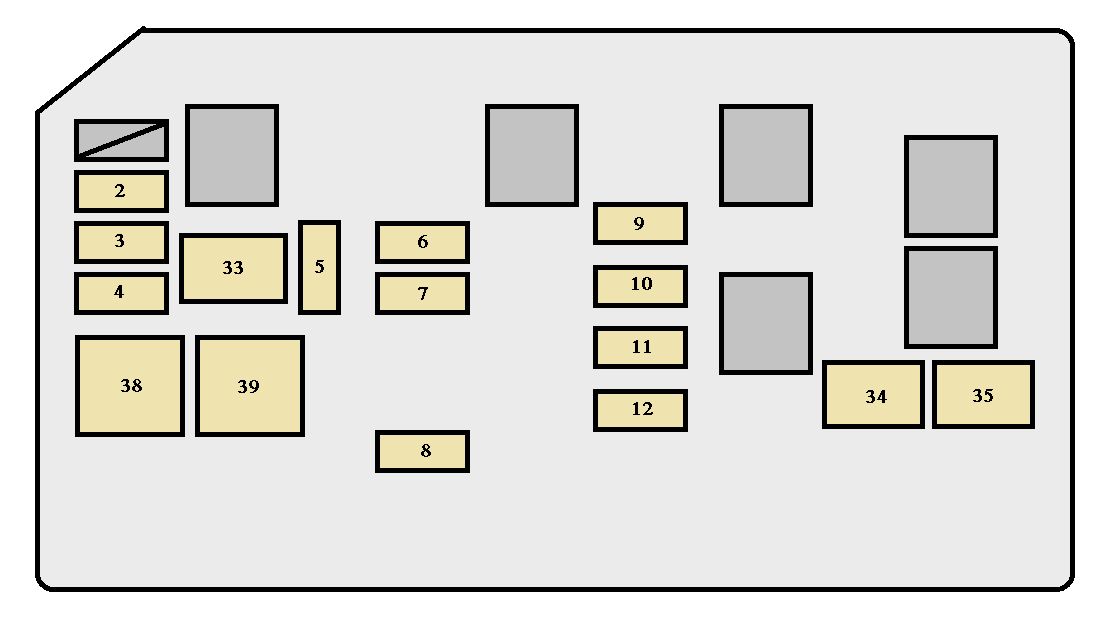
| 2 |
— |
Starter solenoid relay. |
| 3 |
— |
Wiper relay |
| 4 |
— |
Trailer tow battery charge |
| 5 |
— |
Fuel pump relay |
| 6 |
— |
Trailer tow park lamp relay |
| 7 |
— |
Auxiliary switch #4 relay |
| 8 |
— |
Auxiliary switch #4 relay |
| 9 |
— |
Modified vehicle and stripped chassis run/start relay |
| 10 |
— |
Not used |
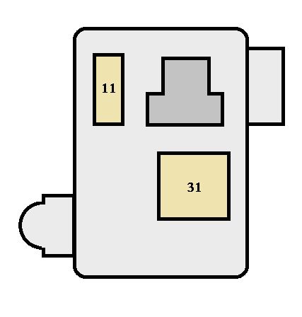
| 11 |
— |
Not used |
| 12 |
40** |
Modified vehicle and stripped chassis run/start |
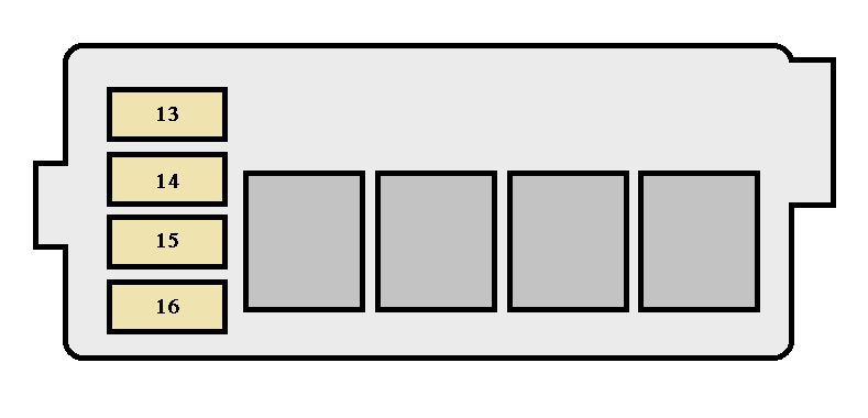
| 13 |
30** |
Starter solenoid relay |
| 14 |
40** |
Run start relay |
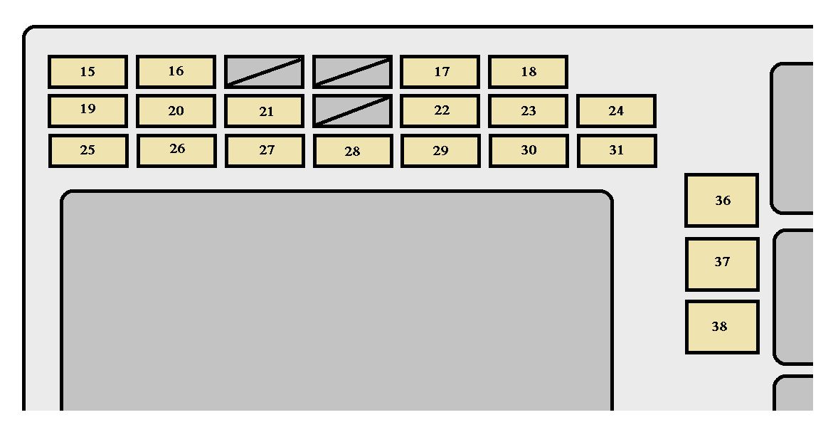
| 15 |
40** |
Modified vehicle and stripped chassis battery |
| 16 |
50** |
Auxiliary air conditioning blower |
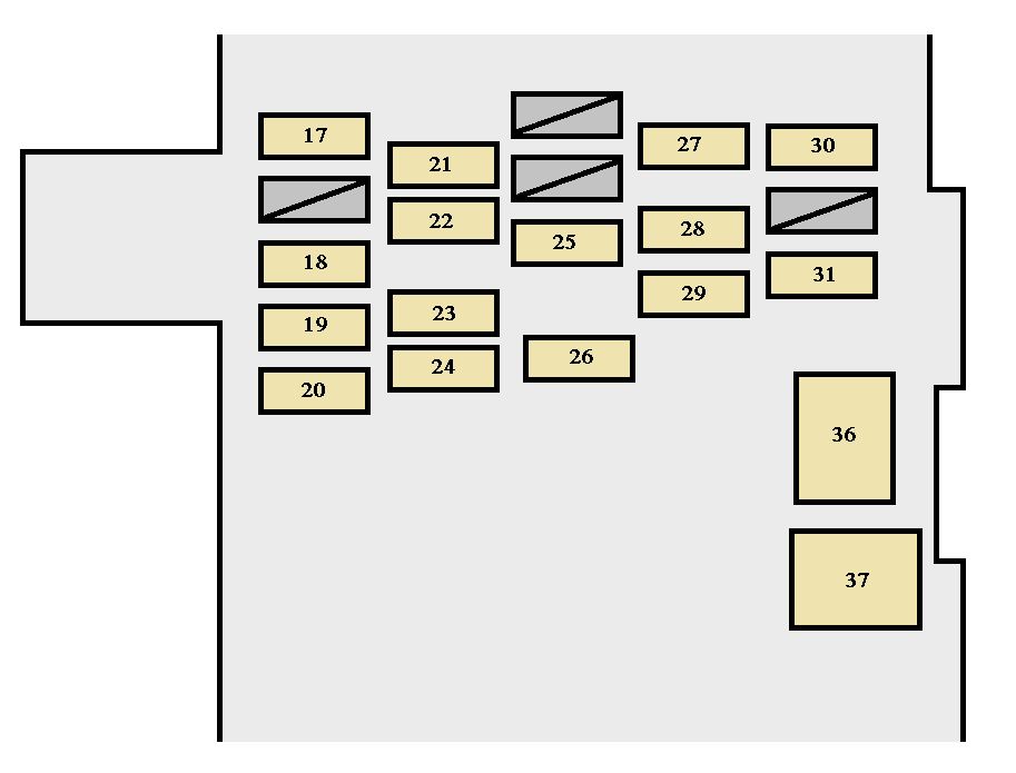
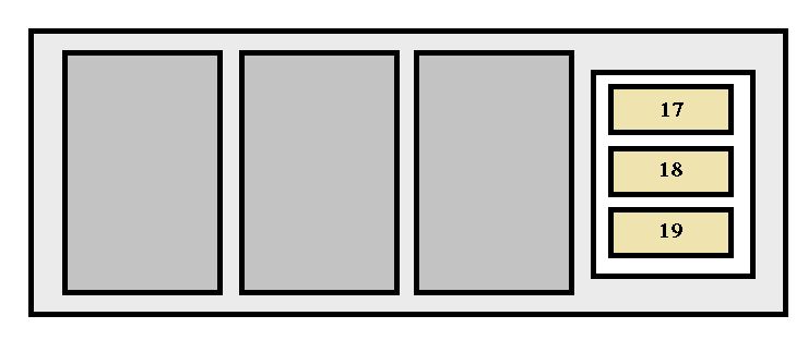
| 17 |
50** |
Trailer tow battery charge, trailer tow park feed |
| 18 |
30** |
Electric trailer brake, Trailer brake controller |
| 19 |
30** |
Auxiliary switch #1 |
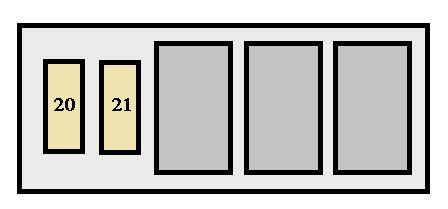
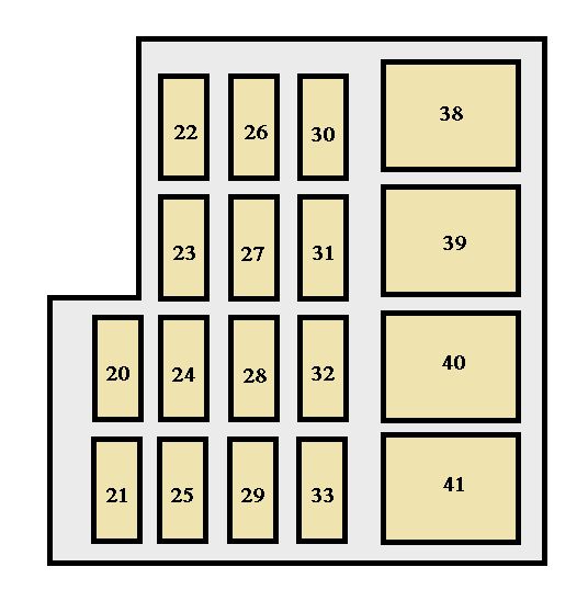
| 20 |
30** |
Auxiliary switch #2 |
| 21 |
50** |
Not used |
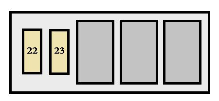
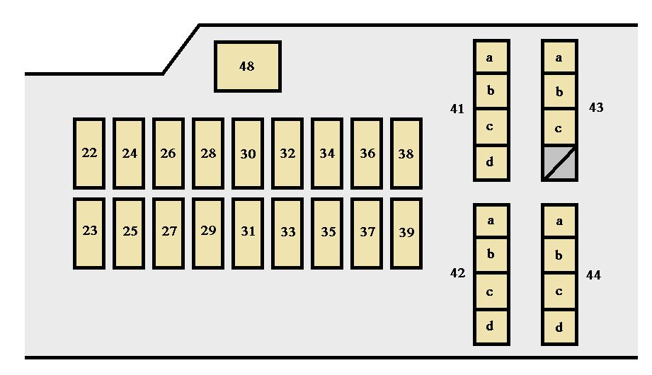
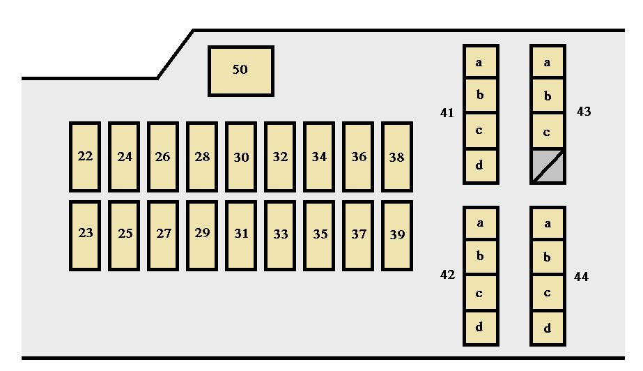
| 22 |
— |
Not used |
| 23 |
— |
Air conditioning clutch |
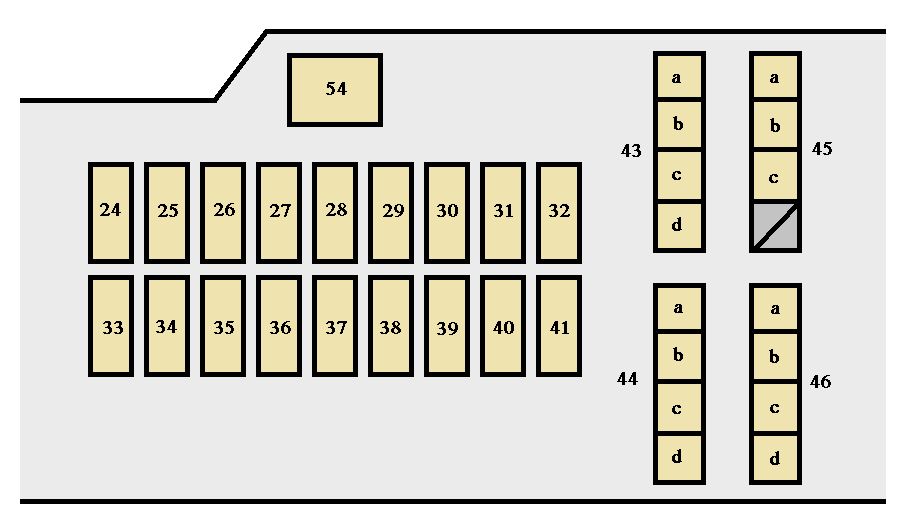
| 24 |
— |
Horn relay (Stripped chassis) |
| 25 |
— |
Run/start relay |
| 26 |
— |
Not used |
| 27 |
— |
Not used |
| 28 |
20* |
Back up lamp |
| 29 |
10* |
Air conditioning clutch |
| 30 |
10* |
Brake on/off (BOO) switch |
| 31 |
10* |
Cluster battery (stripped chassis only) |
| 32 |
50** |
Blower motor |
| 33 |
40** |
Anti-lock brake system (ABS) pump |
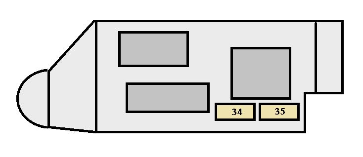
| 34 |
20** |
Stripped chassis horn |
| 35 |
40** |
Powertrain control module relay |
| 36 |
20** |
Ignition switch (Stripped chassis only) |
| 37 |
— |
Trailer tow left-hand side stop lamp and direction indicator lamp relay |
| 38 |
— |
Trailer tow right-hand side stop lamp and direction indicator lamp relay |
| 39 |
— |
Back-up lamp relay |
| 40 |
— |
Blower motor relay |
| 41 |
— |
Not used |
| 42 |
15* |
Diagnostic connector (stripped chassis) |
| 43 |
20* |
Fuel pump |
| 44 |
10* |
Auxiliary switch #3 |
| 45 |
15* |
Auxiliary switch #4 |
| 46 |
10* |
Powertrain control module keep alive power, Canister vent, Powertrain control module relay coil |
| 47 |
40** |
Anti-lock brake system coil |
| 48 |
20** |
Trailer tow stop lamp/turn signal |
| 49 |
30** |
Wiper motor |
| 50 |
— |
Not used |
| 51 |
20** |
Cutaway |
| 52 |
10* |
Modified vehicle and stripped chassis run/start relay coil |
| 53 |
10* |
Anti-lock brake system run/start feed |
| 54 |
10* |
Fuel pump relay coil |
| 55 |
— |
Not used |
| 56 |
— |
Not used |
| 57 |
20* |
Trailer tow park lamp |
| 58 |
15* |
Trailer tow backup lamp |
| 59 |
— |
Not used |
| 60 |
— |
One touch integrated start (OTIS) (diode) |
| 61 |
— |
Not used |
| 62 |
— |
Auxiliary switch #2 relay |
| 63 |
30** |
Trailer tow battery charge |
| 64 |
— |
Not used |
| 65 |
20** |
Power point 2 (glove box) |
| 66 |
20** |
Power point 3 (cutaway B+) |
| 67 |
20** |
Power point 1 (instrument panel) |
| 68 |
50** |
Modified vehicle |
| 69 |
— |
Not used |
| 70 |
30** |
Stripped chassis |
| 71 |
— |
Not used |
| 72 |
20** |
Cigar lighter / Power point |
| 73 |
— |
Not used |
| 74 |
30* |
Power seat |
| 75 |
20* |
Vehicle power 1, Powertrain control module power |
| 76 |
20* |
Vehicle power 2, Powertrain control module – emission related powertrain components |
| 77 |
10* |
Vehicle power 3, Powertrain control module – general powertrain components |
| 78 |
15* |
Vehicle power 4, Engine ignition coil relay coil |
| 79 |
10* |
Vehicle power 5, Transmission |
| 80 |
10* |
Cluster run/start (stripped chassis only) |
| 81 |
— |
Not used |
| 82 |
— |
Not used |
| 83 |
— |
Fuel pump (diode) |
| 84 |
— |
Not used |
| 85 |
— |
Auxiliary switch #1 relay |
| * Mini fuses
** A1S fuses
***Cartridge fuses |