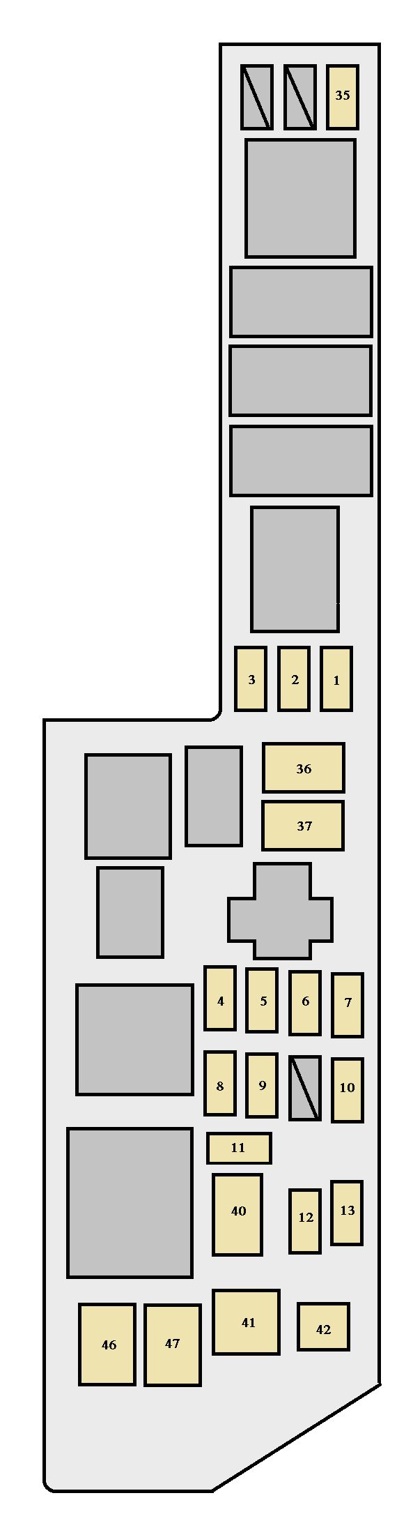
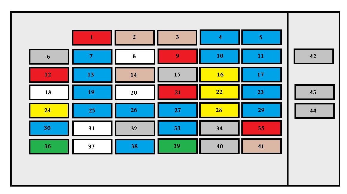
| Fuse |
Ampere rating [A] |
Circuit |
| 1 |
SEAT HTR |
20 |
Seat heaters |
| 2 |
A/F HTR |
25 |
Air fuel ratio sensor |
| 3 |
SPARE |
10 |
Spare fuse |
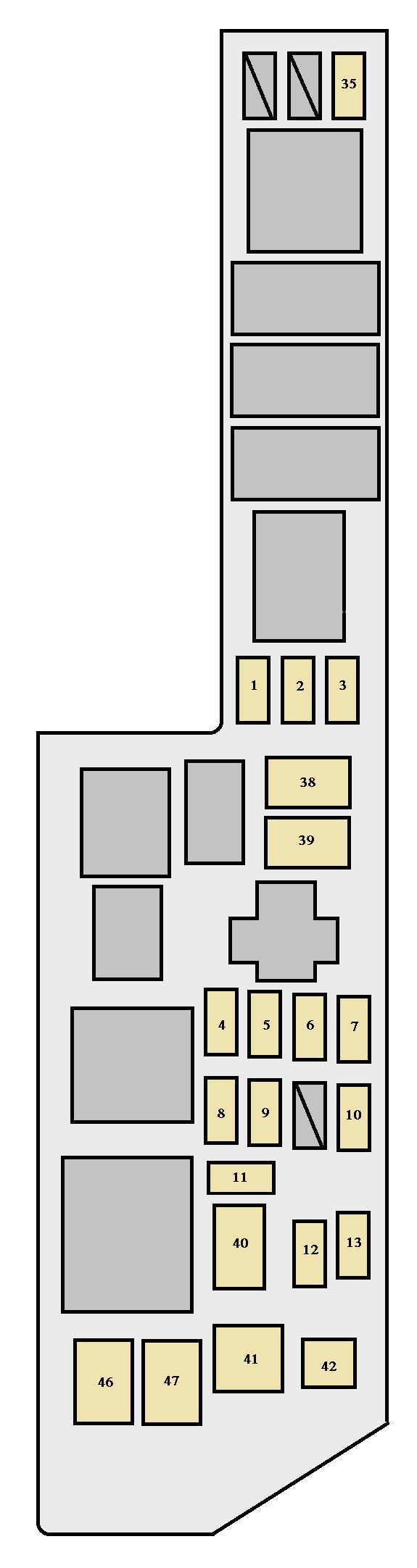
| 4 |
SPARE |
15 |
Spare fuse |
| 5 |
SPARE |
30 |
Spare fuse |
| 6 |
ALT−S |
5 |
Charging system |
| 7 |
HEAD (RH) |
15 |
Right−hand headlight (high beam) |
| 8 |
EFI |
15 |
Multiport fuel injection system/sequential multiport fuel injection system |
| 9 |
HORN |
10 |
Horn, theft deterrent system |
| 10 |
HAZARD |
10 |
Emergency flashers |
| 11 |
AM2 |
30 |
”IGN” and ”STARTER” fuses |
| 12 |
HEAD (LH) |
15 |
15 A: Left−hand headlight (high beam) |
| 13 |
RADIO NO.1 |
20 |
Car audio system |
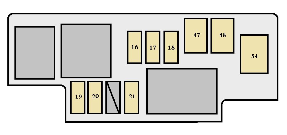
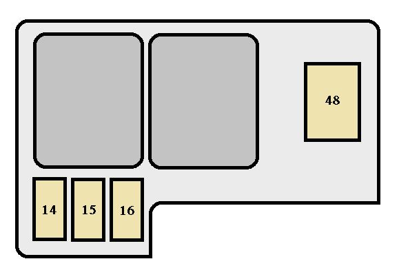
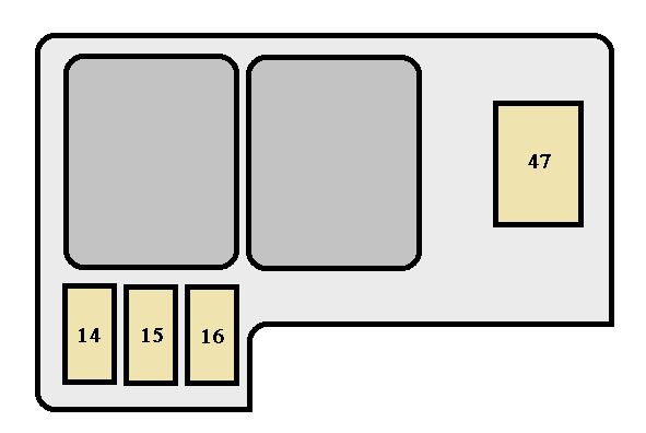
| 14 |
DOME |
10 |
Clock, personal lights, vanity mirror lights, door courtesy lights, luggage compartment light, open door warning light, ignition switch light, theft deterrent system, daytime running light system, interior lights, air conditioning system, wireless remote control, garage door opener |
| 13 |
ECU−B |
10 |
Cruise control system, SRS airbag warning light, power sliding door |
| 14 |
DRL |
5 |
Daytime running light system |
| 15 |
ECU−B |
10 |
Cruise control system, SRS warning light, power sliding door |
| 16 |
FOG |
20 |
Front fog lights |
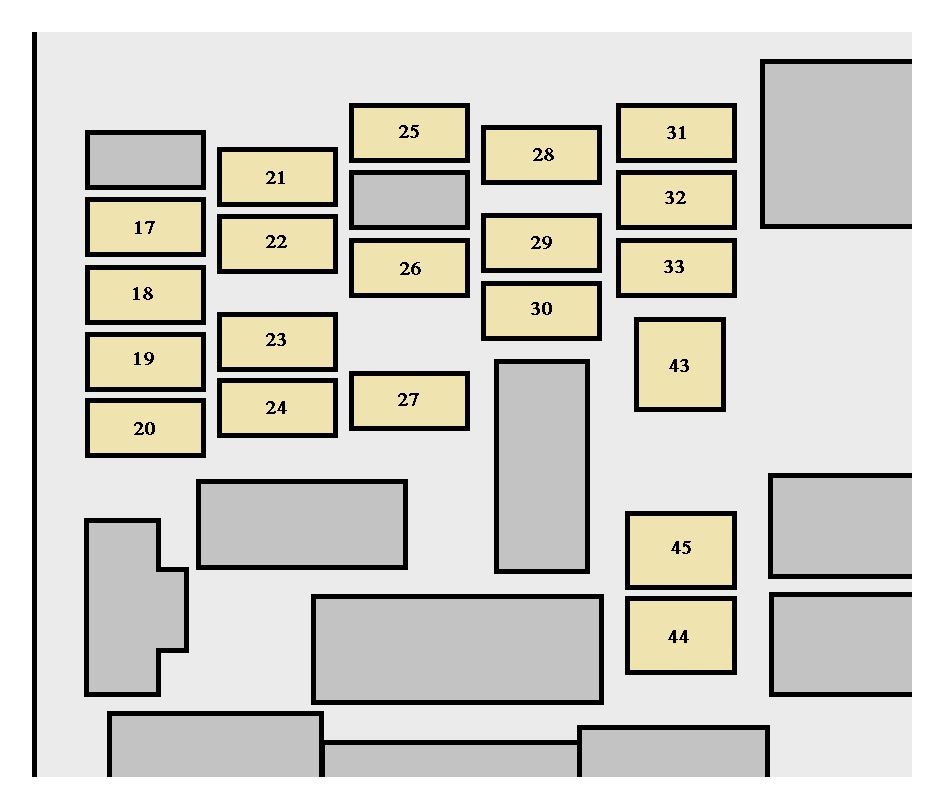
| 17 |
ABS NO.3 |
25 |
Vehicle skid control system |
| 18 |
ABS NO.2 |
25 |
Vehicle skid control system |
| 19 |
H−LP LH (LO) |
10 |
Left−hand headlight (low beam) |
| 20 |
H−LP RH (LO) |
10 |
Right−hand headlight (low beam) |
| 21 |
ABS NO.4 |
5 |
Vehicle skid control system |
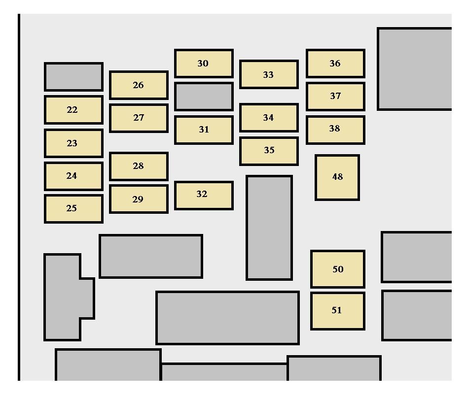
| 22 |
HEATER |
10 |
Air conditioning system, rear window defogger |
| 23 |
GAUGE |
10 |
Gauges and meters, service reminder indicators and warning buzzers (except discharge and open door warning light), power windows, daytime running light system, back−up lights, power sliding door, auto anti−glare inside rear view mirror, compass |
| 24 |
WIPER |
25 |
Windshield wipers and washer, rear window wiper and washer |
| 25 |
MIRROR−HEATER |
10 |
Multiport fuel injection system/sequential multiport fuel injection system, outside rear view mirror defogger |
| 26 |
ECU−IG |
15 |
Cruise control system, anti−lock brake system, locking with wireless remote control system, theft deterrent system |
| 27 |
IGN |
5 |
Gauges and meters, charging system, SRS airbag system, seat belt pretensioners, multiport fuel injection system/sequential multiport fuel injection system |
| 28 |
STOP |
15 |
Stop lights, cruise control system, high−mounted stoplight, tail lights |
| 29 |
TAIL |
10 |
Parking lights, front side marker lights, license plate lights, tail lights |
| 30 |
PWR−VENT |
15 |
Power rear quarter windows |
| 31 |
OBD |
7,5 |
On−board diagnosis system |
| 32 |
PWR−OUTLET |
15 |
Power outlet |
| 33 |
STARTER |
5 |
Multiport fuel injection system/sequential multiport fuel injection system |
| 34 |
DOOR |
20 |
Power door lock system, theft deterrent system |
| 35 |
PANEL |
7,5 |
Gauge and meter, car audio system, clock, air conditioning system, instrument panel light control, rear window defogger, electronically controlled automatic transmission system, emergency flashers, parking lights, seat heaters, power rear quarter windows, power sliding door |
| 36 |
TURN |
7,5 |
Turn signal lights, emergency flashers |
| 37 |
RADIO NO.2 |
7,5 |
Car audio system |
| 38 |
CIG |
15 |
Cigarette lighter, clock, power rear view mirror controls, SRS airbag system, seat belt pretensioners, back−up lights, theft deterrent system, air conditioning system |
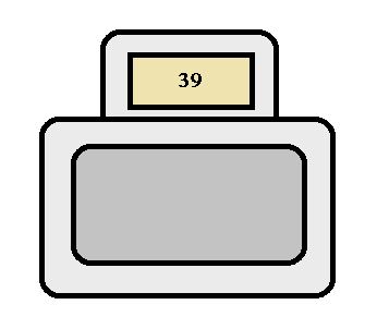
| 39 |
A/C |
5 |
Front air conditioning system |