Ford Ranger (2003) – fuse box diagram
Year of production: 2003
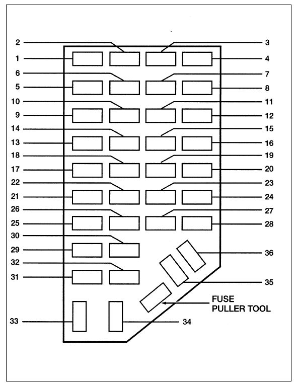
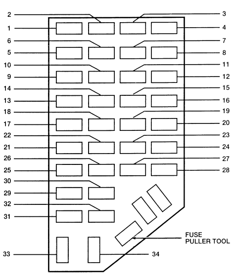
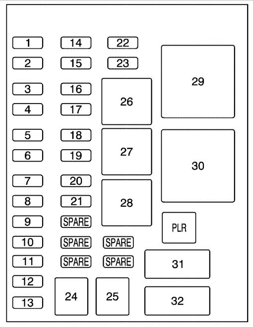
Fuse box in passenger compartment
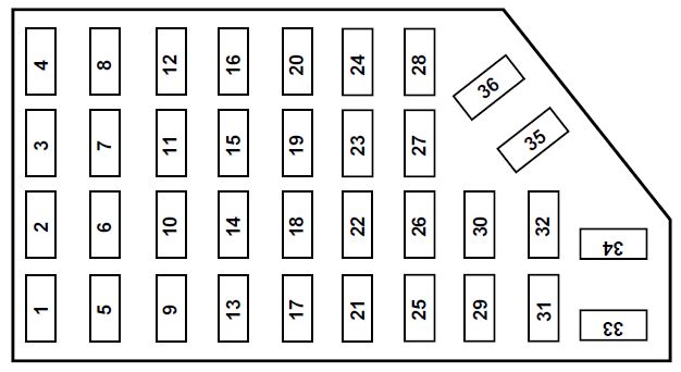
| Fuse/CB | Ampere rating [A] | Description |
| 1 | 5 | Power Mirror Switch |
| 2 | 10 | Daytime Running Lights (DRL), Back-up Lamps, Transmission, Passenger Air Bag Deactivation Switch, Blower Motor Relay |
| 3 | 7,5 | Right Stop/Turn Trailer Tow Connector |
| 4 | – | Not Used |
| 5 | 15 | 4×4 Control Module |
| 6 | 2 | Brake pressure switch |
| 7 | 7,5 | Left Stop/Turn Trailer Tow Connector |
| 8 | — | Not Used |
| 9 | 7,5 | Brake Pedal Position Switch |
| 10 | 7,5 | Speed control servo/amplifier assembly, Generic Electronic Module (GEM), Shift lock actuator, Turn signals, 4×4 |
| 11 | 7,5 | Instrument cluster, 4×4, Main light switch, Truck Central Security Module (TCSM), GEM |
| 12 | — | Not Used |
| 13 | 20 | Brake Pedal Position Switch |
| 14 | 10 | ABS control module |
| 15 | — | Not Used |
| 16 | 30 | Windshield Wiper Motor, Wiper Hi-Lo Relay, Wiper Run/Park Relay |
| 17 | 20 | Cigar Lighter, Data Link Connector (DLC) |
| 18 | — | Not Used |
| 19 | 25 | Powertrain Control Module (PCM) power diode, Ignition, PATS |
| 20 | 7,5 | GEM, Radio |
| 21 | 15 | Hazard flasher |
| 22 | 20 | Auxiliary Power Socket |
| 23 | — | Not Used |
| 24 | 7,5 | Clutch Pedal Position (CPP) switch, Starter Interrupt Relay |
| 25 | — | Not used |
| 26 | 10 | Battery saver relay, Auxiliary relay box, Restraint Central Module (RCM), Generic Electronic Module (GEM), Instrument cluster |
| 27 | — | Not used |
| 28 | 7,5 | GEM, Radio |
| 29 | 20 | Radio |
| 30 | — | Not Used |
| 31 | — | Not Used |
| 32 | — | Not Used |
| 33 | 15 | Headlamps, Daytime Running Lamps (DRL) Module, Instrument Cluster |
| 34 | — | Not Used |
| 35 | 15 | Horn relay (if not equipped with a truck CSM) |
| — | Not Used | |
| 36 | — | Not Used |
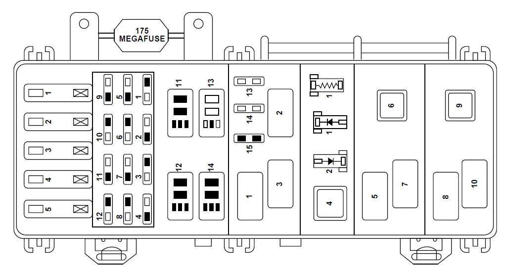
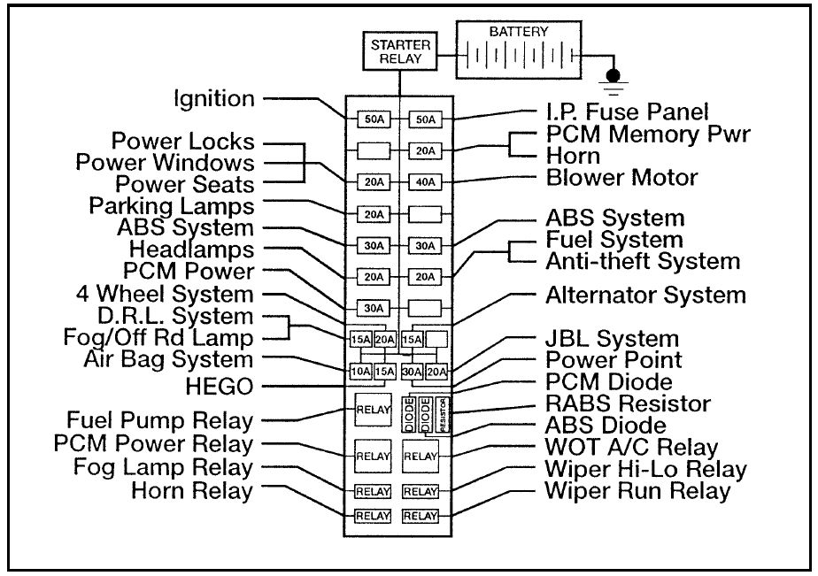
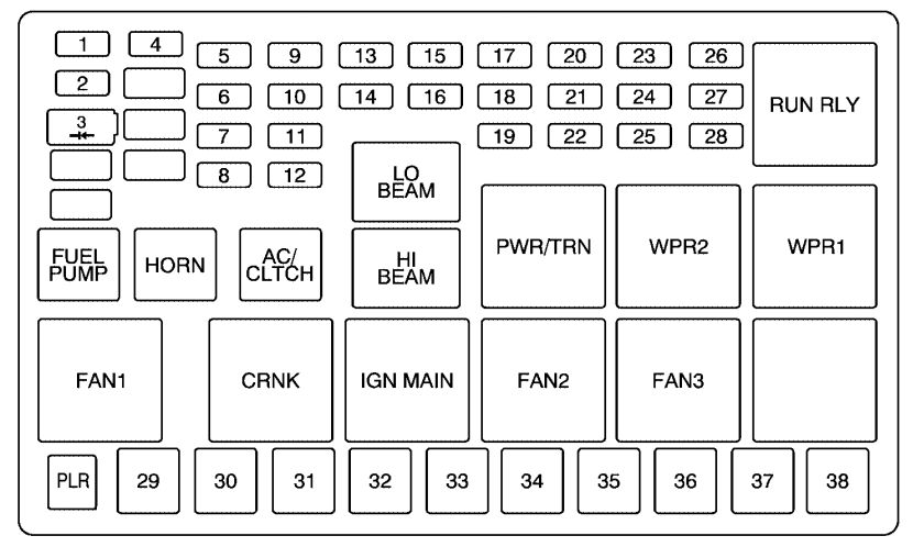
Power distribution box
The power distribution box is located in the engine compartment near the battery.
2.3L engine (if equipped)
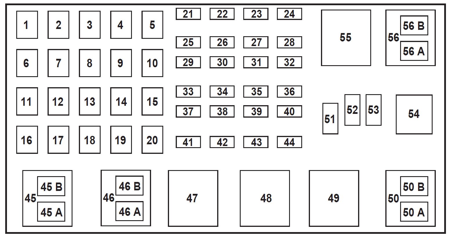
| Fuse/Relay location | Ampere rating [A] | Description |
| 1 | 50** | I/P Fuse Panel |
| 2 | — | Not Used |
| 3 | — | Not Used |
| 4 | — | Not Used |
| 5 | — | Not Used |
| 6 | 50** | ABS Pump Motor |
| 7 | 30* | Powertrain Control Module (PCM) |
| 8 | 20* | Power Door Locks and Remote Entry |
| 9 | — | Not Used |
| 10 | — | Not Used |
| 11 | 50** | Starter Relay, Ignition Switch |
| 12 | 20* | Power Windows |
| 13 | — | Not Used |
| 14 | — | Not Used |
| 15 | — | Not Used |
| 16 | 40** | Blower Motor |
| 17 | 20** | Auxiliary Cooling Fan |
| 18 | — | Not Used |
| 19 | — | Not Used |
| 20 | — | Not Used |
| 21 | 10* | PCM Memory |
| 22 | — | Not Used |
| 23 | 20* | Fuel Pump Motor |
| 24 | 30* | Headlamps |
| 25 | 10* | A/C Clutch Solenoid |
| 26 | — | Not Used |
| 27 | — | Not Used |
| 28 | 30* | ABS module |
| 29 | — | Not Used |
| 30 | 15* | Trailer Tow |
| 31 | 20* | Foglamps, DRL |
| 32 | — | Not Used |
| 33 | 15* | Park Lamp |
| 34 | — | Not Used |
| 35 | — | Not Used |
| 36 | — | Not Used |
| 37 | — | Not Used |
| 38 | 10* | Left Headlamp Low Beam |
| 39 | — | Not Used |
| 40 | — | Not Used |
| 41 | 20* | Heated Oxygen Sensors |
| 42 | 10* | Right Headlamp Low Beam |
| 43 | — | (Resistor) |
| 44 | — | Not Used |
| 45A | — | Wiper HI/LO |
| 45B | — | Wiper Park/Run |
| 46A | — | Fuel Pump |
| 46B | — | Trailer Tow |
| 47 | — | Starter |
| 48 | — | Auxiliary Cooling Fan |
| 49 | — | Not Used |
| 50 | — | Not Used |
| 51 | — | Not Used |
| 52 | — | Not Used |
| 53 | — | PCM Diode |
| 54 | — | PCM |
| 55 | — | Blower |
| 56A | — | A/C Clutch Solenoid |
| 56B | — | Front Washer Pump |
| * Mini Fuses ** Maxi Fuses | ||
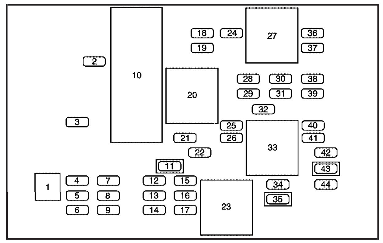
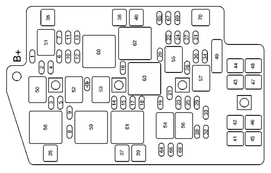
3.0L and 4.0L engines (if equipped)
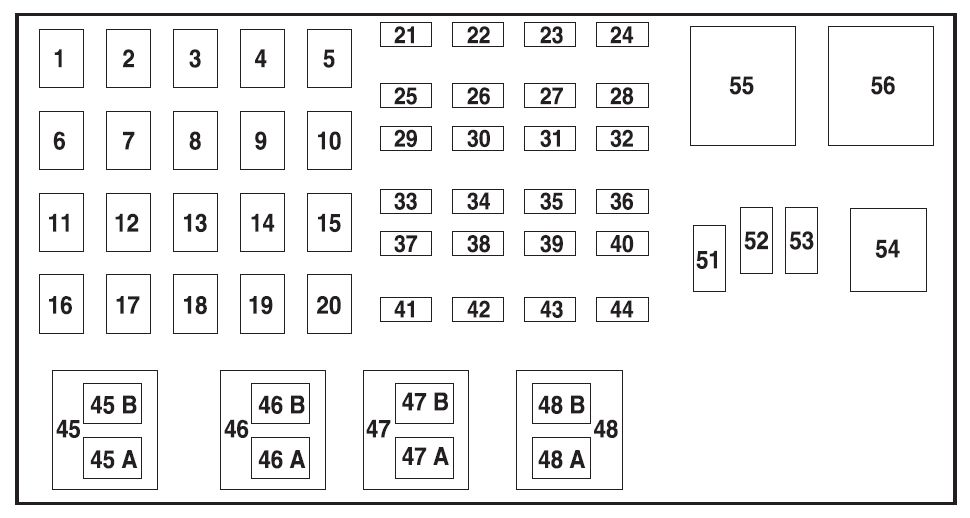
| Fuse/Relay location | Ampere rating [A] | Description |
| 1 | 50** | I/P Fuse Panel |
| 2 | 50** | Amplifier |
| 3 | — | Not Used |
| 4 | — | Not Used |
| 5 | — | Not Used |
| 6 | 50** | ABS Pump Motor |
| 7 | 30* | Powertrain Control Module (PCM) |
| 8 | 20* | Power Door Locks and Remote Entry |
| 9 | — | Not Used |
| 10 | — | Not Used |
| 11 | 50** | Starter Relay, Ignition Switch |
| 12 | 20* | Power Windows |
| 13 | 20* | 4×4 Motor |
| 14 | — | Not Used |
| 15 | — | Not Used |
| 16 | 40** | Blower Motor |
| 17 | — | Not Used |
| 18 | — | Not Used |
| 19 | — | Not Used |
| 20 | — | Not Used |
| 21 | 10* | PCM Memory |
| 22 | — | Not Used |
| 23 | 20* | Fuel Pump Motor |
| 24 | 30* | Headlamps |
| 25 | 10* | A/C Clutch Solenoid |
| 26 | — | Not Used |
| 27 | — | Not Used |
| 28 | 30* | ABS Module |
| 29 | — | Not Used |
| 30 | 15* | Trailer Tow |
| 31 | 20* | Foglamps, Daytime Running Lamps (DRL) |
| 32 | — | Not Used |
| 33 | 15* | Park Lamp |
| 34 | — | Not Used |
| 35 | — | Not Used |
| 36 | — | Not Used |
| 37 | — | Not Used |
| 38 | 10* | Left Headlamp Low Beam |
| 39 | — | Not Used |
| 40 | — | Not Used |
| 41 | 20* | Heated Oxygen Sensors |
| 42 | 10* | Right Headlamp Low Beam |
| 43 | — | Not Used |
| 44 | — | Not Used |
| 45A | — | Wiper High/Low |
| 45B | — | Wiper Park/Run |
| 46A | — | Fuel pump |
| 46B | — | Trailer tow |
| 47A | — | A/C clutch solenoid |
| 47B | — | Front washer pump |
| 48A | — | Fog Lamps |
| 48B | — | Fog Lamp Relay |
| 51 | — | Not Used |
| 52 | — | Not Used |
| 53 | — | PCM Diode |
| 54 | — | PCM |
| 55 | — | Blower |
| 56A | — | Starter |
| * Mini Fuses ** Maxi Fuses | ||
WARNING: Terminal and harness assignments for individual connectors will vary depending on vehicle equipment level, model, and market.