Skoda Fabia (1997 – 2007) – fuse box diagram
Year of production: 1997, 1998, 1999, 2000, 2001, 2002, 2003, 2004, 2005
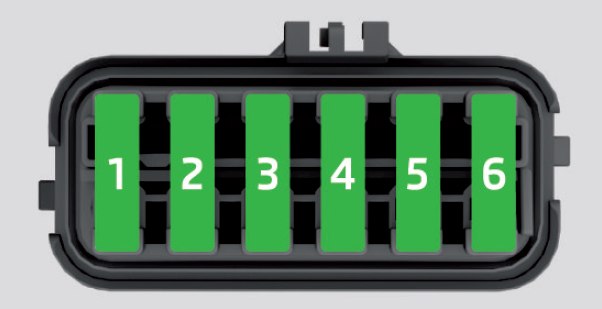
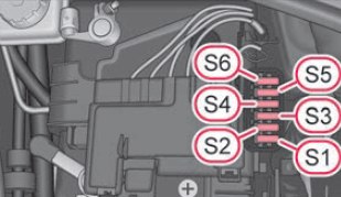
Fuse box in engine compartment
| Number | Power consumer | Ampere rating [A] |
| 1 | Dynamo | 175 |
| 2 | Interior | 110 |
| 3 | Power steering | 50 |
| 4 | Glow plugs | 40 |
| 5 | The radiator fan | 40 |
| 6 | ABS or TCS or ESP | 40 |
| 7 | ABS or TCS or ESP | 25 |
| 8 | The radiator fan | 30 |
| 9 | Not assigned | |
| 10 | Central control unit | 5 |
| 11 | The air conditioning system | 5 |
| 12 | Not assigned | |
| 13 | Automatic gearbox | 5 |
| 14 | Not assigned | |
| 15 | Not assigned | |
| 16 | Not assigned |
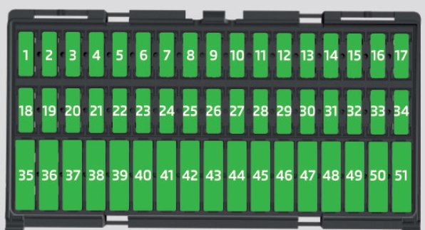
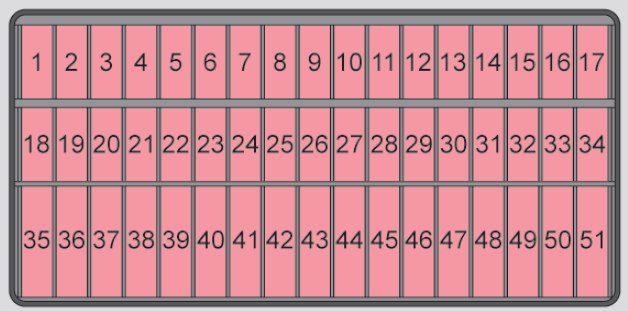
Fuse box in the dash panel
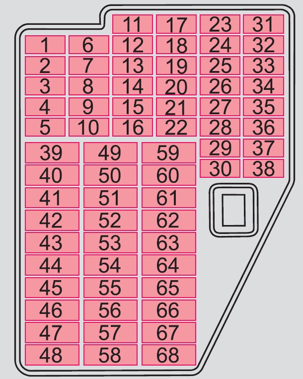
| № |
Power consumer |
A |
| 1 | Instrument cluster, ESP | 5 |
| 2 | Brake lights | 10 |
| 3 | Power supply for the diagnostics, air-conditioning system | 5 |
| 4 | Interior lighting | 10 |
| 5 | Not assigned | – |
| 6 | Lights and Visibility | 5 |
| 7 | Engine electronics, power-assisted steering | 5 |
| 8 | Not assigned | – |
| 9 | Lambda probe | 10 |
| 10 | S-contacta) | 5 |
| 11 | Electrically adjustable rear mirrorb) | 5 |
| 12 | Ventilation system, air-conditioning system, Xenon headlight | 5 |
| 13 | Reversing light | 10 |
| 14 | Diesel engine control unit | 10 |
| 15 | Headlight cleaning system, window wiper | 10 |
| 16 | Instrument cluster | 5 |
| 17 | Petrol engine – control unitc) | 5 |
| 18 | Phone | 5 |
| 19 | Automatic gearbox | 10 |
| 20 | Control unit for lamp failure | 5 |
| 21 | Heated windscreen washer nozzles | 5 |
| 22 | Not assigned | – |
| 23 | Right main beam | 10 |
| 24 | Engine electronics | 10 |
| 25 | Control unit for ABS, TCS control unit for ESP | 5 10 |
| 26 | Not assigned | – |
| 27 | Not assigned | – |
| 28 | Cruise control, switch for the brake and clutch pedal | 5 |
| 29 | Not assigned | – |
| 30 | Main beam on the left and indicator light | 10 |
| 31 | Central locking system – door lock for the boot lid | 10 |
| 32 | Rear window wiper | 10 |
| 33 | Parking light on the right | 5 |
| 34 | Parking light on the left | 5 |
| 35 | Injector – petrol engine | 10 |
| 36 | Licence plate light | 5 |
| 37 | Rear fog light and indicator light | 5 |
| 38 | Heating of the external mirror | 5 |
| 39 | Rear window heater | 20 |
| 40 | Horn | 20 |
| 41 | Front window wiper | 20 |
| 42 | Cigarette lighter, power socket | 15 |
| 43 | Central control unit, selector lever lock for the automatic gearbox | 20 |
| 44 | Turn signals | 15 |
| 45 | Radio, navigation system | 20 |
| 46 | Electrical power window (at the front on the right) | 25 |
| 47 | Not assigned | – |
| 48 | Diesel engine – control unit, injector | 30 |
| 49 | Central locking system | 15 |
| 50 | Low beam on the right | 15 |
| 51 | Power socket in the luggage compartment | 15 |
| 52 | Ignition | 15 |
| 53 | Electrical power window (at the rear on the right) | 25 |
| 54 | Low beam on the left | 15 |
| 56 | Control unit – petrol engine | 20 |
| 57 | Towing device | 25 |
| 58 | Electrical power window (at the front on the left) | 25 |
| 59 | Not assigned | – |
| 60 | Horn for the anti-theft alarm system | 15 |
| 61 | Fuel pump – petrol engine | 15 |
| 62 | Electric sliding/tilting roof | 25 |
| 63 | Seat heaters | 15 |
| 64 | Headlight cleaning system | 20 |
| 65 | Fog lights | 15 |
| 66 | Electrical power window (at the rear on the left) | 25 |
| 67 | Not assigned | – |
| 68 | Fresh air blower | 25 |
| a) For power consumers, e.g. the radio, which can be operated with the ignition switched off as long as the ignition key is not withdrawn. b) For vehicles with an electrical power window system c) It is 15 amps for a vehicle with a 1.2 litre engine. |
||
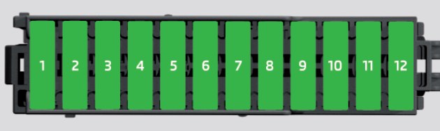
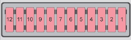
Fuse assignment at battery
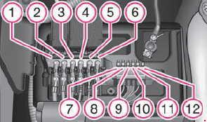
| № |
Power consumer |
A |
| 1 | Dynamo | 175 |
| 2 | Interior | 110 |
| 3 | The radiator fan | 40 |
| 4 | ABS or TCS or ESP | 40 |
| 5 | Power steering | 50 |
| 6 | Glow plugsa) | 50 |
| 7 | ABS or TCS or ESP | 25 |
| 8 | The radiator fan | 30 |
| 9 | The air conditioning system | 5 |
| 10 | Engine control unit | 15 |
| 11 | Central control unit | 5 |
| 12 | Automatic gearbox | 5 |
| a) Only for diesel engine 1.9/96 kW. | ||
WARNING: Terminal and harness assignments for individual connectors will vary depending on vehicle equipment level, model, and market.