Kia Sephia (2000 – 2001) – fuse box diagram
Year of production: 2000, 2001
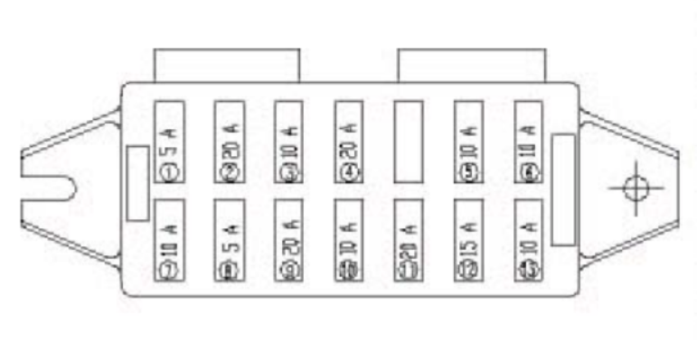
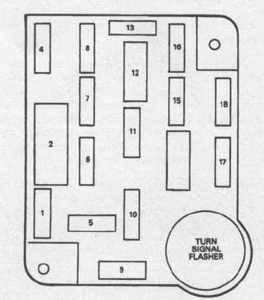
Driver’s side kick panel
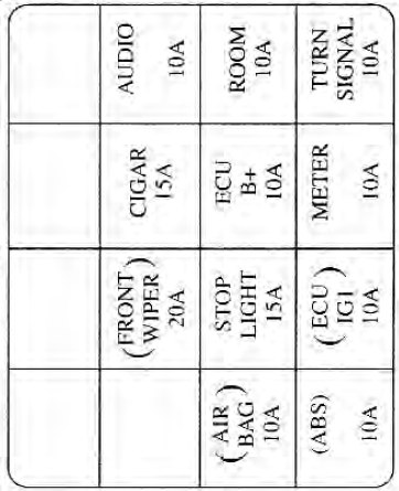
| Description | Ampere rating [A] | Protected component |
| FRONT WIPER | 20 | Front wiper system |
| CIGAR | 15 | Cigarette lighter |
| AUDIO | 10 | Audio, remote control mirror |
| AIR BAG | 10 | Air bag diagnostic unit |
| STOP LIGHT | 15 | Rear brake light, high-mounted stoplight |
| ECU B+ | 10 | Shift lock actuator, transaxle control module, radio, engine control module |
| ROOM | 10 | Interior light, clock, ignition key reminder switch, rear cargo area light |
| ABS | 10 | ABS control unit |
| ECU IG1 | 10 | Transaxle control module, shift lock actuator, ABS control unit, DRL unit |
| METER | 10 | Instrument panel, back-up switch, electronic time control module, inhibit switch |
| TURN SIGNAL | 10 | Hazard switch, front and rear turn lights, turn indicator |
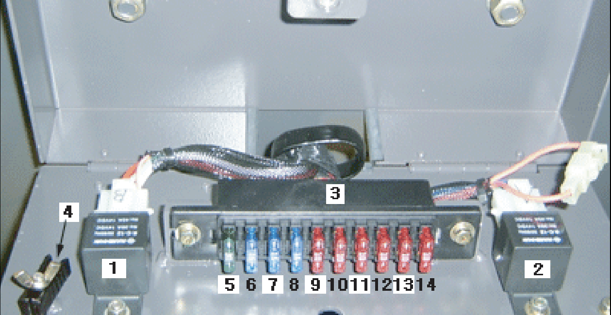
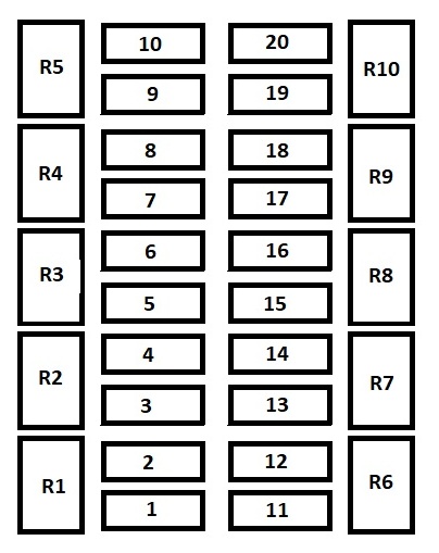
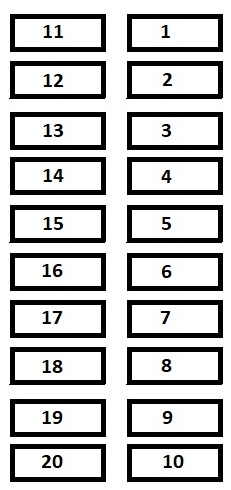
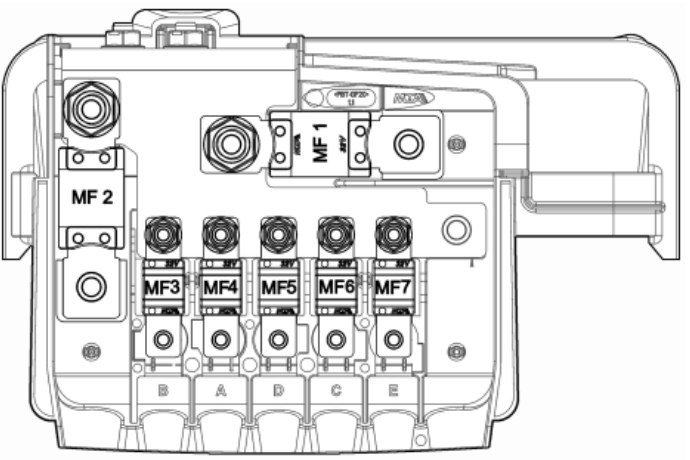
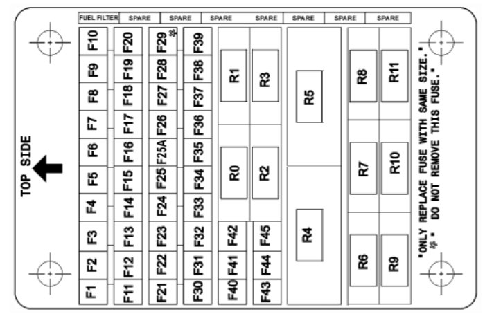
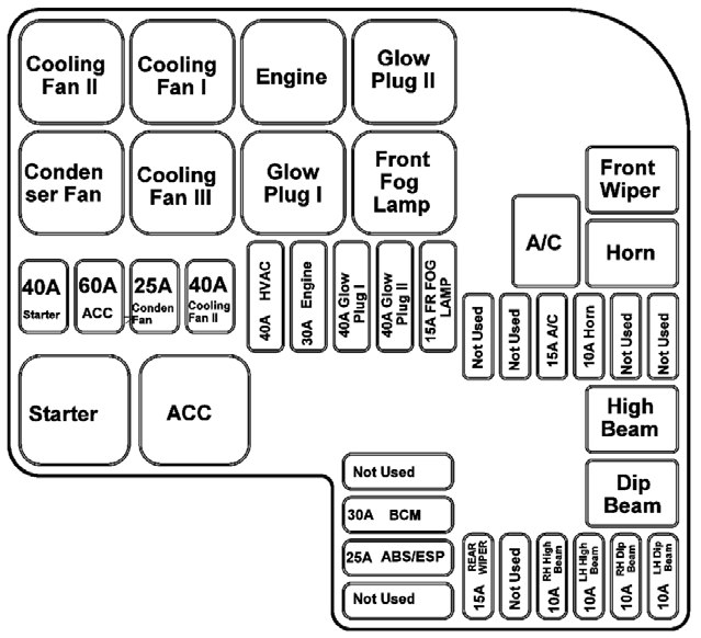
Engine compartment (fuses)
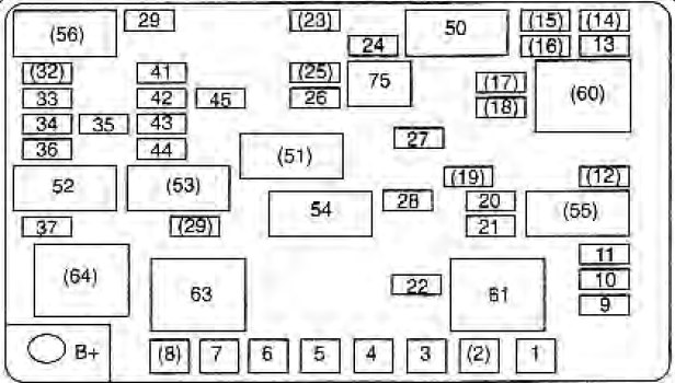
| Number | Description | Ampere rating [A] | Protected component |
| 1 | IGN1 | 20 | Ignition switch |
| 2 | ABS | 30 | ABS pump motor |
| 3 | TNS | 30 | Tail light, license plate light |
| 4 | FUTURE | 20 | Not applicable |
| 5 | 2ND AIR | 30 | Not applicable |
| 6 | FUTURE | 30 | Not applicable |
| 7 | COOL/FAN | 30 | Cooling fan |
| 8 | COND/FAN | 20 | A/C condenser fan |
| 9 | STARTER | 15 | Start signal, fuel pump |
| 10 | BLOWER | 25 | Blower motor |
| 11 | SR/ACC | 10 | Ignition switch |
| 12 | RR FOG | 10 | Not applicable |
| 13 | HAZARD | 15 | Hazard and turn signal light |
| 14 | D/LOCK | 25 | Door locks |
| 15 | ABS | 30 | Anti-lock brake system control |
| 16 | SUNROOF | 15 | Not applicable |
| 17 | P/W RH | 20 | Power window motor |
| 18 | P/W LH | 20 | Power window motor |
| 19 | RR WIPER | 15 | |
| 20 | IGN2 | 25 | Ignition switch |
| 21 | HEAD | 25 | Headlights |
| IG 2 | 30 | Ignition switch | |
| 22 | IG COIL | 15 | Ignition coil, condenser, generator IC regulator, diagnostic connector |
| 23 | OBD-II | 10 | OBD-II |
| 24 | DEFOG | 20 | Rear window defroster |
| 25 | O2 DOWN | 20 | Rear O2 sensor |
| 26 | O2 UP | 10 | Front O2 sensor |
| 27 | FUEL PUMP | 10 | Fuel pump unit |
| 28 | INJECTOR | 10 | Fuel injectors, camshaft position sensor, purge solenoid valve, EVAP canister close valve, IAC actuator, mass air flow sensor, EGR stepper motor, fuel pump relay coil, vehicle speed sensor |
| 29 | A/CON | 10 | A/C compressor controls, cooling fan |
| 30 | BTN | 30 | Brake light, high-mounted stoplight |
| 31 | |||
| 32 | FRT FOG | 15 | |
| 33 | TAIL LH | 10 | License plate light, tail lights, rear combination light, instrument panel illumination |
| 34 | TAIL RH | 10 | |
| 35 | HEAD LOW | 15 | Headlight |
| 36 | HEAD HI | 15 | Headlight |
| 37 | HORN | 15 | Horn |
| 41 | SPARES | 10 | Spare |
| 42 | SPARES | 15 | Spare |
| 43 | SPARES | 20 | Spare |
| 44 | SPARES | 25 | Spare |
| 45 | SPARES | 30 | Spare |
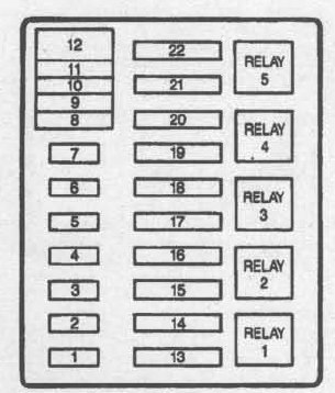
Relays
| Number | Description |
| 50 | Defog |
| 51 | Fuel pump |
| 52 | Horn |
| 53 | Air cond |
| 54 | EGI mainamp |
| 55 | Headlamp |
| 56 | TNS |
| 60 | P/Windows |
| 61 | Blower |
| 63 | Cooling fan |
| 64 | Condenser fan |
| Number | Description |
| 75 | Fuse puller |
WARNING: Terminal and harness assignments for individual connectors will vary depending on vehicle equipment level, model, and market.