Seat Exeo ST (2009) – fuse box diagram
Year of production: 2009
Fuse box
The fuses are located on the left side of dash panel.
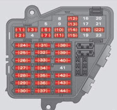
| Number | Component | Ampers |
| 1 | Climate control | 10 |
| 2 | Footwell lamps | 5 |
| 3 | Heated washer jets | 5 |
| 4 | Radiator fan | 5 |
| 5 | Telephone, multifunction switch, rear window sun blind | 10 |
| 6 | Air conditioner (air purity sensor), pressure sensor | 5 |
| 7 | Electronic Stabilisation Program (ESP), brake light switch, clutch pedal switch, steering angle sensor | 10 |
| 8 | Telephone | 5 |
| 9 | Brake servo (vacuum pump) | 15 |
| 10 | Self-directing headlights (adaptive light) right | 5 |
| 11 | Tyre pressure monitoring | |
| 12 | Diagnostic socket | 10 |
| 13 | Steering column unit | 10 |
| 14 | Brake lights | 10 |
| 15 | Instrument panel | 10 |
| 16 | Vacant | 5 |
| 17 | Parking aid, self-levelling suspension, tyre pressure monitoring system, rain/ light sensor | 10 |
| 18 | Self-directing headlights (adaptive light) left | 5 |
| 19 | Fog lights | 15 |
| 20 | Vacant | |
| 21 | Vacant | |
| 22 | Driver’s door / front passenger’s door | 15 |
| 23 | Rear doors | 15 |
| 24 | Central electrics unit for convenience equipment | 20 |
| 25 | Heater blower | 30 |
| 26 | Rear window heater | 30 |
| 27 | Electrical socket for trailer (control unit) | 30 |
| 28 | Fuel pump, auxiliary pump for diesel | 20 |
| 29 | Vacant | |
| 30 | Sliding/tilting sunroof | 20 |
| 31 | Diagnosis connection, automatic anti-dazzle interior mirror with automatic adjustment | 15 |
| 32 | Towing socket | 15 |
| 33 | Lighter | 20 |
| 34 | Vacant | |
| 35 | Luggage compartment power point* | 20 |
| 36 | Wiper system | 30 |
| 37 | Pump for windscreen washer and headlight washer system | 30 |
| 38 | Central electrics unit for convenience equipment, bonnet unlocking | 15 |
| 39 | Radio | 20 |
| 40 | Horn | 25 |
| 41 | Vacant | 30 |
| 42 | Electronic stabilisation programme (ESP) | 25 |
| 43 | Engine management | 15 |
| 44 | Seat heating | 35 |
WARNING: Terminal and harness assignments for individual connectors will vary depending on vehicle equipment level, model, and market.