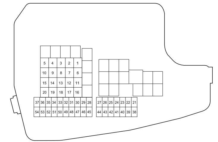
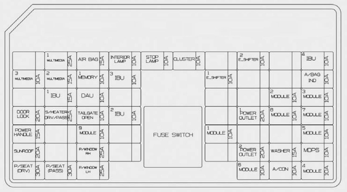
Ariel Atom 2 (2006) – fuse box diagram

Ariel Atom 2 (2006) – fuse box diagram

Year of production: 2006

GM FUSE PANELS (Without Master Battery Switch)

Fuse box 1

Relays Fuse Ampere rating [A] Description
R1 After Cool F1 30 Battery
F2 15 Brake Light
R2 Power Train F3 15 Light Switch
F4 20 Power Point
R3 F5 10 ALDL
F6 10 ECM Battery
R4 F7 10 Hazard
F8 15 Horn
R5 F9
F10

Fuse box 2

Relays Fuse Ampere rating [A] Description
R1 Starter F1 20 Ignition
F2 15 Fuel Pump
R2 Cooling Fan F3 20 High Beam
F4 20 Low Beam
R3 High Beam F5 No Fuse
F6 15 Power Train
R4 Low Beam F7 15 BU Lamp Switch & Master Lube
F8 2 Dash
R5 Fuel Pump F9 15 Run Lights
F10  15 Turn Signal

GM FUSE PANELS (With Master Battery Switch)

Fuse box 1

Relays Fuse Ampere rating [A] Description
R1 After Cool F1 30 Battery
F2 15 Brake Light
R2 Power Train F3 15 Light Switch
F4 20 Power Point
R3 F5 10 ALDL
F6 No Fuse
R4 F7 10 Hazard
F8 15 Horn
R5 F9
F10

Fuse box 2

Relays Fuse Ampere rating [A] Description
R1 Starter F1 20 Ignition
F2 15 Fuel Pump
R2 Cooling Fan F3 20 High Beam
F4 20 Low Beam
R3 High Beam F5 10 ECU Battery
F6 15 Power Train
R4 Low Beam F7 15 BU Lamp Switch & Master Lube
F8 20 Dash
R5 Fuel Pump F9 15 Run Lights
F10 15 Turn Signal

HONDA FUSE PANELS

Fuse box 1

Relays Fuse Ampere rating [A] Description
R1 After Cool F1 30 Battery
F2 15 Brake Light
R2 Power Train F3 15 Light Switch
F4 20 Power Point
R3 Cooling Fan F5 10 ALDL
F6 10 ECM Battery+
R4 Main Relay F7 10 Hazard
F8 15 Horn
R5 F9
F10

Fuse box 2

Relays Fuse Ampere rating [A] Description
R1 Starter F1 20 Ignition
F2 15 Fuel Pump
R2 Cooling Fan F3 20 High Beam
F4 20 Low Beam
R3 High Beam F5 No Fuse ECM
F6 15 Power Train
R4 Low Beam F7 15 BU Lamp Switch
F8 20 Dash
R5 Fuel Pump F9 15 Running Lights
F10 15 Turn Signal


WARNING: Terminal and harness assignments for individual connectors will vary depending on vehicle equipment level, model, and market.

Toyota 86 (2017 – 2018) – fuse box diagram

Toyota 86 (2017 – 2018) – fuse box diagram

Year of production: 2017, 2018

Engine compartment

Toyota 86 - fuse box diagram - engine compartment
Toyota 86 – fuse box diagram – engine compartment
Description Ampere rating [A] Description
1 MIR HTR 7,5 Outside rear view mirror defoggers
2 RD 25 Electric cooling fan
3 (PUSH-AT) 7,5 Engine control unit
4 ABS NO. 1 40 ABS
5 HEATER 50 Air conditioning system
6 WASHER 10 Windshield washer
7 WIPER 30 Windshield wipers
8 RR DEF 30 Rear window defogger
9 (RR FOG) 10
10 D FR DOOR 25 Power window (driver’s side)
11 (CDS) 25 Electric cooling fan
12 D-OP 25
13 ABS NO. 2 25 ABS
14 D FL DOOR 25 Power window (passenger’s side)
15 SPARE Spare fuse
16 SPARE Spare fuse
17 SPARE Spare fuse
18 SPARE Spare fuse
19 SPARE Spare fuse
20 SPARE Spare fuse
21 ST 7,5 Starting system
22 ALT-S 7,5
23 (STR LOCK) 7,5
24 D/L 20 Power door lock
25 ETCS 15 Engine control unit
26 (AT+B) 7,5 Transmission
27 (AM2 NO. 2) 7,5
28 EFI (CTRL) 15 Engine control unit
29 EFI (HTR) 15 Multiport fuel injection system/sequential multiport fuel injection system
30 EFI (IGN) 15 Starting system
31 EFI (+B) 7,5 Engine control unit
32 HAZ 15 Turn signal lights, emergency flashers
33 MPX-B 7,5 Gauge and meters
34 F/PMP 20 Multiport fuel injection system/sequential multiport fuel injection system
35 IG2 MAIN 30 SRS airbag system, engine control unit
36 DCC 30 Interior light, wireless remote control, main body ECU
37 HORN NO. 2 7,5 Horn
38 HORN NO. 1 7,5 Horn
39 H-LP LH LO 15 Left-hand headlight (low beam)
40 H-LP RH LO 15 Right-hand headlight (low beam)
41 H-LP LH HI 10 Left-hand headlight (high beam)
42 H-LP RH HI 10 Right-hand headlight (high beam)
43 INJ 30 Multiport fuel injection system/sequential multiport fuel injection system
44 H-LP WASHER 30
45 AM2 NO. 1 40 Starting system, engine control unit
46 EPS 80 Electric power steering
47 A/B MAIN 15 SRS airbag system
48/ ECU-B 7,5 Wireless remote control, main body ECU
49 DOME 20 Interior light
50 IG2 7,5 Engine control unit

Instrument panel

Toyota 86 - fuse box diagram - instrument panel
Toyota 86 – fuse box diagram – instrument panel
Description Ampere rating [A] Description
1 ECU ACC 10 Main body ECU, outside rear view mirrors
2 P/POINT No.2 15 Power outlet
3 PANEL 10 Illumination
4 TAIL 10 Tail lights
5 DRL 10 Daytime running light system
6 STOP 7,5 Stop lights
7 OBD 7,5 On-board diagnosis system
8 HEATER-S 7,5 Air conditioning system
9 HEATER 10 Air conditioning system
10 FR FOG LH 10
11 FR FOG RH 10
12 BK/UP LP 7,5 Back-up lights
13 ECU IG1 10 ABS, electric power steering
14 AM1 7,5 Starting system
15 AMP 15 Audio system
16 AT UNIT 15 Transmission
17 GAUGE 7,5 Gauge and meters
18 ECU IG2 10 Engine control unit
19 SEAT HTR LH 10
20 SEAT HTR RH 10
21 RADIO 7,5 Audio system
22 P/POINT No.1 15 Power outlet

WARNING: Terminal and harness assignments for individual connectors will vary depending on vehicle equipment level, model, and market.

Mazda MPV (2000 – 2001) – fuse box diagram

Mazda MPV (2000 – 2001) – fuse box diagram

Year of production: 2000, 2001

Fuse block (Engine compartment)

Mazda MPV - fuse box - engine compartment
Mazda MPV – fuse box –
engine compartment
Description Ampere rating [A] Description
1 DEFOG 40 Rear window defroster
2 BTN 40 STOP, HAZARD, ROOM, D.LOCK and DRL fuses
3 COOLING FAN 1 30 Cooling fan
4 HEATER 40 Heater
5 R.HEAT 30 Rear heater*, For protection of varius circuits
6 IG KEY 1 40 METER, ENGINE and WIPER fuse
7 IG KEY2 40 A/C, P.WIND, SUN ROOF and R.WIP fuses
8 (COOLING FAN 2) 30 Cooling fan
9 (A/C) 10 Air conditioner*, For protection of various circuits*
10 TAIL 15 Taillights
11
12 HORN 15 Horn
13 (FOG) 15 For protection of various circuits
14
15 HEAD L 15 Headlight-left
16 HEAD R 15 Headlight-right
17
18
19 ABS 60 Anitlock brake system*, For protection of varius cicuits
20 ENGINE 30 Engine control system
21
22 MAIN 120 For protection of all circuits

Fuse block (Driver’s side)

Mazda MPV - fuse box - driver's side
Mazda MPV – fuse box –
driver’s side
Description Ampere rating [A] Description
1 WIPER 20 Windshield wipers and washer
2 (P.WIND) 30 Power windows*, For protection of various circuits*
3 (SUN ROOF) 15 Sunroof*, For protection of various circuits*
4 R.WIP 10 Rear window wiper and washer
5 (SEAT) 20 For protection of various circuits*
6 (M.DEF) 10 Mirror defroster*, For protection of various circuits*
7 (A/C) 10 Air conditioner*, For protection of various circuits*
8 (DRL) 10 For protection of various circuits*
9
10 (H/CLEAN) 20 For protection of various circuits*
11
12 HAZARD 10 Hazard warning
13 ROOM 15 Interiorr lights, Lifegate light
14 (AUX POWER) 25 Accessory socket
15 (CLOSER LH) 20 For protection of various circuits*
16 (AUDIO) 10 Audio system*, For protection of various circuits*
17 (D.LOCK) 30 Power door locks*, For protection of various circuits*
18
19 ENGINE 10 Engine control system
20 METER 10 Instrument cluster
21 STOP 15 Brake lights
22 (CLOSER RH) 15 For protection of various circuits*
23 (ACC. DELAY) 30 Power windows delay*, For protection of various circuits*
24 METER 15 Instrument cluster, INH switch
25 (ST.SIGN) 10 Starter signal
26 CIGAR 25 Lighter*
27
28

WARNING: Terminal and harness assignments for individual connectors will vary depending on vehicle equipment level, model, and market.

Mazda MX-5 (2018) – fuse box diagram

Mazda MX-5 (2018) – fuse box diagram

Year of production: 2018

Fuse block (Engine compartment)

Mazda MX5 - fuse box diagram - engine compartment
Mazda MX5 – fuse box diagram – engine compartment
Position Description Fuse rating [A] Protected component
1 AUDIO DCDC REG 30 Audio system
2 IG2 30 For protection of various circuits
3 INJECTOR ENG. SUB 30 Engine control system*
4 SCR1 EVVT 20 Engine control system*
5 P.WINDOW1 30 Power windows
6 IG1 2 30 For protection of various circuits
7
8 ADD FAN DE 50 Cooling fan
9 DEFOG 40 Rear window defogger*
10 DCDC DE 40
11 EPB R 20 Electric parking brake (EPB) (RH)
12 EPB L 20 Electric parking brake (EPB) (LH)
13 CABIN.+B 50 For protection of various circuits
14 FAN GE 30 Cooling fan*
15 ENG.MAIN 40 Engine control system
16 ABS/DSC M 50 ABS, Dynamic stability control system
17 HEATER 40 Air conditioner*
18 WIPER 20 Front window wiper and washer
19 FAN DE 50 Cooling fan*
20 ADD FAN GE 30 Cooling fan*
21 ENGINE3 15 Engine control system
22 ENGINE2 15 Engine control system
23 AUDIO2 7,5 Audio system
24 METER2 10
25 SRS1 7,5 Air bag
26 METER1 10 Instrument cluster
27 ENGINE.IG1 7,5 Engine control system
28 AT 15 Transaxle control system*, Ignition switch
29 H/CLEAN 20
30 A/C 7,5 Air conditioner
31 AT PUMP 15
32 HORN 15 Horn
33 R.WIPER 15 Theft-deterrent system
34 H/L HI 20 Headlight high beam
35
36 WIPER.DEI 20 Windshield wiper de-icer
37 ENG.+B 7,5 Engine control system
38 H/L LOW L 15 Headlight low beam (LH)
39 GLOW SIG 5
40 ENGINE1 ENGINE4 15 Engine control system
41 C/U IG1 15 Engine control system
42 ST.HEATER 15 Heated steering wheel
43
44 AUDIO1 25 Audio system
45 ABS/DSC S 30 ABS, Dynamic stability control system
46 FUEL PUMP 15 Fuel system*
47 FUEL WARM 25 Fuel warmer
48 TAIL 15 Taillights, License plate lights
49 SCR2 FUEL PUMP2 25 Fuel system*
50 HAZARD 25 Hazard warning flashers, Turn signal lights/Front side-marker lights, Parking lights
51 H/L LOW R 15 Headlight low beam (RH)
52 OUTLET 25 Accessory sockets
53 STOP 10 Brake lights
54 ROOM 25 Overhead light
* Some models

 Fuse block (Left side)

Mazda MX5 - fuse box diagram - left side
Mazda MX5 – fuse box diagram – left side
Position Description Fuse rating [A] Protected component
1 P.SEAT D 30 Power seat*
2 P.SEAT P1 30 Power seat*
3 R.SEAT W1 20 Seat warmer*
4 P.WINDOW2 25 Power windows
5 SRS2/ESCL 15 Air bag/Electric steering lock
6 D.LOCK 25 Power door locks
7 SEAT WARM 20 Seat warmer*
8 SUNROOF 10 Moonroof*
9 R.OUTLET 15
10 MIRROR 7,5 Power control mirror
11 AT IND 7,5 AT shift indicator
12 INTERIOR1 15 For protection of various circuits
13 INTERIOR2 10 Overhead light
14 R.OUTLET2 15 Accessory sockets
15 USB 7,5 USB power outlet
16 SCR3 15 Engine control system*
17 SCR4 15 Engine control system*
18 AUDIO3 15 Audio system*
19 R.SHADE 7,5
20 M.DEF 7,5 Mirror defogger
21
* Some models

WARNING: Terminal and harness assignments for individual connectors will vary depending on vehicle equipment level, model, and market.

Mazda MX-5 (2001) – fuse box diagram

Mazda MX-5 (2001) – fuse box diagram

Year of production: 2001

Fuse block (Engine compartment)

Mazda MX-5 - fuse box - engine compartment
Mazda MX-5 – fuse box –
engine compartment
Position Description Fuse rating [A] Protected component
1 HEAD 40 Headlights, Rear defroster, Auto antenna*
2 FUEL INJ 30 Fuel injection
3 MAIN 100 For protection of all circuits
4 IG KEY 60 All ignition related circuits
5 BLOWER 30 Blower motor
6 FAN 30 Cooling fan, Additional fan (air conditioner)*
7 BTN 1 30 Taillights, Dashboard illumination*
8 BTN 2 20 Audio amp, Turn signal lights
9 ABS 20 Antilock brake system*
10 STOP 15 Brake lights, Horn, Shift lock
* – some models

Fuse panel (Driver’s side)

Mazda MX-5 - fuse box - driver's side
Mazda MX-5 – fuse box –
driver’s side
Position Description Fuse rating [A] Protected component
1 AD FAN 20 Add fan motor, Magnet clutch
2 HEAD.LH 15 Headlights (LH)
3 HEAD.RH 15 Headlights (RH)
4
5 ST.SIG 7,5 Instrument cluster, Cruise control*
6
7 CIGAR 20 Cigar lighter
8 RADIO 10 Audio
9 F.FOG 15 Fog lights*
10 TAIL 15 Taillights, Front parking lights, Side-marker lights
11 ENGINE 15 Engine control system
12 METER 15 Instrument cluster
13 TURN 7,5 Turn signal lights
14 A/B 10 Supplemental restraint system, Antilock brake system*
15 WIPER 20 Windshield wipers and washer
16 P.WIND 30 Power windows
17 A/C 7,5 Air conditioner
18 HAZARD 10 Turn signal lights
19 D.LOCK 10 Power door lock*
20 AUDIO 20 Audio amp*
21 DEFOG 15 Rear defroster
22 ROOM 10 Interior light, Auto antenna*, Warning buzzers
* – some models

WARNING: Terminal and harness assignments for individual connectors will vary depending on vehicle equipment level, model, and market.

Mazda MX-5 (2000) – fuse box diagram

Mazda MX-5 (2000) – fuse box diagram

Year of production: 2000

Fuse block (Engine compartment)

Mazda MX-5 - fuse box - engine compartment
Mazda MX-5 – fuse box –
engine compartment
Position Description Fuse rating [A] Protected component
1 HEAD 40 Headlights
2 FUEL INJ 30 Fuel injection, Alternator
3 MAIN 100 For protection of all circuits
4 IG KEY 60 All ignition related circuits
5 BLOWER 30 Blower motor
6 FAN 30 Cooling fan, Additional fan (air conditioner)*
7 BTN 1 30 Taillights*, Turn signal lights, Instrument panel illumination8, Auto antenna*
8 BTN 2 20 Rear defroster*, Audio amp*
9 ABS 20 Antilock brake system*
10 STOP 15 Brake lights, Horn, Shift lock

Fuse panel (Driver’s side)

Mazda MX5 - fuse box diagram - driver's side
Mazda MX5 – fuse box diagram – driver’s side
Position Description Fuse rating [A] Protected component
1 ROOM 10 Interior light, Auto antenna, Warning buzzers
2 DEFOG 15 Rear defroster*
3 TAIL 15 Tail lights, Front parking lioghts, Slide marker lights
4 HAZARD 10 Turn signal lights
5 D.LOCK* 10 Power door lock*
6 AUDIO* 20 Audio amp*
7 CIGAR 20 Cigar lighter
8 RADIO 10 Audio
9 WIPER 20 Windshield wipers ans washer
10 A/C 10 Air conditioner*
11 P.WIND 30 Power windows
12 F.FOG* 20 Fog lights
13 ENGINE 15 Engine control system
14 METER 15 Instrument cluster
15 TURN 10 Turn signal lights
16 A/B 10 Suplemental restraint system, Antilovk brake system
17
18 ST.SIG* 10 Instrument cluster, Cruise control*
19 R.FOG* 10
20 HEAD.RH 15 Headlights (RH)
21 HEAD.LH 15 Headlights (LH)
22
* –  some models

WARNING: Terminal and harness assignments for individual connectors will vary depending on vehicle equipment level, model, and market.

Mazda 626 (2000 – 2001) – fuse box diagram

Mazda 626 (2000 – 2001) – fuse box diagram

Year of production: 2000, 2001

Fuse block (Engine compartment)

Mazda 626 - fuse box - engine compartment
Mazda 626 – fuse box –
engine compartment
Position Description Fuse rating [A] Protected component
1 EGI INJ 30 Fuel injection system
2 DEFOG 40 Rear window defroster
3
4 MAIN 100 For protection of all circuits
5 IG KEY 30 RADIO, SUNROOF*, TURN, METER, ENGINE, POWER WINDOW*, WIPER fuses, Ignition system
6 HEATER 40 Heater, Air conditioner*
7 BTN 40 TAIL, STOP, ROOM, DOOR LOCK, HAZARD, POWER SEAT* fuses
8 COOLING FAN 30 Cooling fan
9 AD FAN 30 Additional fan*
10 (ABS) 60 Antilock brake system*
11 TAIL 15 Taillights, Parking lights, Dashboard illumination, License plate lights, Switches illumination
12 HORN 15 Horn
13 (ABS) 20 Antilock brake system*
14
15 ST. SIGN 10 Starter signal
16 H/L-L 15 Headlight (Left)
17 H/L-R 15 Headlight (Right)
18 (ABS) 20 Antilock brake system*
* – some models

Fuse panel (Driver’s side)

Mazda 626 - fuse box - driver's panel
Mazda 626 – fuse box –
driver’s panel
Position Description Fuse rating [A] Protected component
1 AUDIO 15 Audio system*
2 ROOM 15 Interior lights, Trunk light
3 S/ROOF 15 Sunroof*
4 METER 10 Gauges, Reverse lights
5 D.LOCK 30 Power door lock*
6 HAZARD 15 Hazard warning lights
7 A/B&ABS 10 Air bag system, Antilock brake system*
8
9 A/C 10 Air conditioner*
10
11 TURN 10 Turn signals
12 WIPER 20 Windshield wipers and washer
13 P.WIND 30 Power windows*
14
15 RADIO 15 Audio system, Socket, Outside mirror
16 ENGINE 10 Engine control system
17 ILLUMI 10 Taillights, License plate lights, Parking lights, Dashboard illumination
18 STOP 15 Brake lights, Horn, Cruise control*
19 CIGAR 15 Accessory socket, Clock*, Radio*, Outside mirror
20
21
22 P.SEAT 30 Power seat*
23 M.DEF 15 Mirror defroster*
24 P.POINT 15 Power point
* – some models

WARNING: Terminal and harness assignments for individual connectors will vary depending on vehicle equipment level, model, and market.

Mazda Protegé (2000 – 2001) – fuse box diagram

Mazda Protegé (2000 – 2001) – fuse box diagram

Year of production: 2000, 2001

Fuse block (Engine compartment)

Mazda Protegé - fuse box - engine compartent
Mazda Protegé – fuse box – engine compartent
Position Description Fuse rating [A] Protected component
1 HEATER 40 Heater
2 (ABS) 60 Antilock brake system*, For protection of various circuits*
3 IG KEY 60 For protection of various circuits
4 (PTC) 30
5 (GLOW) 40
6
7 COOLING FAN 30 Cooling fan
8 BTN 40 Interior lights, Power door lock*
9 (AD FAN) 30 Additional cooling fan for air conditioner
10 INJ OR FIP 30 Engine control
11 (A/C) 10 Air conditioner*
12 (ST.SIG) 10 Starter signal
13 HORN 15 Horn
14 HAZARD 15 Hazard warning
15 TAIL 15 Taillights
16 (HEAD C/U) 7,5 For protection of various circuits
17 (FOG) 15
18 (FOG) 15 Fog protection of varios circuits
19 STOP 15 Brake lights
20 HEAD-R 15 Headlight-right
21 HEAD-L 15 Headlight-left
22
23
24 MAIN 100 For protection of all circuits

Fuse panel (Driver’s side)

Mazda Portage - fuse box diagram - fuse panel (driver's side)
Mazda Portege – fuse box diagram – fuse panel (driver’s side)
Position Description Fuse rating [A] Protected component
1 (S/WRM) 15 For protection of various circuits
2 (H/CLN) 20 For protection of various circuits
3 (RADIO) 15 Audio*
4 (A/C) 15 Air conditioner*
5 (R.WIPER) 10 For protection of various circuits
6
7
8 ROOM 10 Interior lights, Trunk light*
9 (MIRR DEF) 10
10
11 (DOOR LOCK) 30 Power door lock*
12 (P/WIND) 30
13 WIPER 20 Windshield wiper and washer
14 ENGINE 10 Engine control system
15 METER 10 Gauges
16 (P/WIND) 10 Power windows*

WARNING: Terminal and harness assignments for individual connectors will vary depending on vehicle equipment level, model, and market.

DAF XF 510 FT – fuse box diagram

DAF XF 510 FT – fuse box diagram

Year of production:

Symbol label fuse box

DAF XF 510 FT - symbols label fuse box
DAF XF 510 FT – symbols label fuse box
Fuse number Description
1 Air conditioning system
2 Trailing axle
3 Cargo lift active
4 ECAS manoeuvre level
5 Pre-selection main beam
6 Key
7 Ignition switch accessories
8 Heated air dryer
9 Cabin suspension
10 Refrigerator
11 No-idle heat
12 Electronically controlled multi-axle steering
13 Ignition relay
14 DPF regeneration
15 Transmission automatic mode
16 Retarder
17 Cross-axle differential lock
18 Inter-axle differential lock
19 Advanced emergency brake system
20 Roof hatch
21 ECAS 2 levels / air glide
22 Rotating (overhead warning) light
23 Working light
24 ABS truck
25 ABS trailer
26 Marker lights
27 Truck phone
28 Parking brake
29 Engine
30 Headlight washer
31 Fuel heater
32 On-board diagnostics
33 Interior heating
34 Exterior rear-view mirror heating, vertical type
35 Outlet BBM
36 Radio
37 Window lift, power operated
38 Horn
39 Switches
40 Converter 24V / 12V
41 Body Builder Module
42 Power supply trailer
43 Air processing unit
44 Toll Collect
45 Vehicle Intelligence Centre and/or electrical systems general
46 Engine start (turnover)
47 DAF Instrument Panel
48 Theft protection
49 Tachograph
50 Reverse light
51 Outlet accessories
52 Exterior main rear-view mirror adjustment
53 Tool compartment or service light
54 Electric light controller and/or master light
55 Seat
56 Trailer recognition
57 Outlet cabin 24V
58 Outlet cabin 12V
59 Windscreen wiper
60 Windscreen washer and wiper

WARNING: Terminal and harness assignments for individual connectors will vary depending on vehicle equipment level, model, and marke

KIA Stinger (2018) – fuse box diagram

KIA Stinger (2018) – fuse box diagram

Year of production: 2018

Instrument panel (driver’s side)

Inside the fuse/relay panel covers, you can find the fuse/relay label describing fuse/relay name and capacity.

KIA Stinger - fuse box diagram - instrument panel (driver's side)
KIA Stinger – fuse box diagram – instrument panel (driver’s side)
KIA Stinger - fuse box diagram - engine compartment
KIA Stinger – fuse box diagram – engine compartment
Fuse name Fuse rating [A] Circuit protected
MULTI MEDIA 1 25 Low DC-DC Converter (Audio
AIR BAG 15 SRS (Supplemental Restraint System) Control Module
INTERIOR LAMP 10 Overhead Console Lamp, Center Room Lamp, Room Lamp, Vanity Lamp Switch Left Handle side/Right Handle side, Luggage Lamp Left Handle side/Right Handle side, Glove Box Lamp, Driver/Passenger Door Mood Lamp, Driver/Passenger Door Lamp, Driver/Passenger Foot Lamp
STOP LAMP 10 IBU, Stop Lamp Switch
CLUSTER 10 Instrument Cluster, Head-Up Display
E-SHIFTER 2 10 Electronic Auto Transmission Shift Lever (IG1)
IBU 4 10 IBU (IG1)
MULTI MEDIA 3 10 Instrument Cluster, Head-Up Display, Air Conditioner Switch
MULTI MEDIA 2 15 Audio
MEMORY 1 10 Air Conditioner Control Module, Air Conditioner Switch, Security Indicator, Head-Up Display
IBU 3 10 IBU (B+)
E-SHIFTER 1 10 Electronic Auto Transmission Shift Lever (B+)
A/BAG IND. 10 Instrument Cluster, Passenger Air Bag IND
IBU 1 15 IBU (B+)
DAU 10 Driver Door Module, Driver/Passenger Power Outside Mirror
MODULE 2 10 IBU (IG2)
MODULE 3 10 Auto Transmission Shift Lever Switch, Driver Door Module, Stop Lamp Switch
DOOR LOCK 20 Door Lock Relay, Door Unlock Relay, Two Turn Unlock Relay
S/HEATER
DRV/PASS
25 Front Air Ventilation Seat Control Module, Front Seat Warmer Control Module
TAIL GATE 10 Tail Gate Lid Relay, Fuel Lid Relay, Crash Pad Switch
IBU 2 10 Rain Sensor
POWER OUTLET 1 20 Front Power Outlet #2
MODULE 8 10 Cooling Fan Controller (BLDC Motor), Around View Monitor, Front Air Ventilation Seat Control Module,
Front/Rear Seat Warmer Control Module
MODULE 7 10 IBU, ECS Unit, AWD (All Wheel Drive) ECM (Electronic Control Module), Smart Cruise Control Module, Auto Transmission Shift Lever Indicator, Console Switch (Front/Upper), Blind-Spot Collision Warning Unit Left Handle side/Right Handle side, Steering Angle Sensor, Steering Tilt & Telescopic Module, MultiFunction Camera Unit, Crash Pad Switch
POWER HANDLE 15 Steering Tilt & Telescopic Module
MODULE 9 10 Driver Air Lumbar Control Unit
MODULE 1 10 Data Link Connector, Console Switch (Upper), Mood Lamp Control Unit
MODULE 5 10 Air Conditioner Control Module, Air Conditioner Switch, Audio, Head Lamp Left Handle side/Right Handle side, Low DC-DC Converter (Audio/AMP (Amplifier)), Electro Chromic Mirror, AMP (Amplifier), Driver Integrated memory system Control Module, Front Air Ventilation Seat Control Module, Front/Rear
Seat Warmer Control Module
SUNROOF 20 Sunroof Control Unit (Glass)
P/WINDOW RH 25 Passenger Power Window Module, Rear Power Window Module Right Handle side
POWER OUTLET 2 20 Rear Power Outlet
WASHER 15 Multifunction Switch
MDPS 10 MDPS (Motor Driven Power Steering) Unit (R-MDPS (Motor Driven Power Steering))
P/SEAT (DRV) 30 Driver Integrated memory system Control Module, Drive Seat Module
P/SEAT (PASS) 30 Passenger Seat Module
P/WINDOW LH 25 Driver Power Window Module, Rear Power Window Module Left Handle side
MODULE 6 10 IBU, Low DC-DC Converter (Audio/AMP (Amplifier)), Electronic Auto Transmission Shift Lever (SBW (Shift By Wire)), Engine Room Junction Block (RLY. 4 – Power Outlet Relay)
A/CON 10 Air Conditioner Control Module, Air Conditioner Switch, Engine Room Junction Block (Blower Relay)
MODULE 4 10 Head Lamp Left Handle side/Right Handle side, AFS Control Unit, Auto Head Lamp Leveling Device Module

Engine compartment fuse panel

KIA Stinger - fuse box diagram - engine compartment
KIA Stinger – fuse box diagram – engine compartment
Fuse name Fuse rating [A] Circuit protected
ALT 175 Alternator, Multi Fuse – COOLING FAN 1 / B+5 / B+4 / B+3 / OPCU / ESC1 / ESC2 / BLOWER / POWER TAIL GATE
200
COOLING FAN 2 125 [BLDC (Brushless Direct Current) Motor] Cooling Fan Controller
START 30 Start Relay
COOLING FAN 1 80 [BLDC (Brushless Direct Current) Motor] Cooling Fan Controller
B+5 50 Instrument Panel Junction Block (Fuse – STOP LAMP / Leak Current Autocut Device Fuse / INTERIOR LAMP)
B+4 50 Instrument Panel Junction Block (Fuse – DOOR LOCK / POWER HANDLE / SUNROOF / P/SEAT (DRV) / P/SEAT (PASS))
B+3 50 Instrument Panel Junction Block (Fuse – S/HEATER DRV/PASS / TAIL GATE / MODULE9 / P/WINDOW RH / P/WINDOW LH)
OPCU 50 Electric Oil Pump Inverter
ESC 1 40 ESC (Electronic Stability Control) Control Module
ESC 2 40 ESC (Electronic Stability Control) Control Module, Multipurpose Check Connector
BLOWER 40 Blower Relay
POWER TAIL GATE 30 Power Tail Gate Module
MDPS 100 MDPS (Motor Driven Power Steering) Unit
B+6 60 Engine Control Relay, Fuse – HORN / WIPER1 / H/LAMP H / B/ALARM HORN)
B+1 60 Instrument Panel Junction Block (Fuse – IBU1 / IBU2)
B+2 50 Instrument Panel Junction Block (Fuse – E-SHIFTER1 / MODULE1)
E-CVVT 1 40 [THETA II 2.0L T-GDI Engine] E-CVVT Relay
VACUUM PUMP 20 Vacuum Pump Relay
AWD 20 AWD (All Wheel Drive) ECM (Electronic Control Module)
IG 2 20 IG2 Relay
POWER OUTLET 2 10 Front / Rear USB Charger, Front Power Outlet #2
POWER OUTLET 1 20 Front Power Outlet #1
A/C 10 Air Conditioner Control Module
E-CVVT 3 20 [THETA II 2.0L T-GDI Engine] ECM (Engine Control Module)
E-CVVT 2 20 [THETA II 2.0L T-GDI Engine] ECM (Engine Control Module)
ESC 3 10 ESC (Electronic Stability Control) Control Module, Multipurpose Check Connector
ECU 3 10 ECM (Engine Control Module)
ECU 2 15 ECM (Engine Control Module)
HORN 20 Horn Relay
WIPER 1 30 Wiper Power Relay
TCU 2 15 TCM (Transmission Control Module)
SENSOR 4 10 Brake Vacuum Switch, Vacuum Pump Relay, Electric Oil Pump Inverter
TCU 1 20 TCM (Transmission Control Module)
WIPER 2 10 IBU (Integrated Body Control Unit), ECM (Electronic Control Module)
SENSOR 1 15 Rear Sub Junction Block (Fuel Pump Relay)
SENSOR5 20 [THETA II 2.0L T-GDI Engine] Ignition Coil #1/#2/#3/#4
[Lambda II 3.3L T-GDI Engine] Ignition Coil #1/#2/#3/#4/#5/#6
H/LAMP HI 10 Head Lamp (High) Relay
ECU 1 20 ECM (Engine Control Module)
SENSOR 3 15 [THETA II 2.0L T-GDI Engine] Oxygen Sensor (Up)
[Lambda II 3.3L T-GDI Engine] Oxygen Sensor #2/#4
SENSOR 2 10 [THETA II 2.0L T-GDI Engine] Electronic Thermostat, Oil Control Valve, Purge Control Solenoid Valve, RCV (Recirculation Valve Control) Control Solenoid Valve, Canister Close Valve

[Lambda II 3.3L T-GDI Engine] Electronic Thermostat, Oil Pressure Solenoid Valve, Oil Control Valve  #1/#2/#3/#4 (Intake/Exhaust), RCV (Recirculation Valve Control) Control Solenoid Valve, Purge Control Solenoid Valve, Canister Close Valve

B/ALARM HORN 10 Burglar Alarm Horn Relay

Relay

Relay name Type
Vacuum Pump Relay ISO HC MICRO
B/Alarm Horn Relay ISO MICRO
Power Outlet Relay ISO HC MICRO
Blower Relay ISO HC MICRO
Start Relay ISO HC MICRO
E-CVVT Relay (G4KL) ISO MICRO

Rear fuse box panel

KIA Stinger - fuse box diagram - rear compartment
KIA Stinger – fuse box diagram – rear compartment
Fuse name Ampere rating [A] Circuit protected
ECS 15 ECS (Electronic Control Suspension) Unit
S/HEATER
REAR
20 Rear Seat Warmer Control Module
HEATED
MIRROR
10 Air Conditioner Switch, Driver/Passenger Power Outside Mirror
FUEL PUMP 20 Fuel Pump Relay
SPARE1 10
SPARE2 15
SPARE3 15
REAR HEATED 30 Rear Heated Relay
AMP 2 25 AMP (Amplifier) (MOBIS/PREMIUM)
SPARE4 15
AMP 1 30 Low DC-DC Converter (AMP (Amplifier))
IG 1 40 IG1/ACC Relay

Battery terminal cover

KIA Stinger - fuse box diagram - battery terminal cover
KIA Stinger – fuse box diagram – battery terminal cover
Fuse name Ampere rating [A] Circuit protected
B+1 80 Rear Sub Junction Block (Fuse – FUEL PUMP / REAR HEATED/ AMP1)
B+2 80 Rear Sub Junction Block (Fuse – ECS / S/HEATER REAR / IG1)
START 40 Engine Room Junction Block (Power Outlet Relay), Fuse -START / ECU2 / TCU1)
AMS 10 Battery Sensor

WARNING: Terminal and harness assignments for individual connectors will vary depending on vehicle equipment level, model, and marke