Volkswagen Caddy (2008 – 2010) – fuse box diagram
Year of production: 2008, 2009, 2010
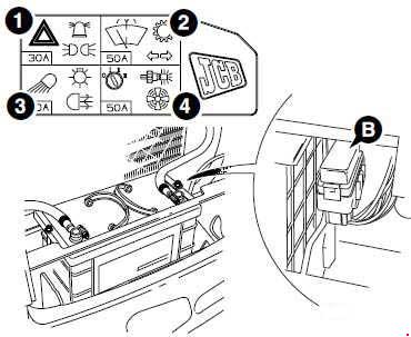
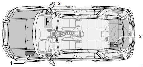
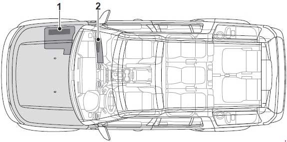
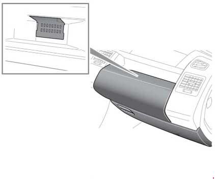
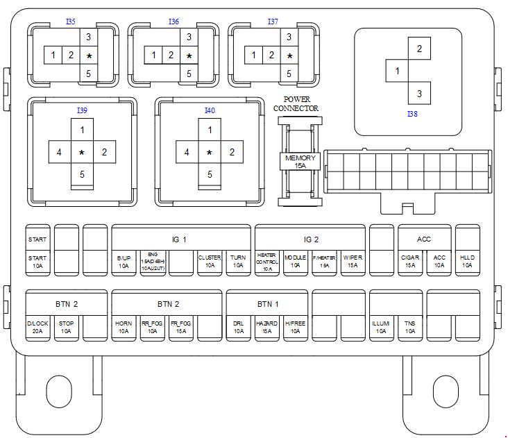
Location
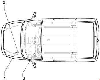
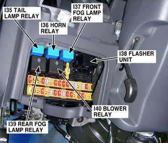
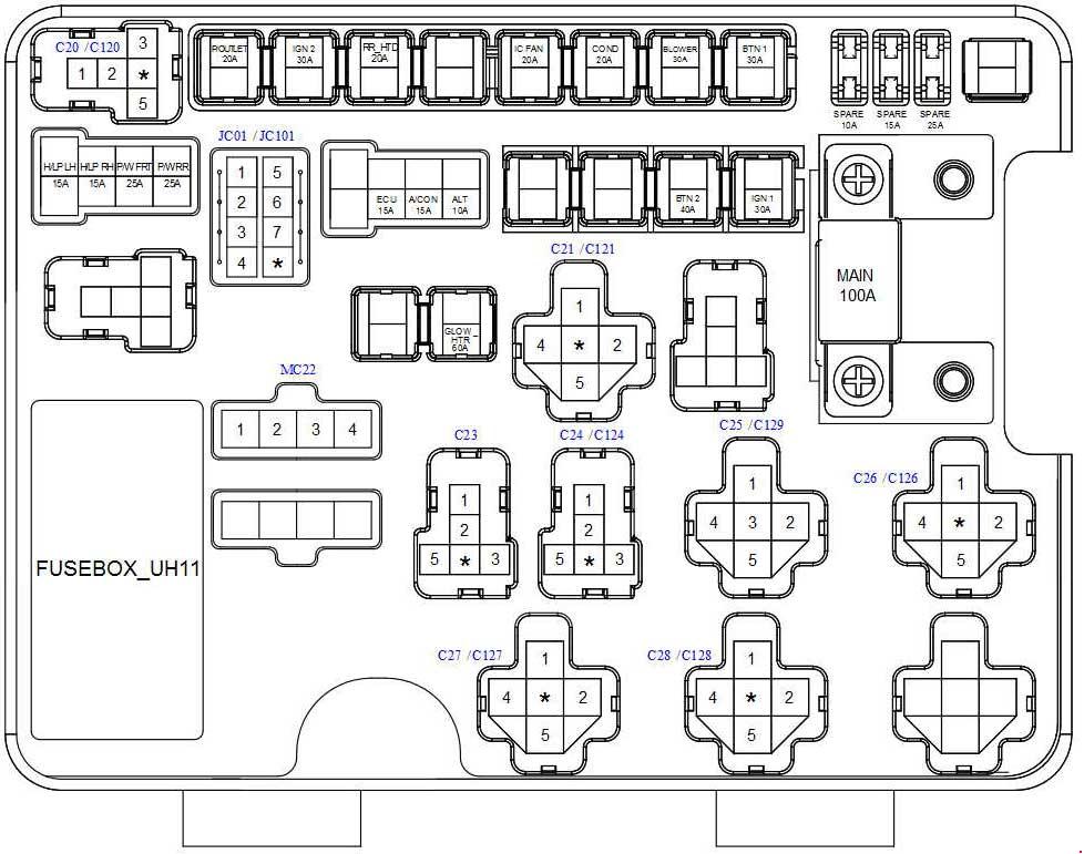
- Fuses on fuse holder A -SA- (On the electronics box, on left in engine compartment)
- Fuses on fuse holder B -SB- (On left in engine compartment)
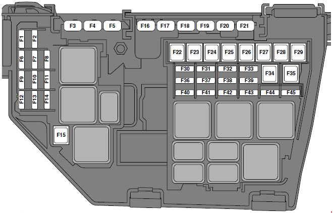
- Fuses on fuse holder C -SC- (Under left dash panel)
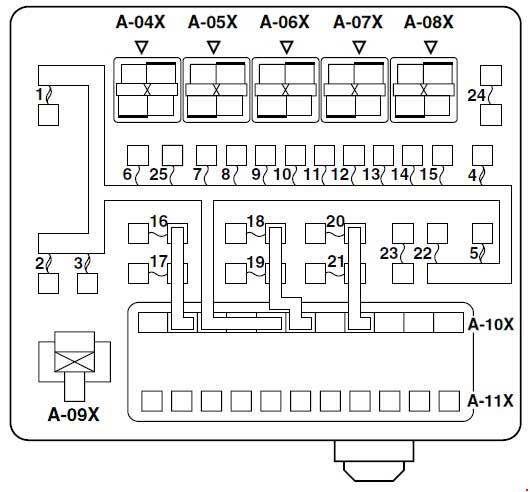
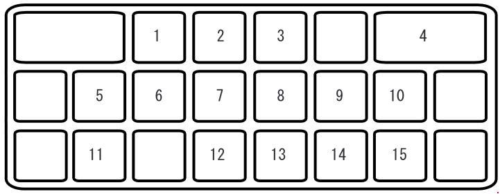
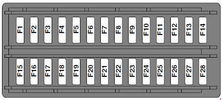
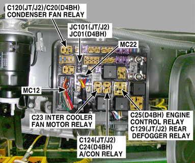
Fitting location of fuse holder A (A -SA-)
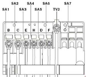
| No. | A | Function/component |
| 1 | 150 | Alternator -C- 90A / 110A |
| 1 | 200 | Alternator -C- 140A |
| 2 | 80 | Power steering control module -J500- Electromechanical power steering motor -V187- |
| 3 | 50 | Radiator fan control unit -J293- Radiator fan -V7- Right fan for coolant -V35- Radiator fan thermal switch -F18- Radiator fan -V7- |
| 4 | 502) 803) |
Onboard supply control unit -J519-2) X-contact relief relay -J59-2) Fuse 7 on fuse holder -SC7- Fuse 8 on fuse holder -SC8- Fuse 28 on fuse holder -SC28- to -SC33- |
| 5 | 100 | Fuses on fuse holder C -SC- Fuse 20 on fuse holder -SC20- to -SC24- Fuse 42 on fuse holder -SC42- to -SC52- |
| 6 | 40 | Low heat output relay -J359-4) Auxiliary air heater element -Z35- |
| 7 | 80 | High heat output relay -J360-4) Auxiliary air heater element -Z35- |
| 1) Only models with continuously variable radiator fan 2) Only models with central locking 3) Only models without central locking 4) Only models with auxiliary air heater (PTC) |
||
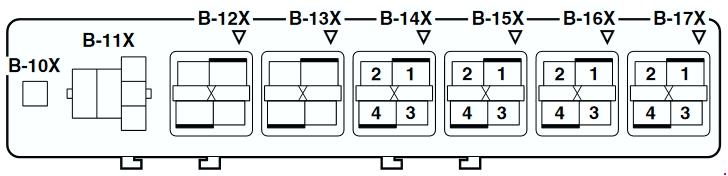
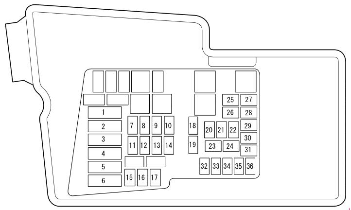
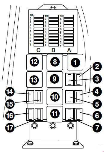
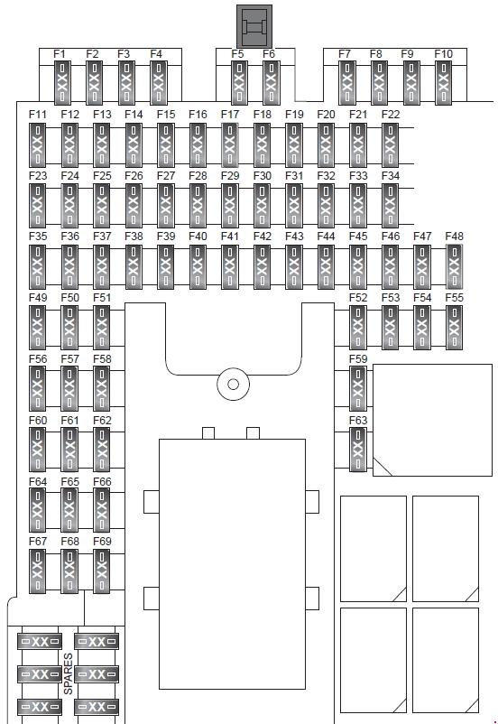
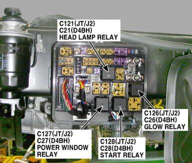
Fitting location of E-box high fuse holder (B -SB-)
| No. | A | Function/component |
| 1 | – | Not used |
| 2 | – | Not used |
| 3 | 5 | Onboard supply control unit -J519- |
| 4 | 30 | ABS Control Module -J104- |
| 5 | 15 | Mechatronics unit for dual clutch gearbox -J743- |
| 6 | – | Not used |
| 7 | 40 | Terminal 15 voltage supply relay 2 -J681- |
| 8 | 15 | Control module with display for radio and navigation system -J503- Radio -R- |
| 9 | 5 | Mobile telephone operating electronics control module -J412- Not used (from May 2009) |
| 10 | 10 | Motronic current supply relay -J271- (BUD, BSX) Term. 30 voltage supply relay -J317- (BDJ, BST, BLS, BMM, BSU, BJB) Engine control module -J623- (BSX, BUD) |
| 11 | 20 | Auxiliary heater control unit -J364- |
| 12 | 5 | Data bus diagnostic interface -J533- Not used (from May 2009) |
| 13 | 15 | Engine control module -J623- (BSX, BUD) Simos control module -J361- (BSE, BSF) |
| 13 | 30 | Diesel direct injection system control module -J248- (BDJ, BJB, BLS, BMM, BST, BSU) |
| 14 | 20 | Ignition coil 1 with output stage -N70- (BSX, BUD) Ignition coil 2 with output stage -N127- (BSX, BUD) Ignition coil 3 with output stage -N291- (BSX, BUD) Ignition coil 4 with output stage -N292- (BSX, BUD) Ignition transformer -N152- (BSE, BSF, BSX) |
| 15 | 5 | Fuel pump relay -J17- (BDJ, BJB, BLS, BMM, BST, BSU) Glow plug relay -J52- (BDJ, BST) Automatic glow period control module -J179- (BJB, BLS, BMM, BSU) |
| 15 | 10 | Fuel pump switch-off relay -J333- (BSX) Cylinder 1 injector -N30- (BUD) Cylinder 2 injector -N31- (BUD) Cylinder 3 injector -N32- (BUD) Cylinder 4 injector -N33- (BUD) Gas injector 1 -N366- (BSX) Gas injector 2 -N367- (BSX) Gas injector 3 -N368- (BSX) Gas injector 4 -N369- (BSX) |
| 16 | 30 | Onboard supply control unit -J519- , right headlight |
| 17 | – | Not used |
| 18 | 30 | Special vehicle control unit -J608- |
| 19 | 30 | Windscreen wiper motor -V- |
| 20 | 40 | Glow plug 3 -Q12- (BDJ, BST) Glow plug 4 -Q13- (BDJ, BST) |
| 20 | 10 | Tank shut-off valve 1 -N361- (BSX) (from May 2009) Tank shut-off valve 2 -N362- (BSX) (from May 2009) Tank shut-off valve 3 -N363- (BSX) (from May 2009) Tank shut-off valve 4 -N429- (BSX) (from May 2009) Tank shut-off valve 5 -N430- (BSX) (from May 2009) |
| 21 | 10 | Lambda probe heater -Z19- (BLS, BMM) |
| 21 | 15 | Lambda probe heater -Z19- (BSE, BSF, BSX, BUD) Lambda probe 1 heater after catalytic converter -Z29- (BSE, BSF, BSX, BUD) |
| 22 | 5 | Clutch position sender -G476- |
| 23 | 5 | Secondary air pump relay -J299- (BSE) Exhaust gas recirculation valve -N18- (BDJ, BST) |
| 23 | 10 | Exhaust gas recirculation valve -N18- (BJB, BSU) Charge pressure control solenoid valve -N75- (BJB, BLS, BMM, BSU) Exhaust gas recirculation cooler changeover valve -N345- (BJB, BLS, BMM, BSU) Tank shut-off valve 1 -N361- (BSX) (up May 2009) Tank shut-off valve 2 -N362- (BSX) (up May 2009) Tank shut-off valve 3 -N363- (BSX) (up May 2009) High-pressure valve for gas operation -N372- (BSX) Tank shut-off valve 4 -N429- (BSX) (up May 2009) |
| 24 | 10 | Cylinder 1 injector -N30- (BSX) Cylinder 2 injector -N31- (BSX) Cylinder 3 injector -N32- (BSX) Cylinder 4 injector -N33- (BSX) Activated charcoal filter solenoid valve 1 -N80- (BSE, BSF, BUD) Variable intake manifold changeover valve -N156- (BSE, BSF) Intake manifold flap motor -V157- (BDJ, BST) Radiator fan control unit -J293- Protective resistor -N235- |
| 25 | 40 | ABS Control Module -J104- |
| 26 | 40 | Onboard supply control unit -J519- , left headlight |
| 27 | 40 | Secondary air pump relay -J299- ( BSE) Secondary air pump motor -V101- Glow plug 1 -Q10- (BDJ, BST) Glow plug 2 -Q11- (BDJ, BST) |
| 27 | 50 | Automatic glow period control module -J179- (BJB, BLS, BMM, BSU) Glow plug 1 -Q10- Glow plug 2 -Q11- Glow plug 3 -Q12- Glow plug 4 -Q13- |
| 28 | – | Not used |
| 29 | 30 | Fuses on fuse holder C -SC- (special-purpose vehicles) Fuse 18 on fuse holder -SC18- Fuse 19 on fuse holder -SC19- Fuse 35 on fuse holder -SC35- to -SC39- Fuse 57 on fuse holder -SC57- Fuse 58 on fuse holder -SC58- |
| 30 | 50 | Fuses on fuse holder C -SC- (only with trailer coupling) (up May 2009) Fuse 39 on fuse holder -SC39- to -SC41- Fuses on fuse holder C -SC- (only with trailer coupling) (from May 2009) Fuse 40 on fuse holder -SC40- to -SC42- |
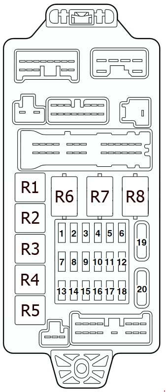
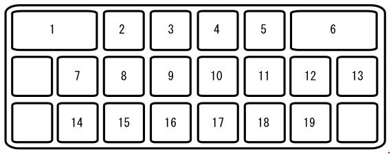
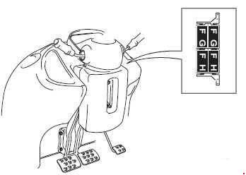
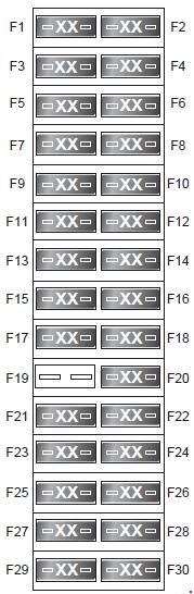
Position of fuses on fuse holder C -SC-
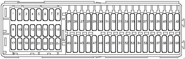
| No. | A | Function/component |
| 1 | – | Not used |
| 2 | – | Not used |
| 3 | – | Not used |
| 4 | – | Not used |
| 5 | – | Not used |
| 6 | – | Not used |
| 7 | – | Not used |
| 8 | – | Not used |
| 9 | 10 | 4-pin connector -T4g- (applies to special vehicles only) 10-pin connector -T10c- (for models with electric interface only) |
| 10 | 5 | Fuel pump relay -J17- (BSE, BSF, BUD, BSX) Terminal 15 voltage supply relay -J329- (BSE, BSF) Data bus diagnostic interface -J533- Engine control unit -J623- |
| 11 | 5 | Parking aid control unit -J446- (only models with parking aid) |
| 12 | 5 | Taxi meter -G41- (only taxi) Mirror taxi meter -G511- (only taxi) |
| 12 | 10 | 2-pin connector -T2ac- (applies to special vehicles only) 28-pin connector -T28a- (applies to special vehicles only) |
| 13 | 5 | Headlight range control regulator -E102- Left headlight range control motor -V48- Right headlight range control motor -V49- Traction control system switch -E132- TCS and ESP button -E256- Selector lever -E313- (only models with direct shift gearbox) Brake light switch -F- Brake light relay -J111- (only models without central locking) ABS control unit -J104- Trailer detector control unit -J345- Power steering control unit -J500- (only models with power steering) Selector lever sensors control unit -J587- (only models with direct shift gearbox) Mechatronic unit for dual clutch gearbox -J743- (only models with direct shift gearbox) Four-wheel drive control unit -J492- |
| 14 | 5 | Air mass meter -G70- (BLS, BSU, BJB, BDJ, BST, BMM, CHWA) Heater element for crankcase breather -N79- (BSE, BSF, BLS, BSU, BJB, BSX, BMM, CHWA) Reversing light switch -F4- Auxiliary heater operation relay -J485- (only models with auxiliary coolant heater) Activated charcoal filter system solenoid valve 1 -N80- (BSX) 16-pin connector -T16- (self-diagnosis connection) |
| 15 | 5 | Airbag control unit -J234- Front passenger side airbag deactivated warning lamp -K145- |
| 16 | 5 | Heater/heat output switch -E16- (only models without air conditioning system) High pressure sender -G65- (only models with air conditioning system) Oil level and oil temperature sender -G266- (only for models with flexible service interval display) Climatronic control unit -J255- (only models with Climatronic) Control unit in dash panel insert -J285- Low heat output relay -J359- (only models with PTC (Positive Temperature Coefficient) heater) High heat output relay -J360- (only models with PTC (Positive Temperature Coefficient) heater) Automatic anti-dazzle interior mirror -Y7- Air quality sensor -G238- (only models with Climatronic) |
| 17 | 7.5 | Left tail light and rear fog light bulb -M41- (models without central locking) Rear fog light cut-out contact switch -F216- (only models with trailer operation and without central locking) |
| 18 | 5 | Taxi alarm remote control, control unit -J601- (only taxi) 10-pin connector -T10c- (for models with electric interface only) |
| 19 | 5 | 10-pin connector -T10c- (for models with electric interface only) |
| 19 | 10 | Taxi meter -G41- (only taxi) Mirror taxi meter -G511- (only taxi) Two-way radio -R8- (only taxi) |
| 20 | 7.5 | Onboard supply control unit -J519- (Interior light) |
| 21 | 10 | Selector lever -E313- (only models with direct shift gearbox) Selector lever sensors control unit -J587- (only models with direct shift gearbox) Tiptronic switch -F189- (only models with direct shift gearbox) Automatic gearbox control unit -J217- 16-pin connector -T16- (self-diagnosis connection) Climatronic control unit -J255- (only models with Climatronic) Heater/heat output switch -E16- Air conditioning system control unit -J301- Remote control receiver for auxiliary coolant heater -R149- (only models with remote control receiver for auxiliary coolant heater) Light switch -E1- Rain and light detector sensor -G397- (models with rain and light detector sensor only) Control unit in dash panel insert -J285- Steering column electronics control unit -J527- Data bus diagnostic interface -J533- |
| 22 | 10 | Driver door control unit -J386- Front passenger door control unit -J387- |
| 23 | 5 | Interior light switch (taxi) -E115- (only taxi) Taxi sign switch -E138- (only taxi) Hands-free system button -E487- (only taxi) |
| 23 | 10 | 3-pin connector -T3r- (applies to special vehicles only) 10-pin connector -T10c- (for models with electric interface only) |
| 24 | 5 | Interior monitoring sensor -G273- Vehicle inclination sender -G384- Alarm horn -H12- |
| 25 | – | Not used |
| 26 | 10 | 2-pin connector -T2ab- (applies to special vehicles only) |
| 27 | 15 | Cut-out relay for air conditioning system magnetic coupling -J246- (only for models with hydraulic steering) |
| 28 | 5 | Light switch -E1- (models with central locking) |
| 28 | 20 | Rear fog light switch -E18- (only models without central locking) |
| 29 | 15 | Rear window wiper motor -V12- (models with rear window wiper only) |
| 30 | 25 | Light switch -E1- (only models without central locking) |
| 31 | 5 | Heater/heat output switch -E16- (only models without air conditioning system) Air conditioning system control unit -J301- (only models with air conditioning system) Climatronic control unit -J255- (only models with air conditioning system)Left washer jet heater element -Z20- Right washer jet heater element -Z21- |
| 32 | 15 | Windscreen and rear window washer pump -V59- |
| 33 | 40 | Heater/heat output switch -E16- Air conditioning system control unit -J301- Auxiliary heater operation relay -J485- (only models with auxiliary coolant heater) |
| 34 | – | Not used |
| 35 | 10 | Fluorescent light in rear of high roof -W41- (applies to special vehicles only) Fluorescent light in centre of high roof -W42- (applies to special vehicles only) |
| 36 | – | Not used |
| 37 | 15 | Right dipped beam bulb -M31- (models without central locking) |
| 38 | 15 | Left dipped beam bulb -M29- (models without central locking only) |
| 39 | 20 | 10-pin connector -T10ai- (applies to special vehicles only) |
| 40 | 20 | Trailer detector control unit -J345- |
| 41 | 20 | Trailer detector control unit -J345- |
| 42 | 20 | Trailer detector control unit -J345- |
| 43 | 15 | Electric fuel pump 2 relay -J49- (BSE, BSF, BUD, BSX) Fuel pump relay -J17- (BDJ, BST, BLS, BSU, BJB, BSE, BSF, BUD, BSX, BMM) |
| 44 | 40 | Fresh air blower control unit -J126- |
| 45 | 20 | Headlight washer system relay -J39- (only models with headlight washer system) Headlight washer system pump -V11- (only models with headlight washer system) |
| 46 | 15 | Treble tone horn -H2- Bass tone horn -H7- Horn relay -J413- |
| 47 | 25 | Cigarette lighter -U1- |
| 48 | 30 | Heated front seats control unit -J774- |
| 49 | 30 | Driver door control unit -J386- (only for model with electric window regulator) Front passenger door control unit -J387- (only for model with electric window regulator) |
| 50 | 25 | Convenience system central control unit -J393- |
| 51 | 30 | 10-pin connector -T10ai- (applies to special vehicles only) |
| 52 | 25 | Fresh air blower relay -J13- (only models with auxiliary heater) Onboard supply control unit -J519- Heated rear window -Z1- |
| 53 | 15 | 12 V socket -U5- (near handbrake lever) |
| 53 | 30 | 12 V socket -U5- (near handbrake lever) 12 V socket 2 -U18- (left luggage compartment) |
| 54 | – | Not used |
| 55 | – | Not used |
| 56 | – | Not used |
| 57 | 5 | 2-way radio switch -E72- (applies to special vehicles only) Engine continues to run without key button -E489- (applies to special vehicles only) Accident data memory -J754- (applies to special vehicles only) 10-pin connector -T10c- (for models with electric interface only) |
| 58 | 10 | 4-pin connector -T4g- (applies to special vehicles only) |
| 59 | – | Not used |
| 60 | – | Not used |
WARNING: Terminal and harness assignments for individual connectors will vary depending on vehicle equipment level, model, and market.