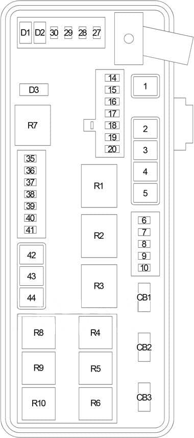
| No. |
A
|
Protected Component |
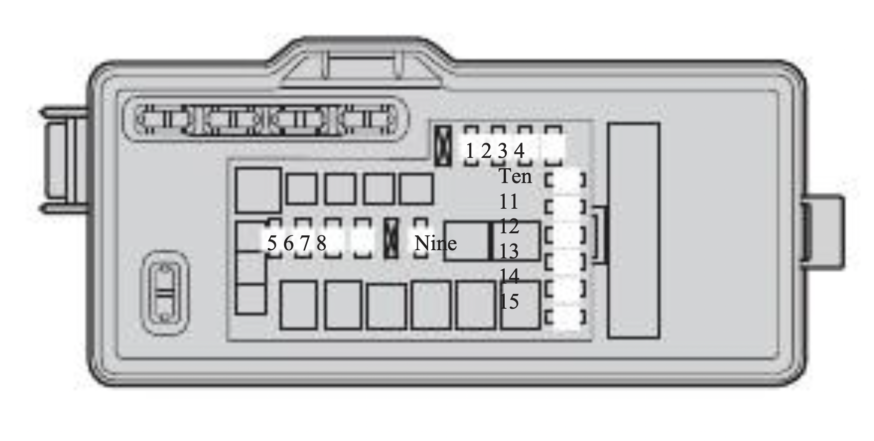
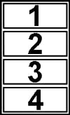
| 1 |
60 |
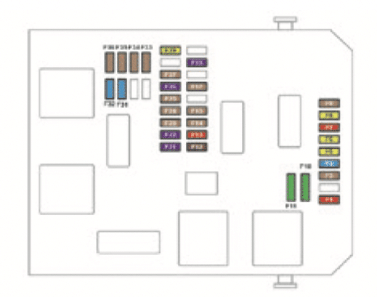
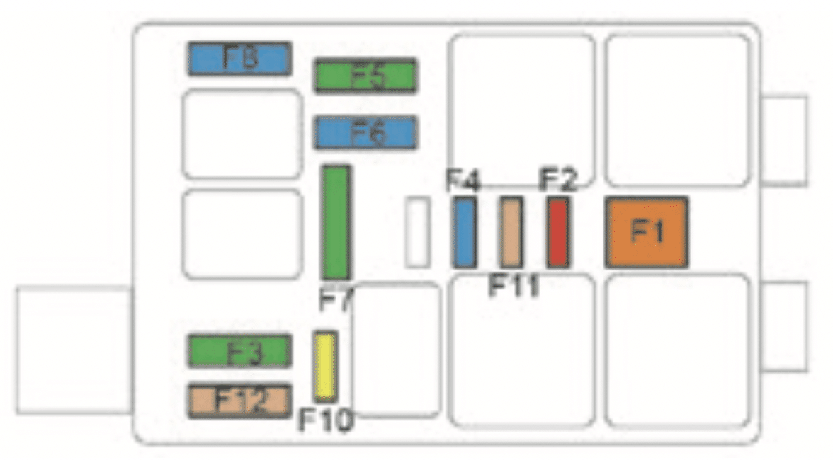
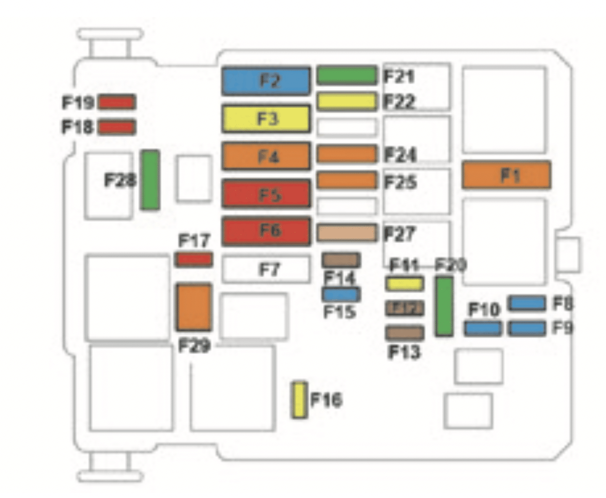
Fuse (Luggage Compartment): “14”, “36”, “38”, “44” |
| 2 |
40 |
Engine Compartment Fuse Box (Fusible Link 14) |
| 3 |
20 |
Police: Dome Lamp |
| 4 |
40 |
Engine Compartment Fuse Box (Fusible Link 14) |
| 5 |
30 |
except for SRT8: Heated Seat Module, Zener Diode, Fuse (Luggage Compartment): “30” |
| 40 |
SRT8: Heated Seat Module, Zener Diode, Fuse (Luggage Compartment): “30” |
| 6 |
20 |
Fuel Pump Relay |
| 7 |
20 |
SRT8: Subwoofer Amplifier |
| 15 |
Police: Spot Lamp (Right) |
| 8 |
15 |
Data Link Connector, Occupant Classification System (LHD), Ignition Switch (Engine Control Module (Diesel), Powertrain Control Module, Lock Steering Column Module (RHD), Fuel Pump Relay (Gasoline), Fuse (Luggage Compartment): “27”, “29”, “40”, Diode No.1) |
| 9 |
20 |
Power Outlet – Console |
| 10 |
10 |
Export: Rear Fog Lamp Relay |
| 15 |
Police: Spot Lamp (Left) |
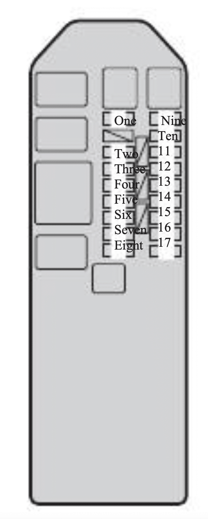
| 14 |
10 |
A/C / Heater Control, Sentry Key Remote Entry Module (LHD), Cluster, Intrusion Transceiver Module (RHD) |
| 15 |
20 |
Brake Module (Trailer Tow) |
| 16 |
20 |
Magnum (300C Touring): Rear Power Outlet |
| 17 |
20 |
Cluster, Lock Steering Column Module (RHD), Sentry Key Remote Entry Module (RHD) |
| 18 |
20 |
Cigar Lighter |
| 19 |
10 |
Stop Lamp Switch, Stop Lamp Inhibit Relay (except MK25E) |
| 20 |
20 |
Magnum (300C Touring): Rear Wiper Relay |
| 27 |
10 |
Occupant Classification System, Occupant Restraint Controller Module |
| 28 |
10 |
except for SRT8: Occupant Restraint Controller Module |
| 5 |
SRT8: Occupant Restraint Controller Module |
| 29 |
5 |
Stop Lamp Switch, Cluster, Sentry Key Remote Entry Module, Mass Air Flow Sensor (Diesel), ABS, Front Control Module, Powertrain Control Module (Gasoline), Engine Control Module (Diesel) |
| 30 |
10 |
Driver/Passenger Door Module, Mirror Switch, Steering Control Module, Police/Taxi Interface Module |
| 35 |
5 |
Mirror Switch (except Memory), Passenger Express Window/Door Lock Switch (except Base), Backlite Antenna Amplifier, Headlamp Flasher (Police), Police Relay No.1, Police Relay No.2, Police Relay No.3, Electronic Overhead Module (Export), Rain Sensor (Export) |
| 36 |
20 |
Radio, Hands-Free Module, Satellite Receiver, Monitor/DVD Media System, Traffic Information Receiver Module (Export) |
| 37 |
15 |
NAG1: Transmission Control Module |
| 38 |
5 |
Cargo Lamp (except Magnum), Analog Clock Module, Electronic Overhead Module, Siren (RHD) |
| 39 |
10 |
Heated Mirror |
| 40 |
5 |
except for SRT8: Left/Right Heated Seat Switch, A/C Heater Control, Inside Rearview Mirror |
| 10 |
SRT8: Left/Right Heated Seat Switch, A/C Heater Control, Inside Rearview Mirror |
| 5 |
Police: Bank Switch |
| 41 |
10 |
A/C Heater Control, Tire Pressure Monitor, Left/Right Headlamp Level Sensor (Export), Parl Assist Module, Headlamp Leveling Module (Export), Left/Right High-Intensity Discharge Lamp (Export) |
| 42 |
30 |
Front Blower Motor (MTC), Front Blower Module (ATC) |
| 43 |
30 |
Rear Window Defogger |
| 44 |
20 |
Front Control Module, Sunroof Motor/Module, Radio Amplifier |
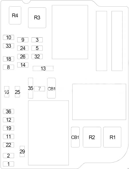
| Circuit Breaker |
| CB1 |
25 |
Driver Seat Switch (except Memory), Memory Seat Module, Cluster (except Power/Memory Seat) |
| CB2 |
25 |
Passenger Seat Switch |
| CB3 |
25 |
except for SRT8:Driver/Passenger Window/Door Lock Switch (Base), Driver/Passenger Door Module (except Base), Driver Express Window/Door Lock Switch (except Base) |
| 30 |
SRT8:Driver/Passenger Window/Door Lock Switch (Base), Driver/Passenger Door Module (except Base), Driver Express Window/Door Lock Switch (except Base) |
| Diode |
| D1 |
NAG1: Transmission Control Relay |
| D2 |
Front Control Module |
| D3 |
Zener |
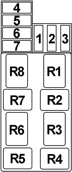
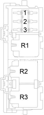
| Relay |
| R1 |
Run |
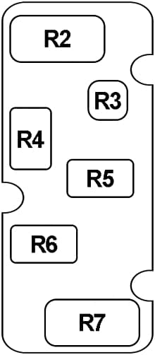
| R2 |
Rear Window Defogger |
| R3 |
Accessory Delay |
| R4 |
NAG1: Transmission Control |
| R5 |
Export: Rear Fog Lamp |
| R6 |
Magnum (300C Touring): Rear Wiper |
| R7 |
– |
| R8 |
Stop Lamp Inhibit (except MK25E) |
| R9 |
Fuel Pump |
| R10 |
– |