Toyota Yaris Verso (1999 – 2005) – fuse box diagram
Year of production: 1999, 2000, 2001, 2002, 2003, 2004, 2005
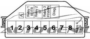
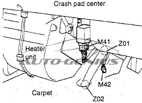
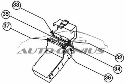
Passenger Compartment
LHD
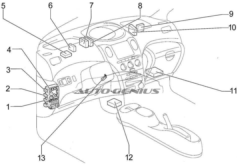
- Front Fog Light Relay
- Defogger Relay
- Taillight Relay
- Fuse Box
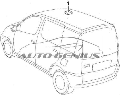
- Wireless Door Lock Control Receiver
- Active Light Relay
- Daytime Running Light Relay
- Door Lock Control Relay
- A/C Amplifier
- PTC Amplifier
- Engine and ECT ECU (A/T) or Engine ECU (M/T)
- Center Airbag Sensor Assembly
- Transponder Key Amplifier
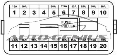
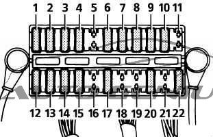
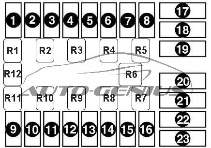
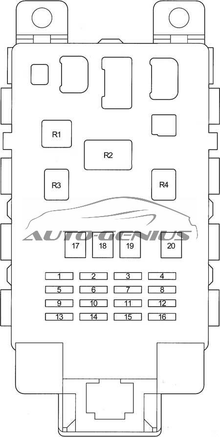
Passenger Compartment Fuse Box
| No. | Fuse | A |
Circuits |
| 1 | GAUGE | 10 | ABS, Air Conditioner, Back-Up Light, Charging, Combination Meter, Door Lock Control, Double Locking, ECT, Engine Control, Headlight (w/ Daytime Running Light), Light Reminder Buzzer, Moon Roof, Power Window, Shift Lock, Turn Signal and Hazard Warning Light, Two Way Flow Heater, Wireless Door Lock Control |
| 2 | DEF RLY | 10 | Rear Window Defogger and Mirror Heater |
| DEF | 20 | Rear Window Defogger and Mirror Heater | |
| 3 | D/L | 25 | Double Locking, Wireless Door Lock Control |
| 4 | TAIL | 7,5 | Front Fog Light, Headlight, Headlight Beam Level Control, Light Reminder Buzzer, Rear Fog Light, Taillight and Illumination |
| 5 | — | — | — |
| 6 | WIPER | 20 | Front Wiper and Washer, Rear Wiper and Washer, Door Lock Control |
| 7 | ECU-B | 7,5 | Headlight, Rear Fog Light |
| 8 | FOG | 15 | Front Fog Light |
| 9 | ACC | 15 | Cigarette Lighter, Clock, Combination Meter, Light Reminder Buzzer, Multi Display, Power Outlet, Radio and Player, Remote Control Mirror |
| 10 | ECU-IG | 7,5 | ABS, Interior Light, Multi Display, PTC Heater, Radiator Fan and Condenser Fan, SRS, Two Way Flow Heater |
| 11 | OBD | 7,5 | On-board diagnosis system |
| 12 | HAZ | 10 | Turn Signal and Hazard Warning Light |
| 13 | A.C | 7,5 | Air Conditioner, Two Way Flow Heater |
| 14 | S-HTR | 10 | Seat Heater |
| 15 | — | — | — |
| 16 | STOP | 10 | ECT, Engine Control, Shift Lock, Stop Light |
| 17 | AM1 | 50 | “ACC”, “GAUGE”, “DEF” (“DEF RLY”), “S-HTR”, “WIPER”, and “ECU-IG” fuses |
| 18 | POWER | 30 | Moon Roof, Power Window |
| 19 | HTR | 40 | Air Conditioner, Two Way Flow Heater |
| 20 | DEF | 30 | Rear Window Defogger and Mirror Heater |
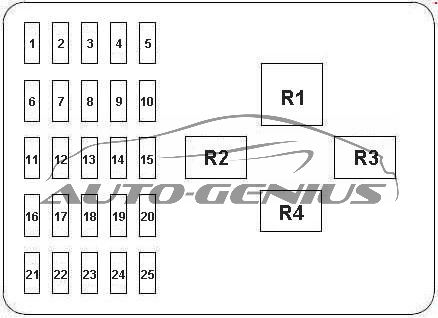
| Relay | |||
| R1 | Heater | ||
| R2 | Flasher | ||
| R3 | Power | ||
| R4 | Circuit Opening Relay (C/OPN) | ||
- Moon Roof Control SW and Moon Roof Control Relay
Engine Compartment
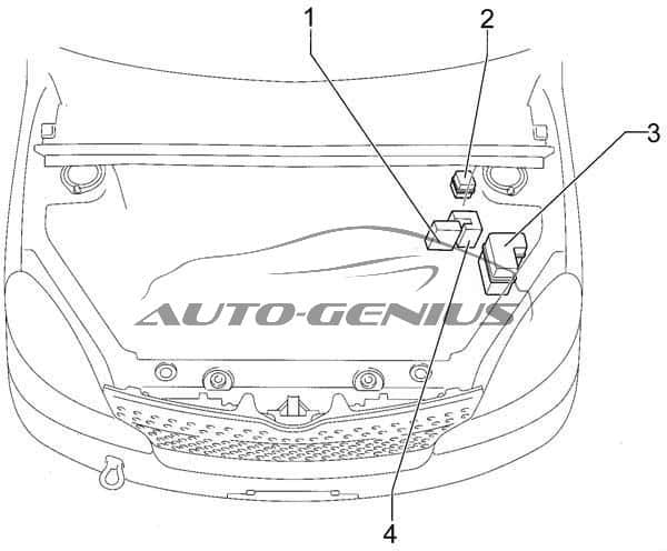
- Fusible Link Block
- Additional Fuse Box
- Fuse Box
- ABS Actuator with ECU
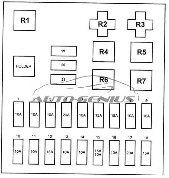
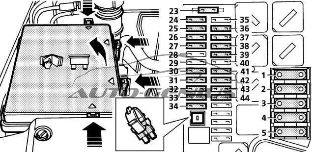
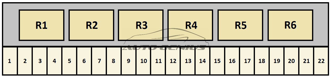
Engine Compartment Fuse Box
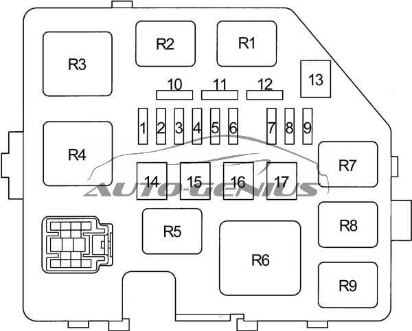
| No. | Fuse | A |
Circuits |
| 1 | DOME | 15 | Clock, Combination Meter, Double Locking, Headlight, Interior Light, Light Reminder Buzzer, Multi Display, Radio and Player, Wireless Door Lock Control |
| 2 | EFI | 15 | ECT, Engine Control, Engine Immobiliser System |
| 3 | HORN | 15 | Horn |
| 4 | AM2 | 15 | Charging, Combination Meter, ECT, Engine Control, Multi Display, SRS, Starting and Ignition |
| 5 | ST | 30 | Starting and Ignition |
| 6 | — | — | — |
| 7 | H-LP LH | 10 | Left-hand Headlight, Headlight Beam Level Control (with Daytime Running Light) |
| H-LP LO LH | 10 | Left-hand Headlight, Headlight Beam Level Control (with Daytime Running Light) | |
| 8 | H-LP RH | 10 | Right-hand Headlight, Headlight Beam Level Control (with Daytime Running Light) |
| H-LP LO RH | 10 | Right-hand Headlight, Headlight Beam Level Control (with Daytime Running Light) | |
| 9 | P/POINT | 15 | Power Outlet |
| 10 | — | — | Spare |
| 11 | — | — | Spare |
| 12 | — | — | Spare |
| 13 | — | — | — |
| 14 | — | — | — |
| 15 | RDI | 30 | Radiator Fan and Condenser Fan |
| 16 | HTR SUB1 | 50 | PTC Heater |
| 17 | — | — | — |
| Relay | |||
| R1 | Electric cooling fan | ||
| R2 | Electric cooling fan | ||
| R3 | Starter | ||
| R4 | — | ||
| R5 | Power Outlet | ||
| R6 | PTC Heater | ||
| R7 | EFI | ||
| R8 | Magnetic clutch (A/C) | ||
| R9 | Horn | ||
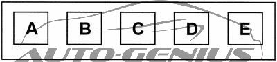
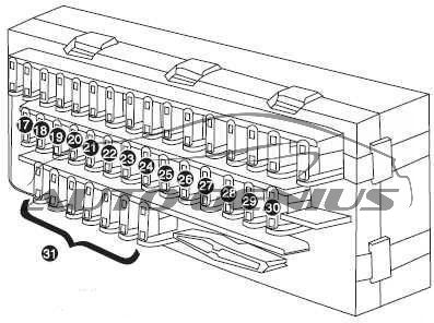
Additional Fuse Box
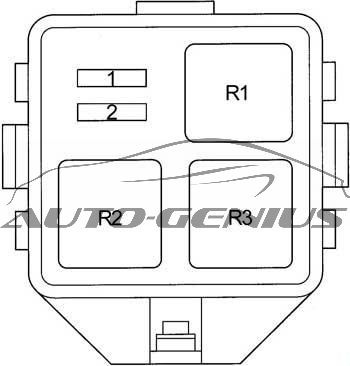
| No. | Fuse | A |
Circuits |
| 1 | H-LP HI RH | 10 | Headlight (with Daytime Running Light) |
| 2 | H-LP HI LH | 10 | Combination Meter, Headlight (with Daytime Running Light) |
| Relay | |||
| R1 | Headlight | ||
| R2 | Dimmer (DIM) | ||
| R3 | — | ||
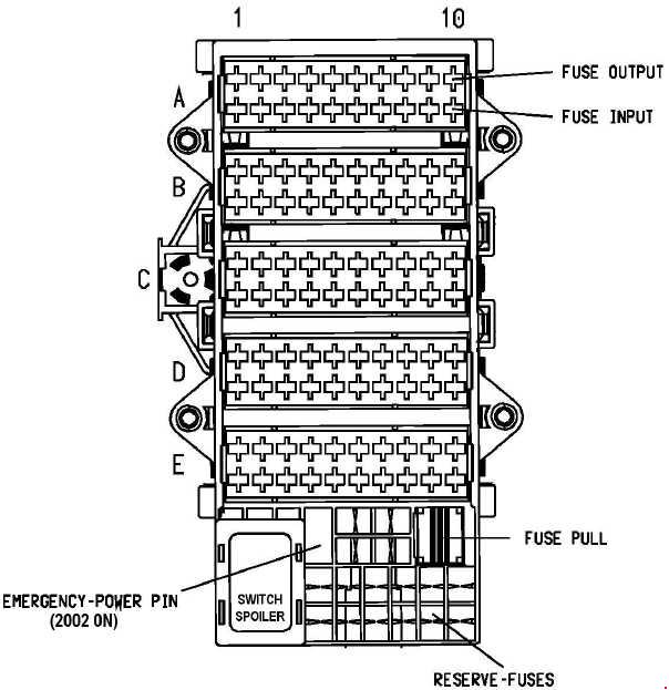
Fusible Link Block
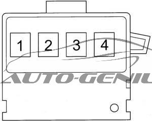
| No. | Fuse | A |
Circuits |
| 1 | MAIN | 60 | “EFI”, “DOME”, “HORN”, “ST”, “AM2”, “H-LP LH”, “H-LP RH”, “H-LP LH (HI)”, “H-LP RH (HI)”, “H-LP LH (LO)” and “H-LP RH (LO)” fuses |
| 2 | — | — | — |
| 3 | ALT | 120 | “ECU-B”, “TAIL”, “D/L”, “OBD”, “RDI”, “AM1”, “HAZ”, “HTR”, “HTR-SUB1”, “POWER”, “STOP” and “DEF” fuses |
| 4 | ABS | 60 | Anti-lock brake system |
WARNING: Terminal and harness assignments for individual connectors will vary depending on vehicle equipment level, model, and market.