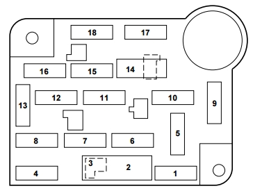
| No. |
A |
Designation |
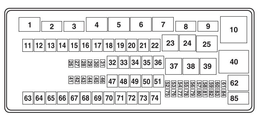
| 1 |
10 |
’15-’16: Demand lighting (glove box, vanity, dome), Battery saver relay coil, Second row easy fold relay coil |
| 2 |
7.5 |
’15-’20: Memory seats, Lumbar, Power mirrors (’16 – MKX), Driver seat module logic power (’15-’18), Wireless charger (’19-20) |
| 10 |
’21-’22: Delayed accessory – power inverter logic, moonroof logic and driver window switch power |
| 3 |
20 |
’15-’20: Driver door unlock |
| 7.5 |
’21-’22: Memory seats, Lumbar, Wireless accessory charging |
| 4 |
20 |
’21-’22: Subwoofer amplifier |
| 5 |
20 |
’15-’20: Subwoofer amplifier |
| 6 |
10 |
MKX, Nautilus (’19-’20): USB charger |
| 10 |
Nautilus (’21-’22): Security horn relay
|
| 7 |
10 |
’21-’22: Gearshift module |
| 8 |
10 |
’17-’20 (MKX, Nautilus): Security horn relay |
| 5 |
’21-’22: Power liftgate module, Hands free liftgate module, Embedded modem |
| 9 |
10 |
MKX, Nautilus (’19-’20): Rear seat entertainment system module, 360 camera badge (except Nautilus) |
| 5 |
’21-’22: Keypad, Combined sensing module (Nautilus) |
| 10 |
5 |
’15-’20: Keypad, Power liftgate module logic power, Handsfree liftgate module, MyLincoln module (’16), SYNC 3 module (’17-’18), Embedded modem |
| 11 |
5 |
’17-’20 (MKX, Nautilus): Combined sensing module |
| 5 |
Edge (EU): Combined security module |
| 12 |
7.5 |
Climate control module, Gear shift module (’17-’18 MKX; ’19-’20), Enhanced central gateway module (’21-’22) |
| 13 |
7.5 |
Instrument cluster, Steering column control module, Smart datalink connector (gateway) module (’15-’20) |
| 14 |
10 |
’17-’20: Extended power module – power |
| 15 |
10 |
’15-’20: Datalink power |
| 15 |
’21-’22: SYNC module |
| 16 |
15 |
Edge (EU): Child lock |
| 17 |
7.5 |
’21-’22: Headlamp control module |
| 5 |
Edge (EU): Battery backed sounder
|
| 18 |
5 |
’15-’20: Ignition switch (MKX), Push button start switch (except Nautilus), Key inhibit solenoid (MKX) |
| 19 |
7.5 |
’17-’20: Extended power module – Run/Start |
| 5 |
’21-’22 (Nautilus): Headlamp switch, Bluetooth low energy module |
| 20 |
7.5 |
MKX: Active front steering logic power |
| 7.5 |
Edge (EU): Headlamp control module, Adaptive front steering
|
| 7.5 |
Nautilus (’19-’20): Headlamp control module |
| 5 |
’21-’22: Push button ignition switch
|
| 21 |
5 |
Humidity and in-car temperature sensor |
| 22 |
5 |
’15-’20: Occupant classification sensor (except Nautilus, Edge (Eu)) |
| 23 |
10 |
’15-’20: Delayed accessory (power inverter logic, moonroof logic, driver window switch power), Heads up display (’16 – MKX), Gear shift module (’16 – MKX), Front camera (’16 – MKX), 360 camera module (’16 – MKX) |
| 30 |
’21-’22: Driver door window and mirror, Driver door module, Driver door lock indicator, Driver lock switch illumination |
| 24 |
20 |
’15-’20: Central lock unlock |
| 30 |
’21-’22: Moonroof |
| 25 |
30 |
’15-’20: Driver door (window, mirror), Driver door module, Driver door lock indicator, Driver lock switch illumination |
| 20 |
’21-’22: Amplifier |
| 26 |
30 |
Front passenger door (window, mirror), Front passenger door module, Front passenger lock indicator, Front passenger switch illumination (window, lock) |
| 27 |
30 |
’15-’20: Moonroof |
| 30 |
’21-’22 (Nautilus): Left-hand rear door module
|
| 28 |
20 |
’15-’20: Amplifier |
| 30 |
’21-’22 (Nautilus): Right-hand rear door module
|
| 29 |
30 |
MKX, Nautilus (’19-’20): Rear driver side door smart window |
| 30 |
Edge (EU): Rear left door (window)
|
| 15 |
’21-’22: Enhanced central gateway power – OBD connector
|
| 30 |
30 |
MKX, Nautilus (’19-’20): Rear passenger side door smart window |
| 30 |
Edge (EU): Rear right door (window)
|
| 31 |
10 |
’21-’22: Radio transceiver module, Multi-function display, Integrated control panel |
| 32 |
10 |
’15-’20: Global positioning system module, Centerstack display (except Nautilus), Voice control (SYNC), Radio transceiver module, Multimedia gateway module (’16 – MKX) |
| 20 |
’21-’22: Radio |
| 33 |
20 |
’15-’20: Radio |
| 34 |
30 |
’15-’20: Run-start bus (fuse 19, 20, 21, 22, 35,36, 37, circuit breaker 38) |
| 30 |
’21-’22: Run-start bus (fuse 17, 18, 21, 22, 35, 36, 37, circuit breaker 38) |
| 35 |
5 |
’15-’16: Restraints control module |
| 5 |
’21-’22: Passenger airbag deactivation indicator |
| 36 |
15 |
’15-’20: Auto-dimming rearview mirror, Heated seat (’15-’18), Auto high beam/lane departure mirror module, Rear heated seat module logic power, Suspension module (MKX, Nautilus) |
| 15 |
’21-’22: Rear heated seat module, Suspension module (Nautilus) |
| 37 |
20 |
Heated steering wheel module (without active front steering), Active front steering wheel (Edge, Nautilus), Auto-dimming interior mirror (’21-’22), Automatic high beam and lane departure mirror module (’21-’22), Parking assist control module (’21-’22 – Nautilus) |
| 15 |
’15 (Edge): Heated steering wheel module |
| 38 |
30 |
except Edge (EU): Rear power windows, Rear window switch illumination |