Chevrolet Avalanche (2007) – fuse box diagram
Year of production: 2007
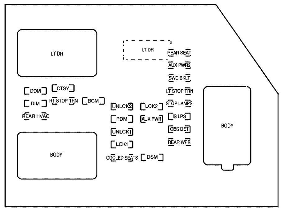
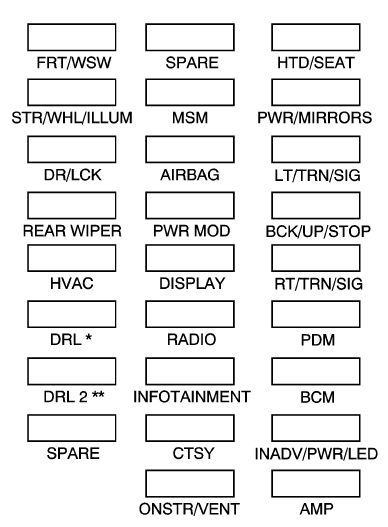
Instrument Panel Fuse Block
The instrument panel fuse block access door is located on the driver side edge of the instrument panel.
Chevrolet Avalanche – fuse box diagram – instrument panel
Fuses
Usage
LT DR
Driver’s Side Power Window Circuit Breaker
REAR SEAT
Rear Seats
AUX PWR2
Rear Cargo Area Power Outlets
SWC BKLT
Steering Wheel Controls Backlight
DDM
Driver Door Module
CTSY
Dome Lamps, Driver’s Side Turn Signal
LT STOP TRN
Driver’s Side Turn Signal, Stoplamp
DIM
Instrument Panel Back Lighting
RT STOP TRN
Passenger’s Side Turn Signal, Stoplamp
BCM
Body Control Module
UNLCK2
Power Door Lock 2 (Unlock Feature)
LCK2
Power Door Lock 2 (Lock Feature)
STOP LAMPS
Stoplamps, Center-High Mounted Stoplamp
REAR HVAC
Rear Climate Controls
PDM
Passenger Door Module, Universal Home Remote System
AUX PWR
Accessory Power Outlets
IS LPS
Interior Lamps
UNLCK1
Power Door Lock 1 (Unlock Feature)
OBS DET
Ultrasonic Rear Parking Assist, Power Liftgate
LCK1
Power Door Lock 1 (Lock Feature)
REAR WPR
Rear Wiper
COOLED SEATS
Not Used
DSM
Driver Seat Module, Remote Keyless Entry System
Harness connector
Usage
LT DR
Driver Door Harness Connection
BODY
Harness Connector
BODY
Harness Connector
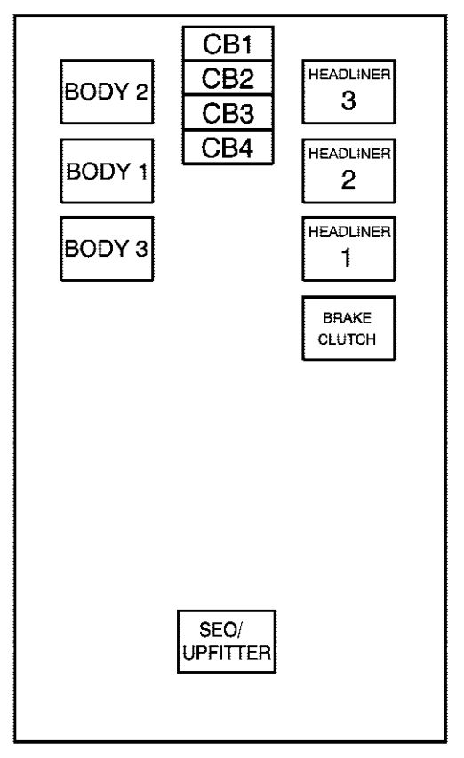
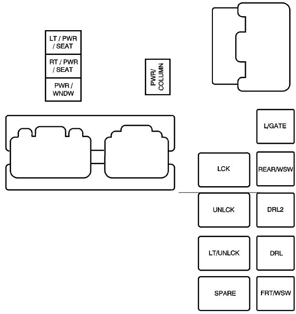
Center Instrument Panel Fuse Block
The center instrument panel fuse block is located underneath the instrument panel, to the left of the steering column.
Top View
Chevrolet Avalanche –
Harness connector
Usage
BODY 2
Body Harness Connector 2
BODY 1
Body Harness Connector 1
BODY 3
Body Harness Connector 3
HEADLINER 3
Headliner Harness Connector 3
HEADLINER 2
Headliner Harness Connector 2
HEADLINER 1
Headliner Harness Connector 1
BRAKE CLUTCH
Brake Clutch Harness Connector
SEO/UPFITTER
Special Equipment Option Upfitter Harness Connector
Circuit breaker
Usage
CB1
Passenger’s Side Power Window Circuit Breaker
CB2
Passenger’s Seat Circuit Breaker
CB3
Driver’s Seat Circuit Breaker
CB4
Not Used
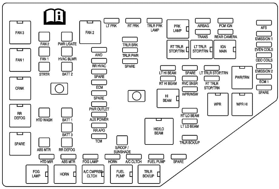
Underhood Fuse Block
The underhood fuse block is located in the engine compartment, on the driver side of the vehicle. Lift the cover for access to the fuse/relay block.
Chevrolet Avalanche – fuse box diagram – engine compartment
Fuses
Usage
1
Not Used
2
Electronic Stability Suspension Control, Automatic Level Control Exhaust
3
Left Trailer Stop/Turn Lamp
4
Engine Controls
5
Engine Control Module, Throttle Control
6
Right Trailer Stop/Turn Lamp
7
Front Washer
8
Oxygen Sensors
9
Antilock Brakes System 2
10
Trailer Back-up Lamps
11
Driver Side Low-Beam Headlamp
12
Engine Control Module (Battery)
13
Fuel Injectors, Ignition Coils (Right Side)
14
Transmission Control Module (Battery)
15
Vehicle Back-up Lamps
16
Passenger Side Low-Beam Headlamp
17
Air Conditioning Compressor
18
Oxygen Sensors
19
Transmission Controls (Ignition)
20
Fuel Pump
21
Not Used
22
Rear Washers
23
Fuel Injectors, Ignition Coils (Left Side)
24
Trailer Park Lamps
25
Driver’s Side Park Lamps
26
Passenger’s Side Park Lamps
27
Fog Lamps
28
Horn
29
Passenger Side High-Beam Headlamp
30
Daytime Running Lamps
31
Driver Side High-Beam Headlamp
32
Not Used
33
Sunroof
34
Key Ignition System, Theft Deterrent System
35
Windshield Wiper
36
SEO B2 Upfitter Usage (Battery)
37
Electric Adjustable Pedals
38
Climate Controls (Battery)
39
Airbag System (Ignition)
40
Amplifier
41
Audio System
42
Four-Wheel Drive
43
Miscellaneous (Ignition), Rear Vision Camera, Cruise Contro
44
Liftgate Release
45
OnStar®, Rear Seat Entertainment Display
46
Instrument Panel Cluster
47
Not Used
48
Not Used
49
Auxiliary Climate Control (Ignition), Compass-Temperature Mirror
50
Rear Defogger
51
Airbag System (Battery)
52
SEO B1 Upfitter Usage (Battery)
53
Cigarette Lighter, Auxiliary Power Outlet
54
Automatic Level Control Compressor Relay, SEO Upfitter Usage
55
Climate Controls (Ignition)
56
Engine Control Module, Secondary Fuel Pump (Ignition)
J-Case Fuses
Usage
60
Cooling Fan 1
61
Automatic Level Control Compressor
62
Heavy Duty Anti-lock Brake System
63
Cooling Fan 2
64
Anti-lock Brake System 1
65
Starter
66
Stud 2 (Trailer Brakes)
67
Left Bussed Electrical Center 1
68
Electric Running Boards
69
Heated Windshield Washer System
70
Four-Wheel Drive System
71
Stud 1 (Trailer Connector Battery Power)
72
Mid-Bussed Electrical Center 1
73
Climate Control Blower
74
Power Liftgate Module
75
Left Bussed Electrical Center 2
Relays
Usage
FAN HI
Cooling Fan High Speed
FAN LO
Cooling Fan Low Speed
ENG EXH VLV
Not Used
FAN CNTRL
Cooling Fan Control
HDLP LO/HID
Low-Beam Headlamp
FOG LAMP
Front Fog Lamps
A/C CMPRSR
Air Conditioning Compressor
STRTR
Starter
PWR/TRN
Powertrain
FUEL PMP
Fuel Pump
PRK LAMP
Parking Lamps
REAR DEFOG
Rear Defogger
RUN/CRANK
Switched Power
WARNING: Terminal and harness assignments for individual connectors will vary depending on vehicle equipment level, model, and market.