KIA Carens (RD; from 2013) – fuse box diagram
Also called: KIA Rondo
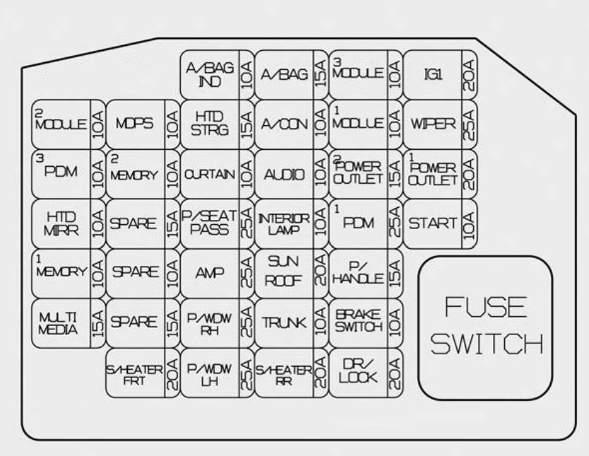
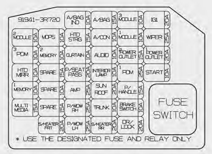
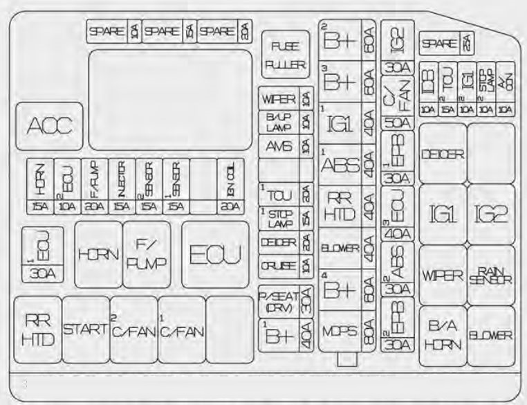
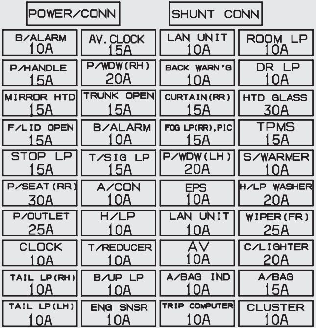
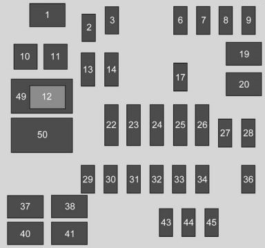
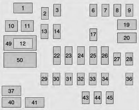
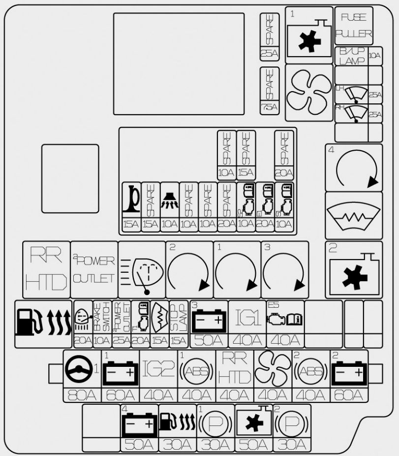
Inner fuse panel
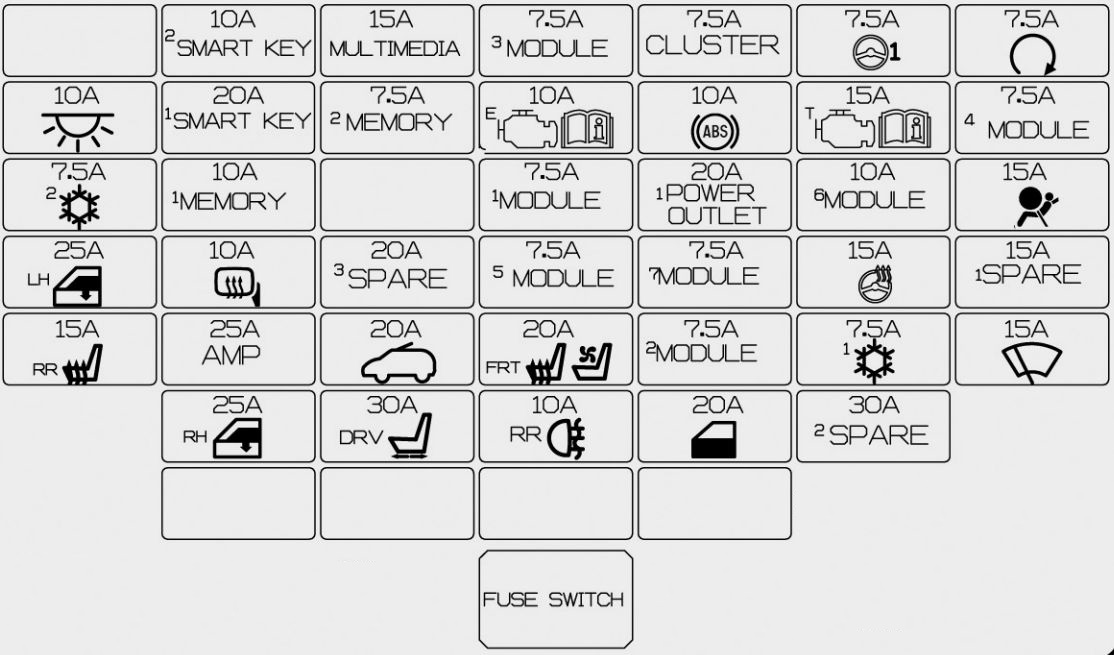
| No. | Fuse rating | Symbol | Fuse name | Protected component |
| 1 | 30 |  |
P/SEAT DRV | 4WAY : Driver Lumbar Support Switch 6WAY : Driver Seat Manual Switch |
| 2 | 25 |  |
P/WDW RH | Power Window Relay RH, Driver/Passenger Safety Power Window Module, Rear Safety Power Window Module RH |
| 3 | 25 |  |
P/WDW LH | Power Window Relay LH, Driver/Passenger Safety Power Window Module, Rear Safety Power Window Module LH |
| 4 | 20 |  |
DR LOCK | Door Lock/Unlock Relay, Dead Lock Relay |
| 5 | 15 |  |
SPARE | — |
| 6 | 20 |  |
POWER OUTLET 1 | Cigarette Lighter, Rear Power Outlet |
| 7 | 20 | |
SPARE | — |
| 8 | 7,5 |  |
MODULE 3 | Frt Seat Warmer Sw, Hlld Sw, Navigation, Amp, Rear Seat Warmer Ecu, Auto Hlld Ecu, Heater Control Unit |
| 9 | 20 |  |
S/HEATER FRT SEAT VENT | Driver/Passenger Seat Warmer Module |
| 10 | 10 |  |
MODULE 6 | A/V & Navigation Head Unit (W/O ISG), Audio (W/O ISG), DC-DC Converter (With ISG), Digital Clock, Smart Key Control Module, BCM, Outside Mirror Switch, Outside Mirror |
| 11 | 7,5 |  |
A/CON1 | Cluster Ionizer, A/C Control Module, Blower Relay, PTC Relay |
| 12 | 7,5 |  |
MODULE 5 | ICM Relay Box (Head Lamp Washer Relay), Portable Lamp, Passenger Seat Warmer Module, Driver Seat Warmer Module |
| 13 | 10 |  |
HTD MIRR | Driver/Passenger Outside Mirror, ECU, A/C Control Module |
| 14 | 10 |  |
INTERIOR LAMP | Glove Box Lamp, Luggage Lamp, Vanity Lamp LH/RH, Room Lamp, Overhead Console Lamp, Door Warning Sw, Foot Lamp LH/RH, Portable Lamp, Door Warning Sw, Foot Lamp LH/RH, Portable Lamp |
| 15 | 10 |  |
SMART KEY 2 | Immobiliser Module, Start Stop Button Switch |
| 16 | 20 |  |
SUNROOF | Panorama Sunroof |
| 17 | 7,5 |  |
MODULE 1 | Electric Parking Brake Module, Rear Parking Assist Sensor, Smart Parking Assist Control Module, Crash Pad Lower Switch, Rear Parking Assist Sensor Buzzer, Tyre Pressure Monitoring System |
| 18 | 15 |  |
HTD STRG | Steering Wheel Heater |
| 19 | 10 |  |
ECU | Immobiliser Module, Smart Key Control Module, ECU, Speed Sensor |
| 20 | 15 |  |
WIPER | Front Washer Motor, Rear Wiper Motor, Rear Wiper Relay |
| 21 | 7,5 |  |
MEMORY 2 | Rf Receiver |
| 22 | 10 |  |
MEMORY 1 | Instrument Cluster, Tyre Pressure Monitoring Module, BCM, A/C Control Module, ICM Relay Box (Outside Mirror Folding/Unfolding Relay), Ignition Key ILL. & Door Warning Switch, Digital Clock, Data Link Connector, Buzzer |
| 23 | 7,5 |  |
CLUSTER | Instrument Cluster, DC-DC Converter (With ISG) |
| 24 | 7,6 |  |
POWER STEERING | EPS Unit |
| 25 | 30 | |
SPARE | — |
| 26 | 7,5 |  |
START | Start Relay, ECU, Ignition Lock Switch, Transaxle Range Switch, TCU, Smart Key Control Module |
| 27 | 15 |  |
MULTI MEDIA | A/V & Navigation Head Unit (W/O ISG), Audio (W/O ISG), DC-DC Converter (With ISG), Digital Clock |
| 28 | 20 | |
SPARE | — |
| 29 | 20 |  |
SMART KEY | Smart Key Control Module |
| 30 | 15 |  |
A/BAG | SRS Control Module |
| 31 | 7,5 |  |
MODULE 2 | Rear Seat Warmer Sw, ICM BOX (Fold’g Rly), AT LEVER Key Sol, ICM BOX (Turn Signal Sound) |
| 32 | 7,5 |  |
MODULE 4 | Body Control Module |
| 33 | 7,5 |  |
MODULE 7 | Body Control Module, Smart Key Control Module |
| 34 | 15 |  |
TCU | M/T : F35 (B/UP LAMP), A/T : Transaxle Range Switch, TCM (D4HB) |
| 35 | 10 |  |
ABS | ESC Control Module, ABS Control Module |
| 36 | 7,5 |  |
A/CON 2 | A/C Control Module |
| 37 | 15 |  |
S/HEATER RR | Rear Seat Warmer LH/RH |
| 38 | 25 |  |
AMP | AMP, DC-DC Converter (With ISG) |
| 39 | 10 |  |
FOG LAMP RR | ICM Relay Box (Rear Fog Lamp Relay) |
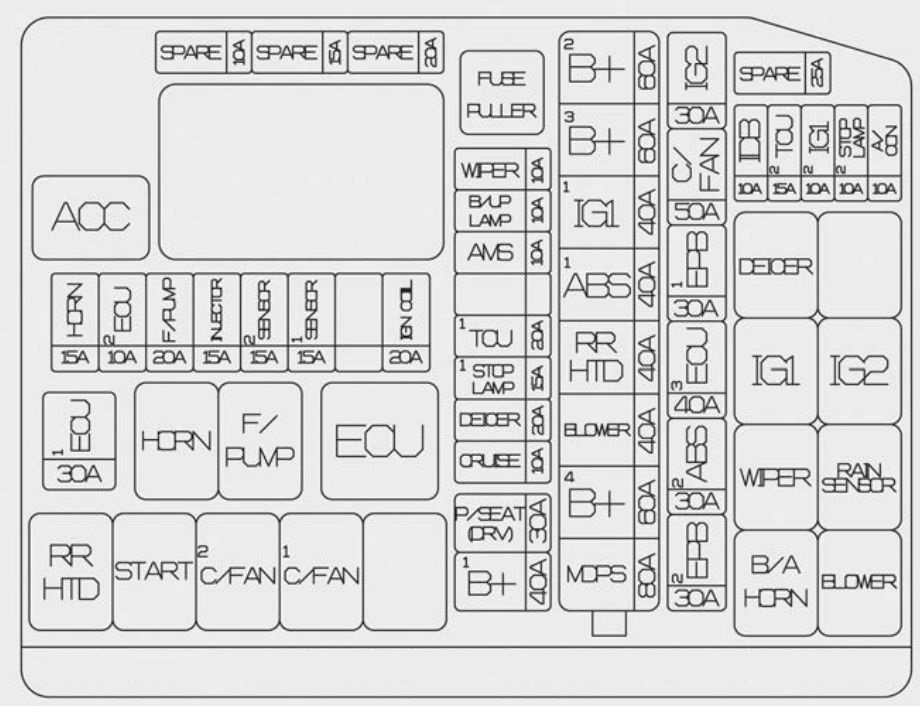
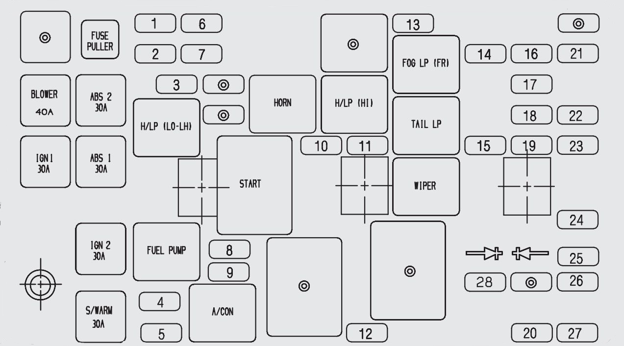
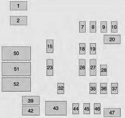
Engine compartment main fuse panel (for petrol engine)
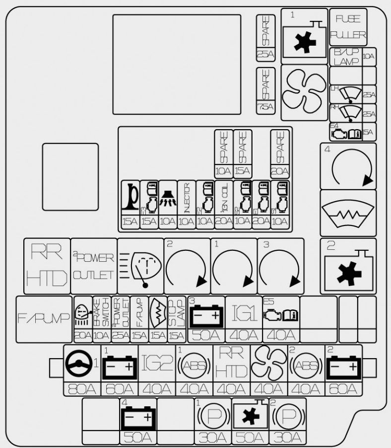
| Fuse | Fuse rating | Symbol | Fuse name | Protected component |
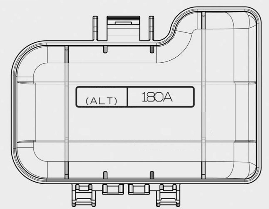
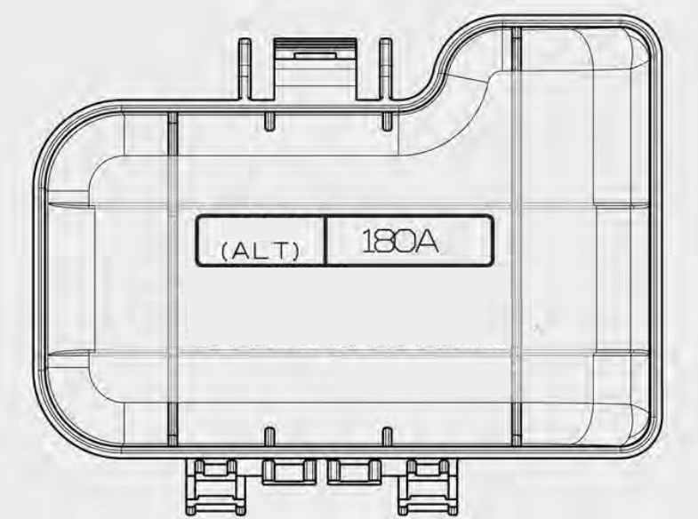
| MULTI FUSE | 80 |  |
MDPS | MDPS Unit |
| 60 |  |
IP_B+1 | Inner Fuse Panel, S/Heater RR, Smart Key 1, 2, P/WDW LH/RH, IPS-1/Arisu-1 (H/Lamp Low RH, H/Lamp Hi RH, Turn FR/RR), IPS-2 (Int Tail Lamp), IPS-4 (Drl Lamp LH/RH), IPS-3 (Frt Fog Lamp LH/RH) | |
| 40 |  |
ABS_1 | ESC Control Module, ABS Control Module | |
| 40 |  |
ABS_2 | ESC Control Module, ABS Control Module, Multipurpose Check Connector | |
| 40 |  |
IGN_2 | W/O Smart Key : Ignition Switch, START RELAY, Starter Fuse No: 26 With Smart Key : IG2 RELAY, START RELAY, IG2 Fuse No: 11, 12, 18, 20, 35 | |
| 60 |  |
IP_B+2 | Inner Fuse Panel, P/seat DRV, Spare3, Fog Lamp RR, IPS-5/Arisu-2 (H/Lamp Low LH, H/Lamp Hi LH, Turn FL/RL), IPS-6 (EXT Tail Lamp LH/RH), IPS-7 (Static Bending Lamp LH), IPS-8 (Static Bending Lamp RH) | |
| 40 |  |
RR HTD | RR HTD RELAY RR HTD, MIRR HTD | |
| 40 |  |
BLOWER | BLOWER RLY, BLOWER MOTOR | |
| FUSE | 40 |  |
IG1 | W/O Smart Key : Ignition Switch
With Smart Key : IG1 RELAY, ACC RELAY, INNER FUSE PANEL (ACC Fuse No: 6,10 IG1 Fuse No: 8,17,19, 23, 24, 31, 33, 36, 37) |
| 30 |  |
EPB_1 | Electric Parking Brake Module | |
| 30 |  |
EPB_2 | Electric Parking Brake Module | |
| 50 |  |
C/FAN | C/FAN LO RELAY, C/FAN HI RELAY, C/FAN MOTOR | |
| 15 |  |
DEICER | DEICER RELAY | |
| 15 |  |
STOP LAMP | Stop Signal Electronic Relay, SSEM,STOP LAMP | |
| 40 |  |
EMS | EMS Box (FUSE No. – 1/2/3/4/5/6/7/8/9) | |
| 50 |  |
B+3 | Inner Fuse Panel (Leak Current Autocut Device, Fuse No. – 4/7/9/14/16/21/22/27/32/40) | |
| 25 |  |
FRT_WIPER_LH | FRT WIPER LH | |
| 25 |  |
FRT_WIPER_RH | FRT WIPER RH | |
| 10 |  |
B/UP LP | M/T : Back-up Lamp Switch, A/T : Transaxle Range Switch, TCU | |
| 15 | ECU4 | ECU | ||
| 50 |  |
B+4 | FRT WIPER LH/RH , ECU4 | |
| 10 |  |
BRAKE_SWITCH | STOP SIGNAL | |
| 20 |  |
H/LP_WASHER | FRT WIPER LH/RH , ECU4 | |
| 30 |  |
P/OUTLET 2 | P/OUTLET RELAY 2 | |
| 7,5 | |
SPARE | SPARE |
| Symbol | Relay name | Type |
 |
COOLING FAN LOW RELAY | H/C MICRO |
 |
COOLING FAN HIGH RELAY | 3725 |
| |
BLOWER RELAY | H/C MICRO |
| |
REAR DEFOGGER RELAY | H/C MICRO |
 |
B/START (IG1) RELAY | H/C MICRO |
 |
B/START (IG2) RELAY | H/C MICRO |
 |
START RELAY | H/C MICRO |
 |
B/START (ACC) RELAY | H/C MICRO |
|
DEICER RLY | ISO MICRO |
 |
F/PUMP RLY | H/C MICRO |
| |
H/LP WASHER RLY | ISO MICRO |
| |
P/OUTLET2 RLY | ISO MICRO |
| Fuse rating | Symbol | Fuse name | Relay name |
| 15 |  |
B/A HORN | B/ALARM HORN RLY |
| 15 | |
ECU3 | ECU |
| 15 |  |
HORN | Horn |
| 10 | INJECTOR | INJECTOR, ECU, FUEL PUMP RELAY | |
| 10 | ECU2 | ECU | |
| 20 | IGN COIL | Ignition Coil #1/#2/#3/#4, Condenser | |
| 10 | SENSOR2 | E/R Fuse & Relay Box (COOLING LOW RELAY), Oil Control Valve #1/#2 | |
| 20 |  |
ECU1 | ECU |
| 10 |  |
SENSOR1 | Oxygen Sensor (UP/DOWN), Variable Intake Solenoid Valve, Purge Control Solenoid Valve |
| 10 | |
SPARE | SPARE |
| 15 | |
SPARE | SPARE |
| 20 | |
SPARE | SPARE |
Engine compartment main fuse panel (for diesel engine)
| Fuse | Fuse rating | Symbol | Fuse name | Protected component |
| MULTI FUSE | 80 | |
MDPS | MDPS Unit |
| 60 | |
IP_B+1 | Inner Fuse Panel, S/Heater RR, Smart Key 1, 2, P/WDW LH/RH, IPS-1/Arisu-1 (H/Lamp Low RH, H/Lamp Hi RH, Turn FR/RR) IPS-2 (Int Tail Lamp), IPS-4 (Drl Lamp LH/RH), IPS-3 (Frt Fog Lamp LH/RH) | |
| 40 | |
ABS_1 | ESC Control Module, ABS Control Module | |
| 40 | |
ABS_2 | ESC Control Module, ABS Control Module, Multipurpose Check Connector | |
| 40 | |
IGN_2 | W/O Smart Key : Ignition Switch, START RELAY, Starter Fuse No – 26
With Smart Key : IG2 RELAY, START RELAY, IG2 Fuse No – 11/12/18/20/35 |
|
| 60 | |
IP_B+2 | Inner Fuse Panel, P/seat DRV, Spare3, Fog Lamp RR,
IPS-5/Arisu-2 (H/Lamp Low LH, H/Lamp Hi LH, Turn FL/RL), IPS-6 (EXT Tail Lamp LH/RH), IPS-7 (Static Bending Lamp LH), IPS-8 (Static Bending Lamp RH) |
|
| 40 | |
RR HTD | RR HTD RELAY RR HTD, MIRR HTD | |
| 40 | |
BLOWER | BLOWER RLY, BLOWER MOTOR | |
| FUSE | 40 | |
IG1 | W/O Smart Key : Ignition Switch
With Smart Key : IG1 RELAY, ACC RELAY, INNER FUSE PANEL (ACC Fuse No – 6/10 IG1 Fuse No – 8/17/19/23/24/31/33/36/37) |
| 30 | |
EPB_1 | Electric Parking Brake Module | |
| 30 | |
EPB_2 | Electric Parking Brake Module | |
| 50 | |
C/FAN | C/FAN LO RELAY, C/FAN HI RELAY, C/FAN MOTOR | |
| 15 | |
DEICER | DEICER RELAY | |
| 15 | |
STOP LAMP | Stop Signal Electronic Relay, SSEM,STOP LAMP | |
| 20 |  |
TCU1 | TCU | |
| 30 |  |
FUEL HEATER | FUEL HEATER RELAY | |
| 40 | |
EMS | EMS Box (FUSE No. – 1/2/3/4/5/6/7/8/9) | |
| 50 | |
B+3 | Inner Fuse Panel (Leak Current Autocut Device, Fuse No. – 4/7/9/14/16/21/22/27/32/40) | |
| 25 | |
FRT_WIPER_LH | FRT WIPER LH | |
| 25 | |
FRT_WIPER_RH | FRT WIPER RH | |
| 10 | |
B/UP LP | M/T : Back-up Lamp Switch, A/T : Transaxle Range Switch, TCU | |
| 50 | |
B+4 | FRT WIPER LH/RH , ECU4 | |
| 10 | |
BRAKE_SWITCH | STOP SIGNAL | |
| 20 | |
H/LP_WASHER | FRT WIPER LH/RH , ECU4 | |
| 25 | |
P/OUTLET 2 | P/OUTLET RELAY 2 | |
| 7,5 | |
SPARE | SPARE | |
| 7,5 | |
SPARE | SPARE |
| Symbol | Relay name | Type |
|
COOLING FAN LOW RELAY | H/C MICRO |
|
COOLING FAN HIGH RELAY | 3725 |
|
BLOWER RELAY | H/C MICRO |
|
REAR DEFOGGER RELAY | H/C MICRO |
|
B/START (IG2) RELAY | H/C MICRO |
| |
B/START (IG1) RELAY | H/C MICRO |
|
START RELAY | H/C MICRO |
|
B/START (ACC) RELAY | H/C MICRO |
|
FUEL HEATER RELAY | H/C MICRO |
|
DEICER | ISO MICRO |
|
H/LP WASHER RLY | ISO MICRO |
|
P/OUTLET2 RLY | ISO MICRO |
| Fuse rating | Symbol | Fuse name | Relay name |
| 15 | |
SPARE | SPARE |
| 15 | |
HORN | HORN RELAY |
| 20 | |
SPARE | SPARE |
| 10 |  |
SENSOR2 | E/R Fuse & Relay Box (COOLING FAN LOW RELAY), Lambda Sensor (D4FB), Stop Lamp Switch |
| 20 | |
ECU1 | ECU |
| 10 | |
SENSOR1 | DSL Box (PTC1 RELAY, GLOW RELAY), VGT Control Sensor, Camshaft Position Sensor, Electrical EGR Valve |
| 15 | |
B/A_HORN | B/ALARM HORN RLY |
| 20 | |
SPARE | SPARE |
Engine compartment fuse panel (Diesel engine only)
| Symbol | Fuse rating/ RELAY name | Fuse name |
 |
GLOW RLY | GLOW RLY |
 |
PTC_HTR_1 RLY | PTC_HTR_1 RLY |
 |
PTC_HTR_2 RLY | PTC_HTR_1 RLY |
 |
PTC_HTR_3 RLY | PTC_HTR_3 RLY |
|
80 | GLOW |
|
50 | PTC_HTR_1 |
|
50 | PTC_HTR_2 |
| |
50 | PTC_HTR_3 |
WARNING: Terminal and harness assignments for individual connectors will vary depending on vehicle equipment level, model, and market.