KIA Amanti (2003 – 2005) – fuse box diagram
Year of production: 2003, 2004, 2005
Also called:
- KIA Opirus
- KIA Iris
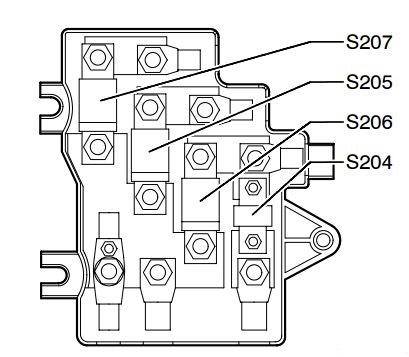
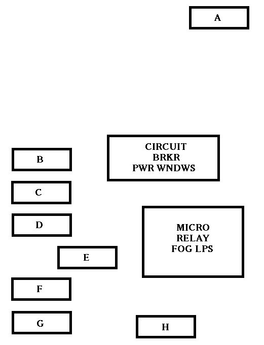
Relay panel description
Passenger side panel
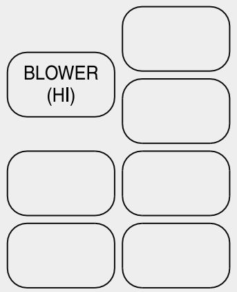
| Relay name | Relay description |
| BLOWER (HI) | Air conditioner blower relay (high) |
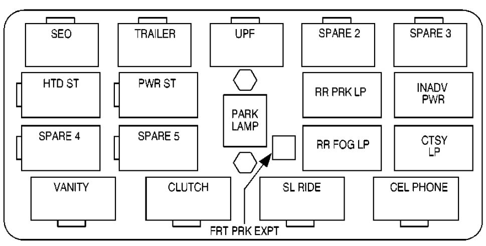
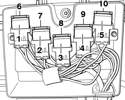
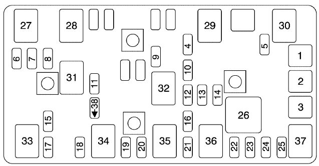
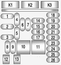
Engine compartment
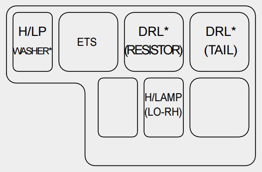
| Relay name | Relay description |
| H/LP WASHER | Head lamp washer relay |
| ETS | Electronic throttle system relay |
| DRL (RESISTOR)* | Daytime running light (Resistor) relay |
| DRL (TAIL)* | Daytime running light (Taillight) relay |
| H/LAMP (LO-RH) | Headlight relay (low beam-right) |
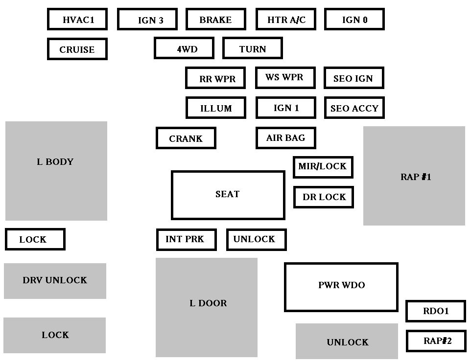
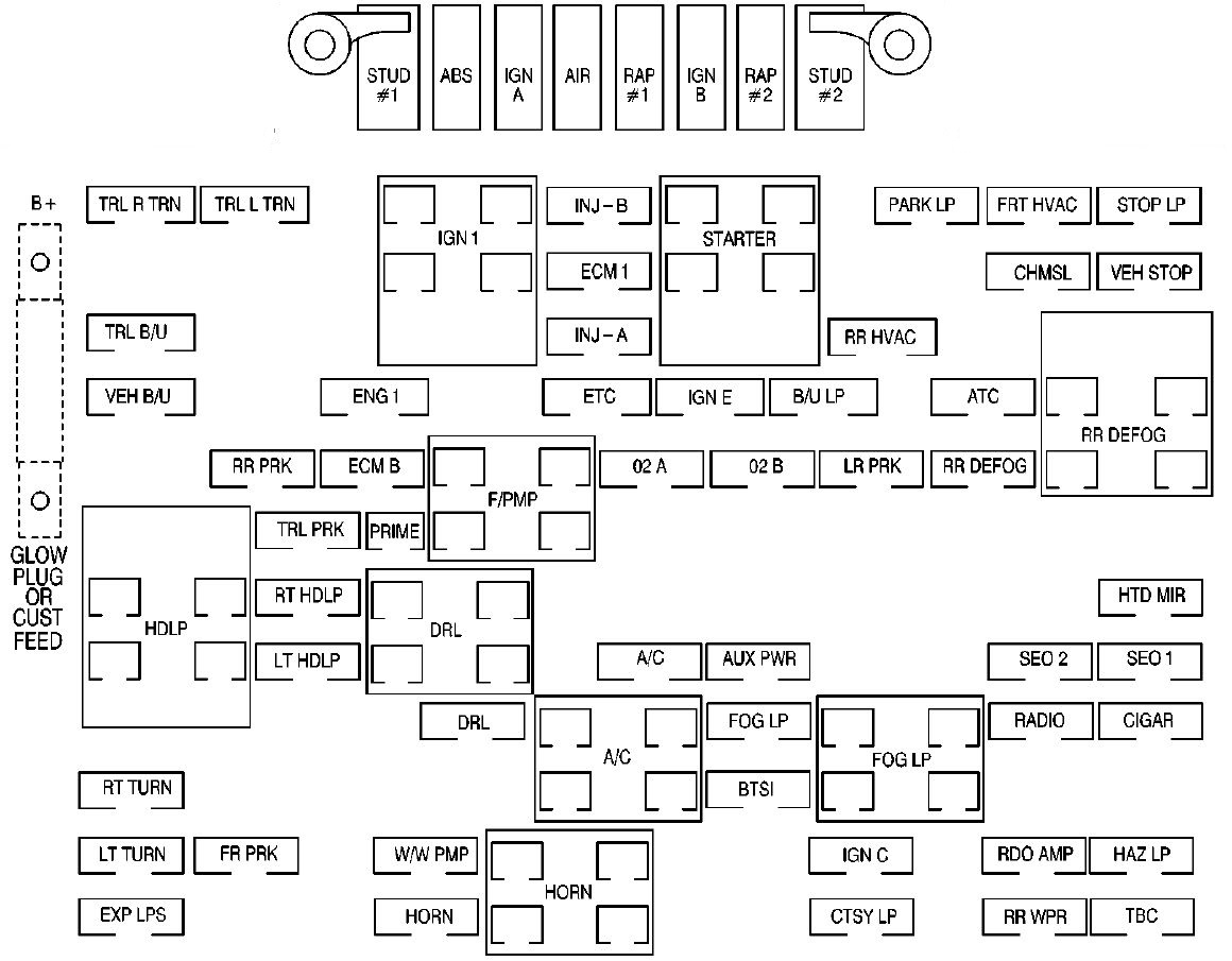
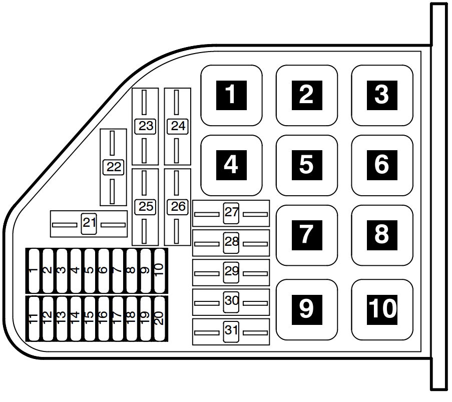
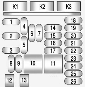
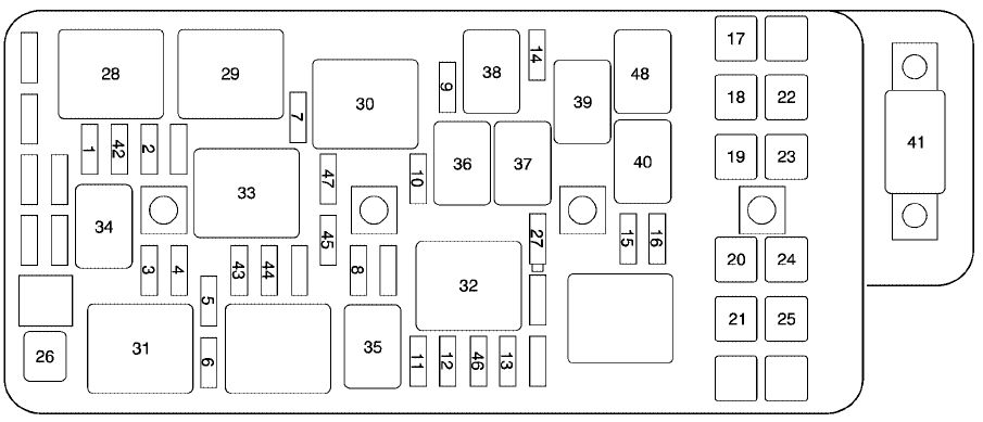
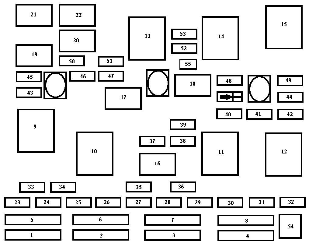
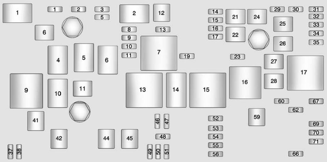
Fuse/Relay panel description
Engine compartment
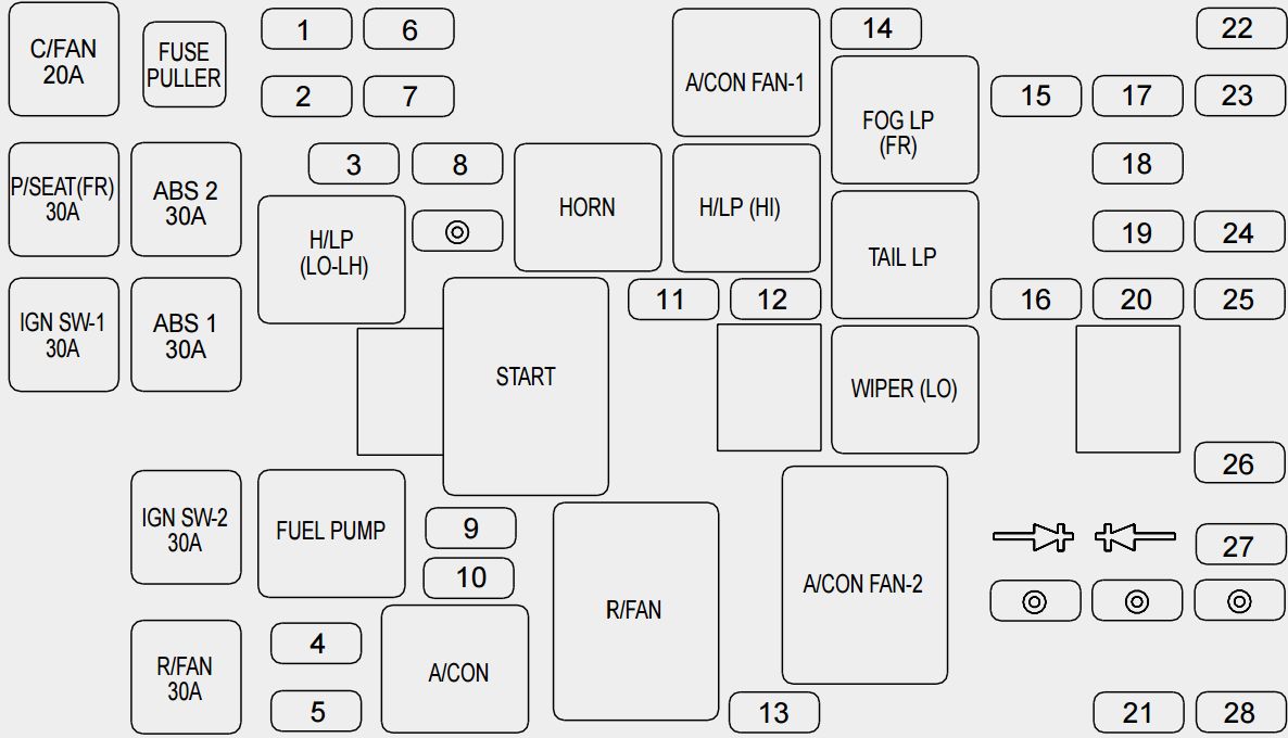
| Description | Fuse rating | Protected component | |
| 1 | FUEL PUMP | 20 | Fuel pump |
| 2 | H/LP (LO-LH) | 15 | Headlight (low-left) |
| 3 | ABS | 10 | Anti-lock brake system |
| 4 | INJECTOR | 10 | Injector |
| 5 | A/CON COMP | 10 | Air-conditioner compressor |
| 6 | ATM RLY | 20 | Automatic transaxle control relay |
| 7 | ECU RLY | 20 | Engine control unit relay |
| 8 | IGN COIL | 20 | Ignition coil |
| 9 | O2 SNSR | 15 | Oxygen sensor |
| 10 | ENG SNSR | 15 | Power train control system sensors |
| 11 | HORN | 15 | Horn |
| 12 | TAIL LP | 20 | Tail light |
| 13 | H/LP WASHER | 20 | Headlight washer |
| 14 | ETS | 20 | Electronic throttle system |
| 15 | FOG LP (FR) | 15 | Fog light (front) |
| 16 | H/LP (HI) | 15 | Headlight (high) |
| 17 | SPARE | 30 | spare fuse |
| 18 | SPARE | 20 | spare fuse |
| 19 | SPARE | 15 | spare fuse |
| 20 | SPARE | 10 | spare fuse |
| 21 | BLOWER MTR | 30 | Blower motor |
| 22 | S/WARMER | 30 | Seat warmer |
| 23 | AMP | 20 | Radio amplifier |
| 24 | DRL* | 15 | Daytime running light |
| 25 | H/LP (LO-RH) | 15 | Headlight (low beam-right) |
| 26 | P/FUSE-1 | 30 | All electrical system |
| 27 | ECU | 10 | Engine control unit |
| 28 | ECS | 15 | Electronic control suspension |
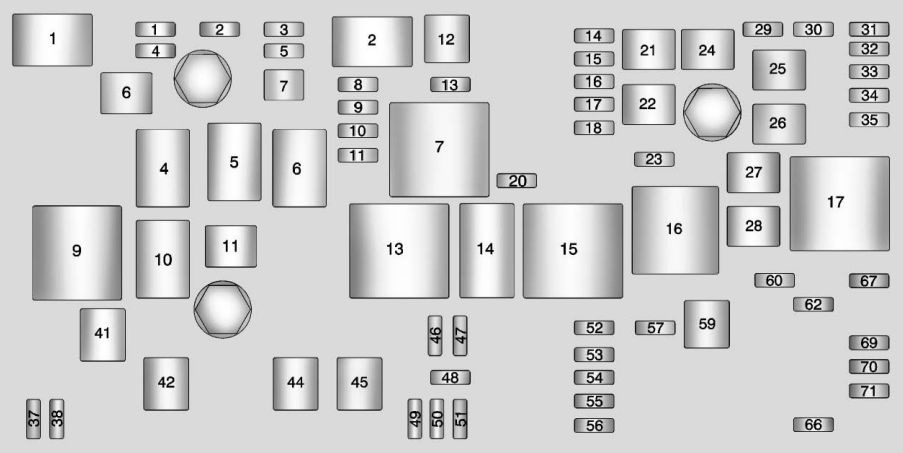
| NOT USED | Not used | ||
| C/FAN | 20 | Condenser fan | |
| P/SEAT (FR) | 30 | Power seat (front) | |
| IGN SW-1 | 30 | Ignition switch | |
| ABS 2 | 30 | Anti-lock brake system | |
| ABS 1 | 30 | Anti-lock brake system | |
| IGN SW-2 | 30 | Ignition switch | |
| R/FAN | 30 | Radiator fan | |
| H/LP (LO-LH) | Headlight relay (low beam-left) | ||
| FUEL PUMP | Fuel pump relay | ||
| HORN | Horn relay | ||
| START | Start motor relay | ||
| A/CON | Air conditioner relay | ||
| A/CON FAN-1 | Air conditioner fan relay | ||
| H/LP (HI) | Headlight relay (high beam) | ||
| R/FAN | Radiator fan relay | ||
| FOG LP (FR) | Fog light relay (front) | ||
| TAIL LP | Taillight relay | ||
| WIPER (LO) | Wiper relay (low) | ||
| A/CON FAN-2 | Air conditioner fan relay | ||
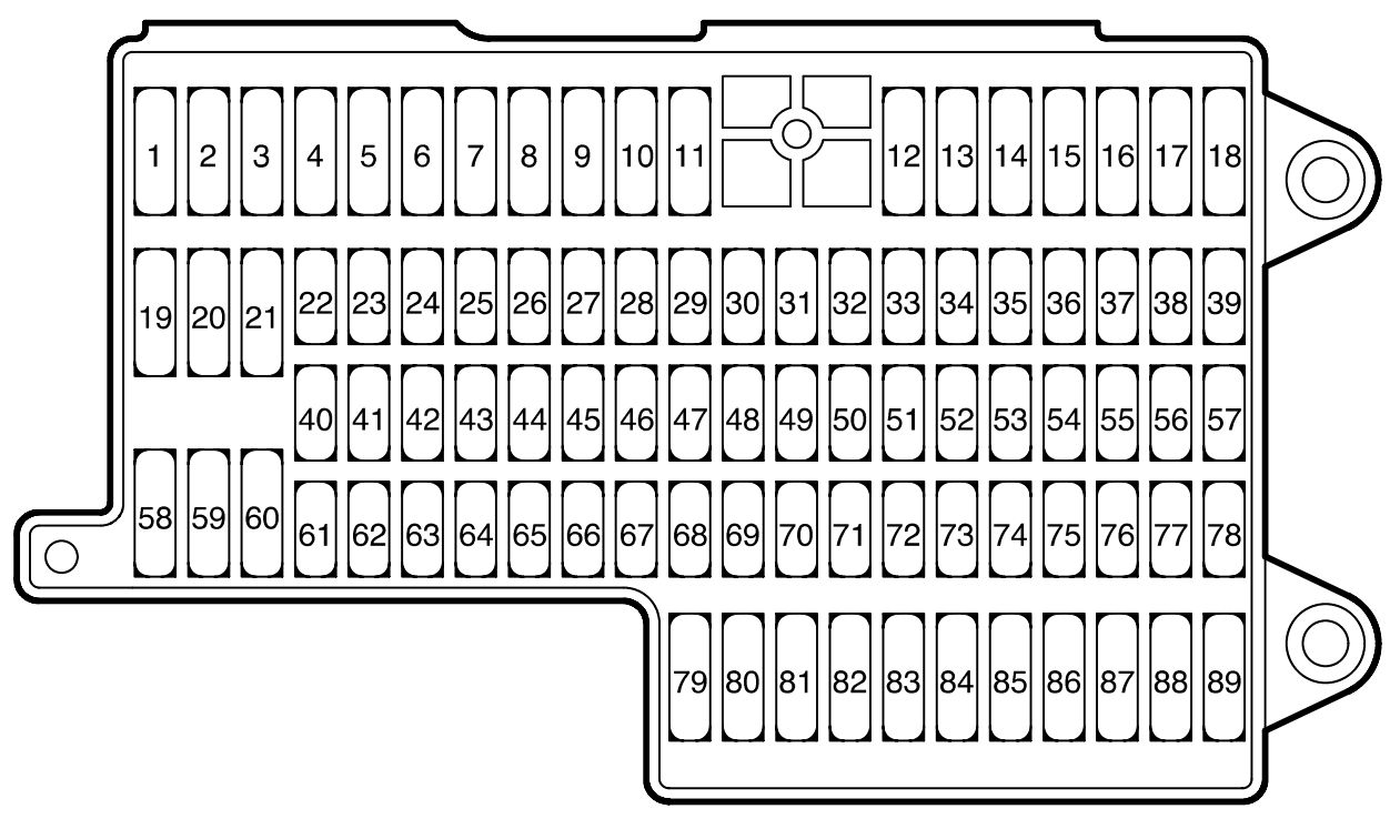
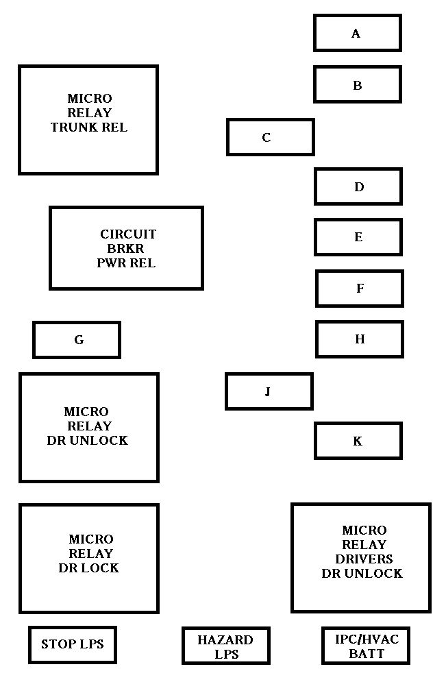
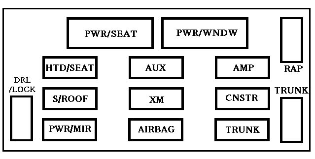
Driver-side knee bolster
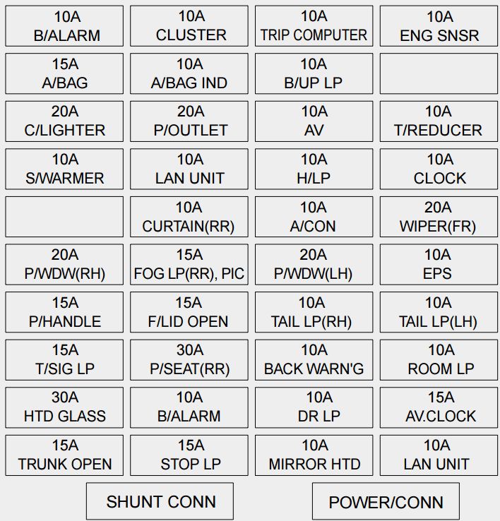
| Description | Fuse rating | Protected component |
| B/ALARM | 10 | Burglar alarm |
| A/BAG | 15 | Airbag |
| C/LIGHTER | 20 | Cigar lighter |
| S/WARMER | 10 | Seat warmer |
| P/WDW(RH) | 20 | Power window (right) |
| P/HANDLE | 15 | Power steering wheel |
| T/SIG LP | 15 | Turn signal light |
| HTD GLASS | 30 | Defroster |
| TRUNK OPEN | 15 | Trunk lid opener |
| CLUSTER | 10 | Cluster |
| A/BAG IND | 10 | Airbag indicator |
| P/OUTLET | 20 | Electrical power socket |
| LAN UNIT | 10 | Lan unit |
| CURTAIN(RR) | 10 | Electric curtain (rear) |
| FOG LP(RR), PIC | 15 | Fog light (rear), Personal identification card |
| F/LID OPEN | 15 | Fuel filler lid opener |
| P/SEAT(RR) | 30 | Power seat (rear) |
| B/ALARM | 10 | Burglar alarm |
| STOP LP | 15 | Stop light |
| TRIP COMPUTER | 10 | Trip computer |
| B/UP LP | 10 | Back-up light |
| AV | 10 | Audio |
| H/LP | 10 | Headlight |
| A/CON | 10 | Air-conditioning system |
| P/WDW(LH) | 20 | Power window (left) |
| TAIL LP(RH) | 10 | Taillight (right) |
| BACK WARN’G | 10 | Back warning |
| DR LP | 10 | Door courtesy lamp |
| MIRROR HTD | 10 | Outside review mirror defroster |
| ENG SNSR | 10 | Power train control system sensors |
| T/REDUCER | 10 | Seat belt tension reducer |
| CLOCK | 10 | Clock |
| WIPER(FR) | 20 | Wiper (front) |
| EPS | 10 | Electronic power steering |
| TAIL LP(LH) | 10 | Tail light (left) |
| ROOM LP | 10 | Room lamp |
| AV, CLOCK | 15 | Audio, Clock |
| LAN UNIT | 10 | Lan unit |
| SHUNT CONN | — | Switch illumination |
| POWER/CONN | — | Power connector |
WARNING: Terminal and harness assignments for individual connectors will vary depending on vehicle equipment level, model, and market.