RAM 1500 (2009) – fuse box diagram

RAM 1500 (2009) – fuse box diagram

Year of production: 2009

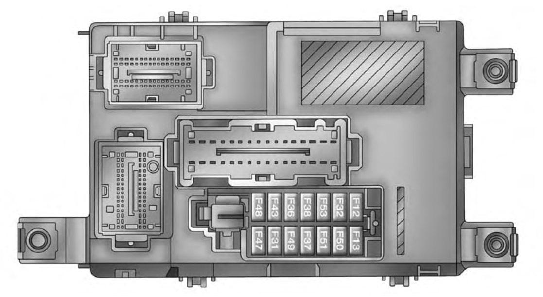
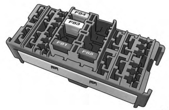
Totally Integrated Power Module (TIPM)

The totally integrated power module (TIPM) is located in the engine compartment near the battery.

Cavity Cartridge fuse Micro Fuse Description
J01 30 Bat – Presafe #1
J02 30 Bat – Trailer Tow Main
J03 25 Bat – Passenger Door Node
J04 40 Bat – ABS Pump
J05 30 Bat – ABS Valve
J06 30 Bat – H/Lamp Wash/MTV/CM2200/Elec Vac Pump
J07 25 Bat – Driver Door Node
J08 30 Bat – DTCM/Axle Locks
J09 30 Bat – Plg/Electric Brake
J10 40 Bat – L/Bar/Off-Road
J11 30 Bat – Sway/Thatchum/Rear Doors
J12 40 Starter Solenoid
J13 60 Bat – Rad Fan #1/#2/SSR
J14 40 Bat – Folding Seat/PZEV
J15 60 Bat – IOD Main
J16 40 Frt HVAC Motor
M17 25 Bat – Sunroof/Skylight
M18 25 TCM/Trans Range
M19 5 Ign R/ACC – Sunroof/Window Sw Illum
M20 25 Frt Wiper
M21 25 Door Locks
M22 20 Fuel Pump
M23 20 Bat – Trlr Light/Pre-Safe #2
M24 20 Bat – Trlr Tow BUX/HGM
M25 10 Bat – J1962 Diag/Mirrors
M26 10 Bat – Ign Sw, WIN, PASS
M27 15 Bat – CHMSL/Brake Sw
M28 10 Bat – Corax TPM/PEM/HVAC Htr Pump
M29 15 Bat – Folding Mirror
M30 25 Bat – Inverter
M31 20 Bat – Pwr Out #1
M32 20 Fr/Rr Washer
M33 15 Bat – NGC/EATX/PCM
M34 15 Bat – CCN/Interior Light/SCM/Sw Bank
M35 20 Ign R-Frt Seat/Vent
M36 20 Ign R-Rear Seat/Steer Wheel
M37 10 Horn #1
M38 20 IOD-CCN/Interior Mods
M39 30 IOD-Amp/Radio
M40 25 Rear Wiper
M41 15 IOD-SDARS/VES2–3/DVD/HFM/UGDO/Vanity Lamp
M42 10 IOD-HVAC, U/Hood Lamp
M43 10 Horn #2
M44 10 IGN R/S-ORC/OCM
M45 10 IGN R-ORC/Trail Tow (BUX) Sense
M46 20 IGN R-Trail Tow (BUX)
M47 10 IGN R-H/Lamp Wash/HVAC/Park Assist/Ir Sns
M48 20 IGN R/ACC-Pwr Outlet #2
M49 20 IGN R/ACC/Bat-Pwr Outlet #3
M50 25 ASD #1, #2
M51 20 ASD #3
M52 10 IGN R/S-SWAY/TCASE/DTCM/FAD
M53 15 IGN R/S-MFSW/CNN/SCM/TPM/RR View
M54 20 IOD – Spare

WARNING: Terminal and harness assignments for individual connectors will vary depending on vehicle equipment level, model, and market.

RAM ProMaster City (2017) – fuse box diagram

RAM ProMaster City (2017) – fuse box diagram

Year of production: 2017

Underhood Fuses

The Front Power Distribution Center is located on the driver’s side of the engine compartment.

Cavity Maxi fuse Mini fuse Description
F01 60 Body Controller
F02 40 Rear Power Windows, Fog Lamps, Front Heated Seats (If Equipped)
30 Rear Power Windows, Front Heated Seats (If Equipped)
30 Fog Lamps, Front Heated Seats (If Equipped)
20 Front Heated Seats
F03 20 Ignition Switch
F04 40 BSM System Module
F06 20 Radiator Fan – Low Speed
F07 50 Radiator Fan – High Speed
F08 40 Blower Motor
F10  — 10 Horn
F11 10 Secondary Loads ECM
F14 15 High Beam
F16  — 5 ECM and Transmission Shifter
F17 25 ECM Power Loads
F18  — 5 ECM Load, Main Relay
F19 7,5 Air Conditioning
F20 30 Rear Defroster
F21 5 Key Unlock
F22 10 Primary ECM Loads
F23 20 BSM System
F24 5 BSM System, Positive Key and Steering Angle Sensor
F30 15 Fog Lamp
F83  20 Fuel Pump
F84  — 15 AT Module
F85 15 Rear Power Outlet 12V
F86 15 IP Power Outlet 12V
F87 5 IBS
F88 7,5 External Mirror Defrost

Interior Fuses

The interior fuse panel is part of the Body Control Module (BCM) and is located on the driver’s side under the instrument panel.

RAM ProMaster City – fuse box – interior
Cavity Mini fuse Description
F53 5 KL 30 (+30) – IPC
F38 20 Central Doors Locking
F36 10 KL 30 (+30) – TPMS, EOBD, HVAC, Radio
F43 15 Bi-Directional Washer Pump
F48 20 Passenger Power Windows
F50 7,5 KL 15 (+15) – Air-Bag
F51 7,5 KL 15 (+15) – External Mirror Adjustment Command, HVAC, RVC, HWB Coils
F37 5 KL 15 (+15) – Brake Pedal Switch (N.O.), IPC, Brake Pedal Switch (N.C.)
F49 5 KL 15 (+15) – PAM, CSS Lighting, ECM Backlighting, TTM
F31 5 KL 15a (INT A) – HWB, MCO
F47 20 Driver Power Windows

Central Unit Fuse Panel

The central power fuse panel is located on the driver’s side under the instrument panel.

RAM ProMaster City – fuse box – central unit
Cavity Mini fuse Description
F1 10 Front Heated Seat Driver
F2 10 Front Heated Seat Passenger
F3 20 Rear Power Window Driver side
F4 20 Rear Power Window Passenger side
F5 15 2nd Instrument Panel Power Outlet 12V

WARNING: Terminal and harness assignments for individual connectors will vary depending on vehicle equipment level, model, and market.

RAM ProMaster City (2016) – fuse box diagram

RAM ProMaster City (2016) – fuse box diagram

Year of production: 2016

Underhood Fuses

The Front Power Distribution Center is located on the driver’s side of the engine compartment.

Cavity Maxi fuse Mini fuse Description
F01 60 Body Controller
F02 40 Front Heated Seats, Second 12 Volt IP Outlet
60 Rear Power Window Including Front Heated Seats, Second 12 Volt IP Outlet
F03 20 Ignition Switch
F04 40 BSM System Module
F05 50 Available
F06 30 Radiator Fan – Low Speed
F07 40 Radiator Fan – High Speed
F08 40 Blower Motor
F10  — 10 Horn
F11 10 Secondary Loads ECM
F14 15 High Beam
F16  — 5 ECM and Transmission Shifter
F17 25 ECM Power Loads
F18  — 5 ECM Load, Main Relay
F19 7,5 Air Conditioning
F20 30 Rear Defroster
F21 5 Key Unlock
F22 10 Primary ECM Loads
F23 20 BSM System
F24 5 BSM System, Positive Key and Steering Angle Sensor
F30 15 Fog Lamp
F83  20 Fuel Pump
F84  — 15 AT Module
F85 15 Rear Power Outlet 12V
F86 15 IP Power Outlet 12V
F87 5 IBS
F88 7,5 External Mirror Defrost

Interior Fuses

The interior fuse panel is part of the Body Control Module (BCM) and is located on the driver’s side under the instrument panel.

RAM ProMaster City – fuse box – interior
Cavity Mini fuse Description
F53 5 KL 30 (+30) – IPC
F38 20 Central Doors Locking
F36 10 KL 30 (+30) – TPMS, EOBD, HVAC, Radio
F43 15 Bi-Directional Washer Pump
F48 20 Passenger Power Windows
F50 7,5 KL 15 (+15) – Air-Bag
F51 7,5 KL 15 (+15) – External Mirror Adjustment Command, HVAC, RVC, HWB Coils
F37 5 KL 15 (+15) – Brake Pedal Switch (N.O.), IPC, Brake Pedal Switch (N.C.)
F49 5 KL 15 (+15) – PAM, CSS Lighting, ECM Backlighting, TTM
F31 5 KL 15a (INT A) – HWB, MCO
F47 20 Driver Power Windows

Central Unit Fuse Panel

The central power fuse panel is located on the driver’s side under the instrument panel.

RAM ProMaster City – fuse box – central unit
Cavity Mini fuse Description
F1 10 Front Heated Seat Driver
F2 10 Front Heated Seat Passenger
F3 20 Rear Power Window Driver side
F4 20 Rear Power Window Passenger side
F5 15 2nd Instrument Panel Power Outlet 12V

WARNING: Terminal and harness assignments for individual connectors will vary depending on vehicle equipment level, model, and market.

RAM ProMaster City (2015) – fuse box diagram

RAM ProMaster City (2015) – fuse box diagram

Year of production: 2015

Underhood Fuses

The Front Power Distribution Center is located on the driver’s side of the engine compartment.

Cavity Maxi fuse Mini fuse Description
F01 60 Body Controller
F02 40 Front Heated Seats, Second 12 Volt IP Outlet
60 Rear Power Window Including Front Heated Seats, Second 12 Volt IP Outlet
F03 20 Ignition Switch
F04 40 BSM System Module
F05 50 Available
F06 30 Radiator Fan – Low Speed
F07 40 Radiator Fan – High Speed
F08 40 Blower Motor
F09 10 Available
F10 15 Horn
F11 10 Secondary Loads ECM
F14 15 High Beam
F15 15 Available
F16 5 ECM and Transmission Shifter
F17 25 ECM Power Loads
F18 5 ECM Load, Main Relay
F19 7,5 Air Conditioning
F20 30 Rear Defroster
F21 5 Key Unlock
F22 10 Primary ECM Loads
F23 20 BSM System
F24 5 BSM System, Positive Key and Steering Angle Sensor
F30 15 Fog Lamp
F81 Available
F82 Available
F83 Fuel Pump
F84 15 AT Module
F85 15 Rear Power Outlet 12V
F86 15 IP Power Outlet 12V
F87 5 IBS
F88 7,5 External Mirror Defrost

Interior Fuses

The interior fuse panel is part of the Body Control Module (BCM) and is located on the driver’s side under the instrument panel.

RAM ProMaster City – fuse box – interior
Cavity Mini fuse Description
F53 5 KL 30 (+30) – IPC
F38 20 Central Doors Locking
F36 10 KL 30 (+30) – TPMS, EOBD, HVAC, Radio
F43 15 Bi-Directional Washer Pump
F48 20 Passenger Power Windows
F50 7,5 KL 15 (+15) – Air-Bag
F51 7,5 KL 15 (+15) – External Mirror Adjustment Command, HVAC, RVC, HWB Coils
F37 5 KL 15 (+15) – Brake Pedal Switch (N.O.), IPC, Brake Pedal Switch (N.C.)
F49 5 KL 15 (+15) – PAM, CSS Lighting, ECM Backlighting, TTM
F31 5 KL 15a (INT A) – HWB, MCO
F47 20 Driver Power Windows

Central Unit Fuse Panel

The central power fuse panel is located on the driver’s side under the instrument panel.

RAM ProMaster City – fuse box – central unit
Cavity Mini fuse Description
F1 10 Front Heated Seat Driver
F2 10 Front Heated Seat Passenger
F3 20 Rear Power Window Driver side
F4 20 Rear Power Window Passenger side
F5 15 2nd Instrument Panel Power Outlet 12V

WARNING: Terminal and harness assignments for individual connectors will vary depending on vehicle equipment level, model, and market.

RAM ProMaster (2014) – fuse box diagram

RAM ProMaster (2014) – fuse box diagram

Year of production: 2014

Underhood Fuses

The Front Power Distribution Center is located on the driver’s side of the engine compartment.

Cavity Maxi fuse Mini fuse Description
F01 40 ESC Pump
F02 20 (3.6 Gasoline Engine) Starter Relay 3.6L (3.6 Gasoline Engine)
50 (3.0 Diesel
Engine)
Glow Plug Unit (3.0 Diesel Engine)
F04 50 (3.6 Gasoline Engine) Secondary PDC (Trans Power Relay, Vacuum Pump, KL30 for STM) (3.6 Gasoline Engine)
40 (3.0 Diesel Engine) Fuel Filter Heater (3.0 Diesel Engine)
F05 30 SELESPEED Pump RELE (3.0 Diesel Engine) – If Equipped
F06 40 (non A/C) Engine Cooling Fan – 2nd Speed
60 (A/C)
F07 50 (non A/C) Engine Cooling Fan – 1st Speed
60 (A/C)
F08 40 Passenger Compartment Blower
F09 15 Rear Power Outlet
F10 15 Horn
F11 15 MPROP-DRV (3.0 Diesel Engine) — If Equipped
F14 20 Power Outlet
F15 7,5 USB Charger
F16 7,5 KL15 STM (3.6), KL15 Starter Relay Coil (3.6 Gasoline Engine) KL15 MTA, KL15 Shift Lever Unit, KL15 ECM, KL15 Starter Relay Coil (3.0 Diesel Engine)
F17 20 ECM, Injectors (3.6 Gasoline Engine)
Secondary Loads, ECM (3.0 Diesel Engine)
F18 7,5 KL30 ECM, KL30 Main Relay Coil (3.6 Gasoline Engine)
7,5 KL30 MTA, KL30 ECM, KL30 Main Relay Coil (3.0 Diesel Engine)
F19 7,5 A/C Compressor (If Equipped)
F20 30 Windshield Wiper
F21 15 Fuel Pump
F22 20 ECM, Ignition Coils (3.6 Gasoline Engine)
20 ECM, Primary Loads (3.0 Diesel Engine)
F23 20 ESC Valves
F24 7,5 KL15 Vacuum pump relay coil (3.6 Gasoline Engine) — If Equipped
F30 15 Heated Mirrors


Front PDC Additional Fuses

The additional fuse box is located inside the front PDC Box.

RAM ProMaster – fuse box – front power distribution center
Cavity Mini fuse Description
F61 20 Vacuum Pump (3.6 Gasoline Engine) — If Equipped
F62 30 Transmission Power RELE (3.6 Gasoline Engine) — If Equipped
F64 7,5 Urea Pump (3.0 Diesel Engine) — If Equipped
F65 25 Urea NOX Sensor 1–2 — PM Sensor (3.0 Diesel Engine) — If Equipped
F66 5 STM (3.6 Gasoline Engine) — If Equipped


Interior Fuses

The interior fuse panel is part of the Body Control Module (BCM) and is located on the driver’s side under the instrument panel.

RAM ProMaster – fuse box-interior fuse panel
Cavity Mini fuse Description
F12 10 Right Low Beam
F13 10 Left Low Beam
F31 5 INT/A
F32 10 SBMT
F34 7,5 Clearance Lights
F36 15 +30 (ACM – TPCU – RRM – DLC)
F37 5 INT (BRAKE NO – IPC)
F38 15 Central Locking
F42 5 INT (BSM – SAS – BRAKE NC)
F43 20 Bi-Directional Washer Pump
F47 20 Driver Power Window
F48 20 Passenger Power Window
F49 5 INT (PAM – CCS – RRM – ECM)
F50 7,5 INT (ORC)
F51 5 INT (REAR CAMERAAUX)
F53 5 +30 (IPC)
F90 7,5 Left High Beam
F91 7,5 Right High Beam
F92 7,5 Left Fog Lamp
F93 7,5 Right Fog Lamp

Right Central Pillar Fuses

The right central pillar fuse panel is located on the interior side at the base of the passenger side B pillar.

RAM ProMaster – fuse box – rear fuse panel
Cavity Mini fuse Description
F81 7,5 Seat Heater
F83 20 Rear Left Windows Heater
F84 20 Rear Right Windows Heater
F85 10 Rear Heater Prep

WARNING: Terminal and harness assignments for individual connectors will vary depending on vehicle equipment level, model, and market.

RAM Dakota (2010) – fuse box diagram

RAM Dakota (2010) – fuse box diagram

Year of production: 2010

Power Distribution Center

Power distribution center located on the left side of the engine compartment.

Cavity Cartridge fuse Micro Fuse Description
1 Spare
2 Spare
3 30 Electric Brake
4 50 Power Seat
5 Spare
6 20 Ignition Off Draw (IOD) Cabin Compartment Node (CCN), Radio
7 10 Powertrain Control Module (PCM)/Fuel/RAD/AC Coils
8 10 Cabin Compartment Node (CCN)/Mirror/4×4
9 Spare
10 2 Run/Start Ignition Switch
11 10 AC Clutch
12 15 Trailer Tow Lt Stop/Turn
13 15 Trailer Tow Rt Stop/Turn
14 20 Ignition Off Draw (IOD) #2
15 25 Trans/Powertrain Control Module (PCM)
16 20 Horn
17 20 ABS Feed (Valves)
18 20 Fuel Pump
19 15 Center High-Mounted Stop Light (CHMSL)
20 20 Cabin Compartment Node (CCN) Door Locks/Brake Transmission Shift Interlock (BTSI)
21 25 Audio Amp
22 20 Power Outlet (Switchable)
23 20 Fog Lamps
24 20 Powertrain Control Module (PCM) B+
25 15 Cabin Compartment Node (CCN) Illumination
26 20 Ignition Run/Start Feed
27 10 Power Mirror
28 20 Power Outlet
29 20 Front Control Module (FCM) 4 (Wipers)
30 Spare
31 30 Ignition Run/AC/ Windows
32 30 Front Control Module (FCM) 1 (Ext. Lights #1)
33 30 Auto Shut Down (ASD)
34 30 Front Control Module (FCM) 2 (Ext. Light #2)
35 40 HVAC Blower Motor
36 Spare
37 Spare
38 20 Spare
39 30 Starter Solenoid
40 40 Ignition Run Feeds
41 30 Wiper Motor
42 25 Front Control Module (FCM) 5 (T-Case)
43 10 Lt Park Lamps
44 10 Rt Park Lamps
45 20 Trailer Tow Park Lamps
46 10 Airbag System # 2
47 Spare
48 20 Sunroof/Sound Box
49 30 Trailer Tow B+
50 40 Anti-Lock Brake System (ABS) Module (Pump)
51 40 Park Lamps
52 Spare
53 40 Rear Defogger
54 Spare
55 Spare
56 10 Heated Seats
57 20 Airbag System # 2
58 20 Heated Seats
59 10 HVAC Module
60 10 ABS Module
61 20 Front Control Module (FCM) 3 (Reverse Lamps)

WARNING: Terminal and harness assignments for individual connectors will vary depending on vehicle equipment level, model, and market.

RAM Cargo Van (2014 – 2015) – fuse box diagram

RAM Cargo Van (2014 – 2015) – fuse box diagram

Year of production: 2014, 2015

Totally Integrated Power Module

The Totally Integrated Power Module is located in the engine compartment near the battery

Cavity Cartridge fuse Micro Fuse Description
J1 40 Power Folding Seat
J2 30 Power Liftgate Module
J3 30 Rear Door Module
J4 25 Driver Door Node
J5 25 Passenger Door Node
J6 40 Antilock Brakes Pump/Stability Control System
J7 30 Antilock Brakes Valve/Stability Control System
J8 40 Power Memory Seat – If Equipped
J9 40 Partial Zero Emissions Vehicle Motor/Flex Fuel – If Equipped
J10 30 Headlamp Wash/Manifold Tuning Valve – If Equipped
J11 30 Power Sliding Door Module/Anti–Theft Module – If Equipped
J12 30 HVAC Rear Blower, Radiator Fan Motor
J13 60 Ignition Off Draw (IOD) – Main
J14 40 Rear Window Defogger
J15 40 Front Blower
J17 40 Starter Solenoid
J18 20 Powertrain Control Module Trans Range
J19 60 Radiator Fan
J20 30 Front Wiper LO/HI
J21 20 Front/Rear Washer
J22 25 Sunroof Module
M1 15 Rear Center Brake Lamp/Brake Switch
M2 20 Front Fog Lamps
M3 20 Front/Rear Axle Locker, Vacuum Pump Motor
M4 10 Trailer Tow
M5 25 Inverter
M6 20 Power Outlet #1 (ACC), Rain Sensor, Cigar Lighter (Instrument Panel or with Console Rear)
M7 20 Power Outlet #2 (BATT/ACC SELECT) – Center Seat or with Console Rear
M8 20 Front Heated Seat – If Equipped
M9 20 Rear Heated Seat – If Equipped
M10 15 Ignition Off Draw — Video System, Satellite Radio, DVD, Hands-Free Module, Universal Garage Door Opener, Vanity Lamp, Streaming Video Module – If Equipped
M11 10 Climate Control System
M12 30 Amplifier/Radio
M13 20 Instrument Cluster, SIREN, Clock Module, Multi-Function Control Switch – If Equipped
M14 20 Trailer Tow – If Equipped
M15 20 Rear View Mirror, Instrument Cluster, Multi-Function Control Switch, Tire Pressure Monitor, Glow Plug Module – If Equipped
M16 10 Airbag Module/Occupant Classification Module
M17 15 Left Tail/License/Park Lamp, Running Lamps
M18 15 Right Tail/Park/Run Lamp
M19 25 Powertrain
M20 15 Instrument Cluster Interior Light, Switch Bank, Steering Column Module, Switch Steering Wheel
M21 20 Powertrain
M22 10 Horn
M23 10 Horn
M24 25 Rear Wiper
M25 20 Fuel Pump, Diesel Lift Pump – If Equipped
M26 10 Power Mirror Switch, Driver Window Switch
M27 10 Wireless Control Module, Keyless Entry Module
M28 10 Powertrain, Transmission Control Module
M29 10 Occupant Classification Module
M30 15 Rear Wiper Module, Power Folding Mirror
M31 20 Back-Up Lamps
M32 10 Airbag Module, THATCHUM – If Equipped
M33 10 Powertrain
M34 10 Park Assist, Heater Climate Control Module, Headlamp Wash, Compass, Rear Camera, Door Lamps, Flashlight, Relay Diesel Cabin Heater, Rad Fan Diesel – If Equipped
M35 10 Heated Mirrors
M36 20 Power Outlet #3 (Instrument Panel or with Console Center)
M37 10 Antilock Brakes, Stability Control, Stop Lamp, Fuel Pump
M38 25 Door Lock/Unlock Motors, Liftgate Lock/Unlock Motors

WARNING: Terminal and harness assignments for individual connectors will vary depending on vehicle equipment level, model, and market.

RAM C/V- Cargo Van (2013) – fuse box diagram

RAM C/V- Cargo Van (2013) – fuse box diagram

Year of production: 2013

Totally Integrated Power Module

The Totally Integrated Power Module is located in the engine compartment near the battery

Cavity Cartridge fuse Micro Fuse Description
J1 40 Power Folding Seat
J2 30 Power Liftgate Module
J3 30 Rear Door Module
J4 25 Driver Door Node
J5 25 Passenger Door Node
J6 40 Antilock Brakes Pump/Stability Control System
J7 30 Antilock Brakes Valve/Stability Control System
J8 40 Power Memory Seat – If Equipped
J9 40 Partial Zero Emissions Vehicle Motor/Flex Fuel – If Equipped
J10 30 Headlamp Wash/Manifold Tuning Valve – If Equipped
J11 30 Power Sliding Door Module/Anti–Theft Module – If Equipped
J12 30 HVAC Rear Blower, Radiator Fan Motor
J13 60 Ignition Off Draw (IOD) – Main
J14 40 Rear Window Defogger
J15 40 Front Blower
J17 40 Starter Solenoid
J18 20 Powertrain Control Module Trans Range
J19 60 Radiator Fan
J20 30 Front Wiper LO/HI
J21 20 Front/Rear Washer
J22 25 Sunroof Module
M1 15 Rear Center Brake Lamp/Brake Switch
M2 20 Trailer Lighting, Front Fog Lamps, Intelligent Battery Sensor (IBS)
M3 20 Front/Rear Axle Locker, Vacuum Pump Motor
M4 10 Trailer Tow
M5 25 Inverter
M6 20 Power Outlet #1 (ACC), Rain Sensor, Cigar Lighter (Instrument Panel or with Console Rear)
M7 20 Power Outlet #2 (BATT/ACC SELECT) – Center Seat or with Console Rear
M8 20 Front Heated Seat – If Equipped
M9 20 Rear Heated Seat – If Equipped
M10 15 Ignition Off Draw — Video System, Satellite Radio, DVD, Hands-Free Module, Universal Garage Door Opener, Vanity Lamp, Streaming Video Module – If Equipped
M11 10 Climate Control System
M12 30 Amplifier/Radio
M13 20 Instrument Cluster, SIREN, Clock Module, Multi-Function Control Switch – If Equipped
M14 20 Trailer Tow – If Equipped
M15 20 Rear View Mirror, Instrument Cluster, Multi-Function Control Switch, Tire Pressure Monitor, Glow Plug Module – If Equipped
M16 10 Airbag Module/Occupant Classification Module
M17 15 Left Tail/License/Park Lamp, Running Lamps
M18 15 Right Tail/Park/Run Lamp
M19 25 Powertrain
M20 15 Instrument Cluster Interior Light, Switch Bank, Steering Column Module, Switch Steering Wheel
M21 20 Powertrain
M22 10 Horn
M23 10 Horn
M24 25 Rear Wiper
M25 20 Fuel Pump, Diesel Lift Pump – If Equipped
M26 10 Power Mirror Switch, Driver Window Switch
M27 10 Wireless Control Module, Keyless Entry Module
M28 10 Powertrain, Transmission Control Module
M29 10 Occupant Classification Module
M30 15 Rear Wiper Module, Power Folding Mirror
M31 20 Back-Up Lamps
M32 10 Airbag Module, THATCHUM – If Equipped
M33 10 Powertrain
M34 10 Park Assist, Heater Climate Control Module, Headlamp Wash, Compass, Rear Camera, Door Lamps, Flashlight, Relay Diesel Cabin Heater, Rad Fan Diesel – If Equipped
M35 10 Heated Mirrors
M36 20 Power Outlet #3 (Instrument Panel or with Console Center)
M37 10 Antilock Brakes, Stability Control, Stop Lamp, Fuel Pump
M38 25 Door Lock/Unlock Motors, Liftgate Lock/Unlock Motors

WARNING: Terminal and harness assignments for individual connectors will vary depending on vehicle equipment level, model, and market.

RAM C/V- Cargo Van (2012) – fuse box diagram

RAM C/V- Cargo Van (2012) – fuse box diagram

Year of production: 2012

Totally Integrated Power Module

The Totally Integrated Power Module is located in the engine compartment near the battery

Cavity Cartridge fuse Micro Fuse Description
J1 40 Power Folding Seat
J2 30 Power Liftgate Module
J3 30 Rear Door Module
J4 25 Driver Door Node
J5 25 Passenger Door Node
J6 40 Antilock Brakes Pump/Stability Control System
J7 30 Antilock Brakes Valve/Stability Control System
J8 40 Power Memory Seat – If Equipped
J9 40 Partial Zero Emissions Vehicle Motor/Flex Fuel – If Equipped
J10 30 Headlamp Wash/Manifold Tuning Valve – If Equipped
J11 30 Power Sliding Door Module/Anti–Theft Module – If Equipped
J12 30 HVAC Rear Blower, Radiator Fan Motor
J13 60 Ignition Off Draw (IOD) – Main
J14 40 Rear Window Defogger
J15 40 Front Blower
J17 40 Starter Solenoid
J18 20 Powertrain Control Module Trans Range
J19 60 Radiator Fan
J20 30 Front Wiper LO/HI
J21 20 Front/Rear Washer
J22 25 Sunroof Module
M1 15 Rear Center Brake Lamp/Brake Switch
M2 20 Trailer Lighting, Front Fog Lamps, Intelligent Battery Sensor (IBS)
M3 20 Front/Rear Axle Locker, Vacuum Pump Motor
M4 10 Trailer Tow
M5 25 Inverter
M6 20 Power Outlet #1 (ACC), Rain Sensor, Cigar Lighter (Instrument Panel or with Console Rear)
M7 20 Power Outlet #2 (BATT/ACC SELECT) – Center Seat or with Console Rear
M8 20 Front Heated Seat – If Equipped
M9 20 Rear Heated Seat – If Equipped
M10 15 Ignition Off Draw — Video System, Satellite Radio, DVD, Hands-Free Module, Universal Garage Door Opener, Vanity Lamp, Streaming Video Module – If Equipped
M11 10 Climate Control System
M12 30 Amplifier/Radio
M13 20 Instrument Cluster, SIREN, Clock Module, Multi-Function Control Switch – If Equipped
M14 20 Trailer Tow – If Equipped
M15 20 Rear View Mirror, Instrument Cluster, Multi-Function Control Switch, Tire Pressure Monitor, Glow Plug Module – If Equipped
M16 10 Airbag Module/Occupant Classification Module
M17 15 Left Tail/License/Park Lamp, Running Lamps
M18 15 Right Tail/Park/Run Lamp
M19 25 Powertrain
M20 15 Instrument Cluster Interior Light, Switch Bank, Steering Column Module, Switch Steering Wheel
M21 20 Powertrain
M22 10 Horn
M23 10 Horn
M24 25 Rear Wiper
M25 20 Fuel Pump, Diesel Lift Pump – If Equipped
M26 10 Power Mirror Switch, Driver Window Switch
M27 10 Module, Keyless Entry Module
M28 10 Powertrain, Transmission Control Module
M29 10 Occupant Classification Module
M30 15 Rear Wiper Module, Power Folding Mirror
M31 20 Back-Up Lamps
M32 10 Airbag Module, THATCHUM – If Equipped
M33 10 Powertrain
M34 10 Park Assist, Heater Climate Control Module, Headlamp Wash, Compass, Rear Camera,
Door Lamps, Flashlight, Relay Diesel Cabin Heater, Rad Fan Diesel – If Equipped
M35 10 Heated Mirrors
M36 20 Power Outlet #3 (Instrument Panel or with Console Center)
M37 10 Antilock Brakes, Stability Control, Stop Lamp, Fuel Pump
M38 25 Door Lock/Unlock Motors, Liftgate Lock/Unlock Motors
F91

WARNING: Terminal and harness assignments for individual connectors will vary depending on vehicle equipment level, model, and market.

RAM 5500 Chassis Cab (from 2016) – fuse box diagram

RAM 5500 Chassis Cab (from 2016) – fuse box diagram

Year of production: 2016, 2017

Power Distribution Center

The Power Distribution Center is located in the engine compartment near the battery.

Cavity Cartridge fuse Micro Fuse Description
F01 80 Rad Fan Control Module – If equipped
F03 60 Rad Fan – If Equipped
F05 40 Compressor for Air Suspension – If Equipped
F06 40 Antilock Brakes/Electronic Stability Control Pump
F07 40 Starter Solenoid
F08 30 Emissions Diesel – If Equipped
F09 40 Diesel Fuel Heater – If Equipped
F10 40 Body Controller / Exterior Lighting #2
50 Body Controller / Exterior Lighting #2 – If Equipped with Stop/Start
F11 30 Integrated Trailer Brake Module – If Equipped
F12 40 Body Controller #3 / Interior Lights
F13 40 Blower Motor
F14 40 Body Controller #4 / Power Locks
F16 30 Smart Bar – If Equipped
F19 30 SCR – If Equipped
F20 30 Passenger Door Module
F21 30 Drive Train Control Module
F22 20 Engine Control Module
F23 30 Body Controller #1 / Interior Lighting
F24 30 Driver Door Module
F25 30 Front Wiper
F26 30 Antilock Brakes/Stability Control Module/Valves
F28 20 Trailer Tow Backup Lights – If Equipped
F29 20 Trailer Tow Parking Lights – If Equipped
F30 30 Trailer Tow Receptacle
F31 30 (1500 LD Diesel) Urea Heater Control – If Equipped
F32 Spare Fuse
F33 20 Special Services Vehicle Only
F34 30 Vehicle System Interface Module #2 – If Equipped
F35 30 Sunroof – If Equipped
F36 30 Rear Defroster– If Equipped
F37 30 Cummins Diesel Fuel Heater #2 If Equipped
F38 30 Power Inverter 115V AC– If Equipped
F39 30 Power Outlet – Special Services Only
F41 10 Active Grill Shutter — If Equipped
F42 20 Horn
F44 10 Diagnostic Port
F46 10 Upfitter – If Equipped
F49 10 Instrument Panel Cluster (except for fleet vehicles)
F50 20 Air Suspension Control Module – If Equipped
F51 10 Ignition Node Module / Keyless Ignition (Instrument Panel Cluster – Fleet Vehicles Only)
F52 5 Battery Sensor
F53 20 Trailer Tow – Left Turn/Stop Lights
F54 20 Adjustable Pedals
F56 15 Additional Diesel Content – If Equipped
F57 20 Transmission
F58 20 Spare Fuse
F59 10 SCR Relay – If Equipped
F60 15 Underhood Lamp
F61 10 (1500 LD Diesel & Cummins Diesel) PM Sensor – If Equipped
F62 10 Air Conditioning Clutch
F63 20 Ignition Coils (Gas), Urea Heater (Cummins Diesel)
F64 25 Fuel Injectors / Powertrain
F65 Spare Fuse
F66 10 Sunroof / Passenger Window Switches /Rain Sensor
F67 15 CD / DVD / Bluetooth Hands-free Module – If Equipped
F69 15 Mod SCR 12V (Cummins Diesel) – If Equipped
F70 30 Fuel Pump Motor
F71 25 Amplifier
F72 10 PCM – If Equipped
F73 20 Fuel Transfer Pump (HD Only) – If Equipped
F74 20 (Gas Engine & 1500 LD Diesel) 10 (Cummins Diesel Engine) Brake Vacuum Pump Gas/Diesel – If Equipped
F75 10 Coolant Temperature Valve Actuator
F76 10 Antilock Brakes/Electronic Stability Control
F77 10 Drivetrain Control Module/Front Axle Disconnect Module
F78 10 Engine Control Module / Electric Power Steering
F79 15 Clearance Lights
F80 10 Universal Garage Door Opener / Compass
F81 20 Trailer Tow Right Turn/Stop Lights
F82 10 Steering Column Control Module/ Cruise Control
F84 15 Switch Bank/Instrument Cluster
F85 10 Airbag Module
F86 10 Airbag Module
F87 10 Air Suspension-If Equipped / Trailer Tow / Steering Column Control Module
F88 15 Instrument Panel Cluster
F90 20 Power Outlet (Rear seats) Customer Selectable
F91
F93 20 Cigar Lighter
F94 10 Shifter / Transfer Case Module
F95 10 Rear Camera / Park Assist
F96 10 Rear Seat Heater Switch
F97 25 Rear Heated Seats & Heated Steering Wheel – If Equipped
F98 25 Front Heated Seats – If Equipped
F99 10 Climate Control
F100 15 Upfitters – If Equipped
F101 15 Electrochromatic Mirror / Smart High Beams – If Equipped
F104 20 Power Outlets (Instrument Panel/Center Console)

WARNING: Terminal and harness assignments for individual connectors will vary depending on vehicle equipment level, model, and market.