Chrysler Crossfire (2007) – fuse box diagram
Year of production: 2007
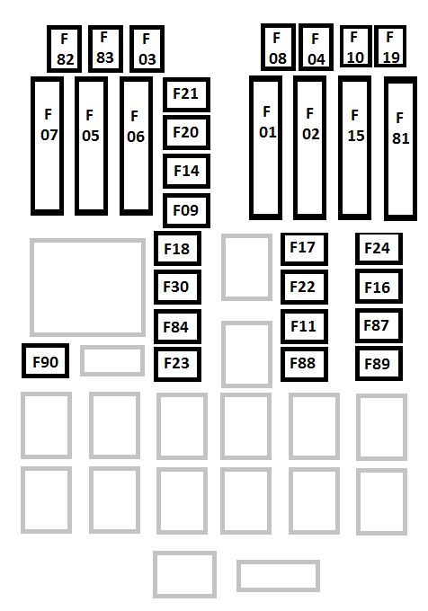
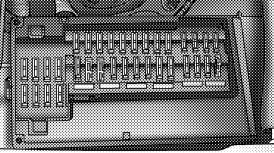
Engine Compartment Fuses
The engine compartment fuses are located under the hood on the driver’s side, between the brake master cylinder and the left front fender.
| Cavity | Fuse | Circuits |
| 1 | 5 | Garage Door Opening Signal, Tire Pressure Control and Seat Heate |
| 2 | 5 | Control Unit Airbag |
| 3 | 5 | Indicator, Safety Restraint System and Indicator, Passenger Airbag Off |
| 4 | 7,5 | Heated Mirror |
| 5 | 15 | Radio (Coupe) |
| 20 | Roof Control Module (Roadster) | |
| 6 | 40 | Roof Hydraulic Unit (Roadster) |
| 5 | Exterior Mirror Adjustment, Left And Right (Coupe) | |
| 7 | 5 | Occupation Classification Module (Right Seat) |
| 8 | 15 | Radio |
| 9 | 10 | Control Unit Airbag |
| 10 | 5 | Speed Control |
| 11 | 15 | Ignition Coil 6 Cyl. |
| 12 | 10 | Washer Liquid Heater, Washer Nozzle Heater |
| 13 | Roof Light, Horn, Anti-TheftAlarm, Trunk Light and Tire Pressure Control | |
| 14 | 10 | Diagnostic Socket |
| 15 | 5 | Climate Control, Auxiliary Water Pump |
| 16 | 30 | Spoiler Motor |
| 17 | 40 | Electronic Stability Program |
| 18 | 40 | Electronic Stability Program |
| 19 | 40 | Power Window, Front |
| 20 | 30 | Wiper Motor |
| 21 | 30 | Seat Adjustment Right Side |
| 22 | 30 | Seat Adjustment Left Side |
| 23 | 15 | Sound Booster (Amplifier) |
| 24 | 30 | Seat Heater |
| 25 | 20 | Pneumatic Control Unit, Rear Window Defroster |
| 26 | 20 | Central Locking |
| 30 | Spare (Coupe) | |
| 15 | Radio (Roadster | |
| 31 | 15 | Cigar Lighter, Glove Compartment Light |
| 32 | 15 | Wiper, Washer Pump, Headlight Flasher |
| 33 | 5 | Control Unit |
| 34 | Spare (Coupe) | |
| 30 | Climate Control (Roadster) | |
| 35 | 15 | Radio Frequency Remote Control, Hazard Warning Flasher, Instrument Cluster, Climate Control |
| 36 | 30 | Climate Control (Coupe) |
| 5 | Exterior Mirror Adjustment (Roadster) | |
| 37 | 7,5 | Circulating Air, Instrument Cluster, Radio Frequency Remote Control, Climate Control, Central Control Unit |
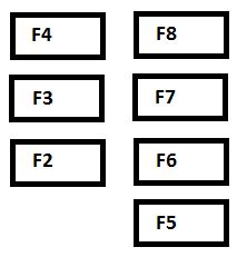
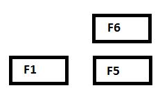
Relay Control Module Fuses
The relay control module fuses are located in the Control Module Box next to the battery in the engine compartment.
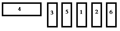
| Cavity | Fuse | Circuits |
| 1 | 15 | Traction System |
| 2 | 15 | Engine Control 2 |
| 3 | 15 | Engine Control 1 |
| 4 | 40 | Air Pump |
| 5 | 15 | Fuel Pump |
| 6 | 15 | Horn |
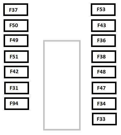
Interior Fuses
The fuse access door is located on the end of the instrument panel on the driver’s side behind the trim panel cover.
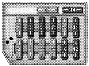
| Cavity | Fuse | Circuits |
| 1 | — | Not Assigned |
| 2 | 15 | Brake Lamp/Speed Control |
| 3 | 7.5 | Right High Beam, High Beam Indicator Light |
| 4 | 15 | Reverse/Turn signal Light |
| 5 | 7.5 | Left High Beam |
| 6 | 15 | Right Low Beam |
| 7 | 7.5 | Right Parking/Tail Light Side Marker |
| 8 | 15 | Left Low Beam |
| 9 | 15 | Fog Light |
| 10 | 7.5 | Left Parking/Tail Light Side Marker |
| 11 | 7.5 | License Plate/Instrument Cluster Lighting/Symbol Lighting |
| 12 | — | Not Used – Spare Fuse |
| 13 | — | Not Used – Spare Fuse |
| 14 | — | Not Used – Spare Fuse |
WARNING: Terminal and harness assignments for individual connectors will vary depending on vehicle equipment level, model, and market.