Jeep Patriot (2012) – fuse box diagram

Jeep Patriot (2012) – fuse box diagram

Year of production:  2012

Integrated power modul

The Integrated Power Module is located in the engine compartment near the air cleaner assembly.

Cavity Cartridge fuse Mini fuse Description
1 Empty Empty
2 15 AWD/4WD Control Module
3 10 Rear Center Brake Light Switch
4 10 Ignition Switch/Occupant Classification Module
5 20 Trailer Tow
6 10 Power Mirror/Steering Control Satellite Radio/HandsFree Phone
7 30 Ignition Off Draw
8 30 Ignition Off Draw
9 40 Power Seats
10 20 Power Locks/Interior Lighting
11 15 Power Outlet
12 20 115V AC Inverter
13 20 Cigar Lighter
14 10 Instrument Cluster
15 40 Radiator Fan
16 15 Dome Lamp/Sunroof/Rear Wiper Motor
17 10 Wireless Control Module
18 40 Auto Shutdown Relay
19 20 Radio Amplifiers
20 15 Radio
21 10 Intrusion Module/Siren – If Equipped
22 10 Heating, AC/Compass
23 15 Auto Shutdown Relay
24 15 Power Sunroof
25 10 Heated Mirror – If Equipped
26 15 Auto Shutdown Relay
27 10 Airbag Control Module
28 10 Airbag Control Module/Occupant Classification Module
29 Hot Car (No Fuse Required)
30 20 Heated Seat – If Equipped
31 10 Headlamp Washer – If Equipped
32 30 Auto Shutdown Relay
33 10 J1962 Conn/Powertrain Control Module
34 30 Antilock BrakeValve
35 40 Antilock Brake Pump
36 30 Headlamp/Washer Control/Smart Glass – If Equipped
37 25 Diesel Fuel Heater – If Equipped

WARNING: Terminal and harness assignments for individual connectors will vary depending on vehicle equipment level, model, and market.

Jeep Patriot (2010) – fuse box diagram

Jeep Patriot (2010) – fuse box diagram

Year of production:  2010

Integrated power modul

The Integrated Power Module is located in the engine compartment near the air cleaner assembly.

Cavity Cartridge fuse Mini fuse Description
1 Empty Empty
2 15 AWD/4WD ECU Feed
3 10 CHMSL Brake Switch Feed
4 10 Ignition Switch Feed/OCM
5 20 Trailer Tow
6 10 IOD Sw/Pwr Mir/Ocm Steering Cntrl Sdar/Hands Free Phone
7 30 IOD Sense1
8 30 IOD Sense2
9 40 Power Seats
10 20 CCN Power Locks/Interior Lighting
11 15 Power Outlet
12 20 Ign Run/Acc Inverter
13 20 Pwr Run/Acc Outlet RR/Dome Lamp/Cigar Lighter
14 10 IOD CCN
15 40 RAD Fan Relay Battery Feed
16 15 IGN Run/Acc Dome Lamp/Sunroof/Rear Wiper Motor/ACC Inverter
17 10 IOD Feed Mod-Wcm
18 40 ASD Relay Contact PWR Feed
19 20 PWR Amp 1 & Amp 2 Feed
20 15 IOD Feed Radio
21 10 IOD Feed Intrus Mod/Siren – If Equipped
22 10 IGN RUN Heat/AC/Compass Sensor
23 15 ENG ASD Relay Feed 3
24 15 Power Sunroof Feed
25 10 Heated Mirror – If Equipped
26 15 ENG ASD Relay Feed 2
27 10 IGN RUN Only ORC Feed
28 10 IGN RUN ORC/OCM Feed
29 Hot Car (No Fuse Required)
30 20 Heated Seat
31 10 Headlamp Washer – If Equipped
32 30 ENG ASD Control Feed 1
33 10 ABS MOD/J1962 Conn/PCM
34 30 ABS Valve Feed
35 40 ABS Pump Feed
36 30 Headlamp/Washer Control/Smart Glass – If Equipped
37 25 Diesel Fuel Heater – If Equipped

WARNING: Terminal and harness assignments for individual connectors will vary depending on vehicle equipment level, model, and market.

Jeep Patriot (2007 – 2008) – fuse box diagram

Jeep Patriot (2007 – 2008) – fuse box diagram

Year of production:  2007, 2008

Integrated power modul

The Integrated Power Module is located in the engine compartment near the air cleaner assembly.

Cavity Cartridge fuse Mini fuse Description
1 Empty Empty
2 15 AWD/4WD ECU Feed
3 10 CHMSL Brake Switch Feed
4 10 Ignition Switch Feed
5 20 Trailer Tow
6 10 IOD Sw/Pwr Mir/Ocm Steering Cntrl Sdar/Hands Free Phone
7 30 IOD Sense1
8 30 IOD Sense2
9 40 Power Seats
10 20 CCN Power Locks
11 15 Power Outlet
12 20 Ign Run/Acc Inverter
13 20 Pwr run/Acc Outlet RR
14 10 IOD CCN/ Interior Lighting
15 40 RAD Fan Relay Battery Feed
16 15 IGN Run/Acc Cigar Ltr/Sunroof
17 10 IOD Feed Mod-Wcm
18 40 ASD Relay Contact PWR Feed
19 20 PWR Amp 1 & Amp 2 Feed
20 15 IOD Feed Radio
21 10 IOD Feed Intrus Mod/Siren
22 10 IGN RUN Heat/AC/Compass Sensor
23 15 ENG ASD Relay Feed 3
24 15 Power Sunroof Feed
25 10 Heated Mirror
26 15 ENG ASD Relay Feed 2
27 10 IGN RUN Only ORC Feed
28 10 IGN RUN ORC/OCM Feed
29 Hot Car (No Fuse Required)
30 20 Heated Seat
31 10 Headlamp Washer – If Equipped
32 30 ENG ASD Control Feed 1
33 10 ABS MOD/J1962 Conn/PCM
34 30 ABS Valve Feed
35 40 ABS Pump Feed
36 30 Headlamp /Washer Control / Smart Glass
37 25 110 Inverter

WARNING: Terminal and harness assignments for individual connectors will vary depending on vehicle equipment level, model, and market.

Jeep Compass (2016 – 2017) – fuse box diagram

Jeep Compass (2016 – 2017) – fuse box diagram

Year of production: 2016, 2017

Integrated power module

The Integrated Power Module is located in the engine compartment near the air cleaner assembly.

Cavity Cartridge fuse Mini fuse Description
1 20 Trailer Tow – If Equipped
2 15 AWD/4WD Control Module – If Equipped
3 10 Rear Center Brake Light Switch
4 10 Ignition Switch/Clock Spring
5 20 Battery Feed For Power Tech
6 10 Power Mirror/Steering Control Satellite Radio/Hands-Free Phone
7 30 Ignition Off Draw
8 30 Ignition Off Draw
9 40 Power Seats
10 20 Power Locks/Interior Lighting
11 15 Power Outlet
12 20 115V AC Inverter – If Equipped
13 20 Cigar Lighter
14 10 Instrument Cluster
15 40 Radiator Fan
16 15 Dome Lamp/Sunroof/Rear Wiper Motor
17 10 Wireless Control Module
18 40 Auto Shutdown Relay
19 20 Radio Amplifiers
20 15 Radio
21 10 Intrusion Module/Siren – If Equipped
22 10 Heating, AC/Compass
23 15 Auto Shutdown Relay
24 15 Power Sunroof – If Equipped
25 10 Heated Mirror – If Equipped
26 15 Auto Shutdown Relay
27 10 Airbag Control Module
28 10 Airbag Control Module/Occupant Classification Module
29 Hot Vehicle (No Fuse Required)
30 20 Heated Seat – If Equipped
31 10 Headlamp Washer – If Equipped
32 30 Auto Shutdown Relay
33 10 J1962 Conn/Powertrain Control Module
34 30 Antilock BrakeValve
35 40 Antilock Brake Pump
36 30 Headlamp/Washer Control/Smart Glass – If Equipped
37 25 Diesel Fuel Heater – If Equipped

WARNING: Terminal and harness assignments for individual connectors will vary depending on vehicle equipment level, model, and market

Jeep Compass (2012) – fuse box diagram

Jeep Compass (2012) – fuse box diagram

Year of production: 2012

Integrated power module

The Integrated Power Module is located in the engine compartment near the air cleaner assembly.

Cavity Cartridge fuse Mini fuse Description
1 Empty Empty
2 15 AWD/4WD Control Module
3 10 Rear Center Brake Light Switch
4 10 Ignition Switch/Occupant Classification Module
5 20 Trailer Tow
6 10 Power Mirror/Steering Control Satellite Radio/HandsFree Phone
7 30 Ignition Off Draw
8 30 Ignition Off Draw
9 40 Power Seats
10 20 Power Locks/Interior Lighting
11 15 Power Outlet
12 20 115V AC Inverter
13 20 Cigar Lighter
14 10 Instrument Cluster
15 40 Radiator Fan
16 15 Dome Lamp/Sunroof/Rear Wiper Motor
17 10 Wireless Control Module
18 40 Auto Shutdown Relay
19 20 Radio Amplifiers
20 15 Radio
21 10 Intrusion Module/Siren – If Equipped
22 10 Heating, AC/Compass
23 15 Auto Shutdown Relay
24 15 Power Sunroof
25 10 Heated Mirror – If Equipped
26 15 Auto Shutdown Relay
27 10 Airbag Control Module
28 10 Airbag Control Module/Occupant Classification Module
29 Hot Car (No Fuse Required)
30 20 Heated Seat – If Equipped
31 10 Headlamp Washer – If Equipped
32 30 Auto Shutdown Relay
33 10 J1962 Conn/Powertrain Control Module
34 30 Antilock BrakeValve
35 40 Antilock Brake Pump
36 30 Headlamp/Washer Control/Smart Glass – If Equipped
37 25 Diesel Fuel Heater – If Equipped

WARNING: Terminal and harness assignments for individual connectors will vary depending on vehicle equipment level, model, and market

Jeep Compass (2010) – fuse box diagram

Jeep Compass (2010) – fuse box diagram

Year of production: 2010

Integrated power module

The Integrated Power Module is located in the engine compartment near the air cleaner assembly.

Cavity Cartridge fuse Mini fuse Description
1 Empty Empty
2 15 AWD/4WD ECU Feed
3 10 CHMSL Brake Switch Feed
4 10 Ignition Switch Feed/OCM
5 20 Trailer Tow
6 10 IOD Sw/Pwr Mir/Ocm Steering Cntrl Sdar/Hands Free Phone
7 30 IOD Sense 1
8 30 IOD Sense 2
9 40 Power Seats
10 20 CCN Power Locks/Interior Lighting
11 15 Power Outlet
12 20 Ign Run/Acc Inverter
13 20 Pwr Run/Acc Outlet RR/Dome Lamp/Cigar Lighter
14 10 IOD CCN
15 40 RAD Fan Relay Battery Feed
16 15 IGN Run/Acc Dome Lamp/Sunroof/Rear Wiper Motor/ACC Inverter
17 10 IOD Feed Mod-Wcm
18 40 ASD Relay Contact PWR Feed
19 20 PWR Amp 1 & Amp 2 Feed
20 15 IOD Feed Radio
21 10 IOD Feed Intrus Mod/Siren – If Equipped
22 10 IGN RUN Heat/AC/Compass Sensor
23 15 ENG ASD Relay Feed 3
24 15 Power Sunroof Feed
25 10 Heated Mirror – If Equipped
26 15 ENG ASD Relay Feed 2
27 10 IGN RUN Only ORC Feed
28 10 IGN RUN ORC/OCM Feed
29 Hot Car (No Fuse Required)
30 20 Heated Seat – If Equipped
31 10 Headlamp Washer Relay Control – if Equipped
32 30 ENG ASD Control Feed 1
33 10 ABS MOD/J1962 Conn/PCM
34 30 ABS Valve Feed
35 40 ABS Pump Feed
36 30 Headlamp/Washer Control/Smart Glass – If Equipped
37 25 Diesel Fuel Heater – If Equipped

WARNING: Terminal and harness assignments for individual connectors will vary depending on vehicle equipment level, model, and market

Jeep Compass (2008) – fuse box diagram

Jeep Compass (2008) – fuse box diagram

Year of production: 2008

Integrated power module

The Integrated Power Module is located in the engine compartment near the air cleaner assembly.

Cavity Cartridge fuse Mini fuse Description
1 Empty Empty
2 15 AWD/4WD ECU Feed
3 10 CHMSL Brake Switch Feed
4 10 Ignition Switch Feed
5 20 Trailer Tow
6 10 IOD Sw/Pwr Mir/Ocm Steering Cntrl Sdar/Hands Free Phone
7 30 IOD Sense 1
8 30 IOD Sense 2
9 40 Power Seats
10 20 CCN Power Locks
11 15 Power Outlet
12 20 Ign Run/Acc Inverter
13 20 Pwr run/Acc Outlet RR
14 10 IOD CCN/ Interior Lighting
15 40 RAD Fan Relay Battery Feed
16 15 IGN Run/Acc Cigar Ltr/Sunroof
17 10 IOD Feed Mod-Wcm
18 40 ASD Relay Contact PWR Feed
19 20 PWR Amp 1 & Amp 2 Feed
20 15 IOD Feed Radio
21 10 IOD Feed Intrus Mod/Siren
22 10 IGN RUN Heat/AC/Compass Sensor
23 15 ENG ASD Relay Feed 3
24 15 Power Sunroof Feed
25 10 Heated Mirror
26 15 ENG ASD Relay Feed 2
27 10 IGN RUN Only ORC Feed
28 10 IGN RUN ORC/OCM Feed
29 Hot Car (No Fuse Required)
30 20 Heated Seats
31 10 Headlamp Washer Relay Control
32 30 ENG ASD Control Feed 1
33 10 ABS MOD/J1962 Conn/PCM
34 30 ABS Valve Feed
35 40 ABS Pump Feed
36 30 Headlamp /Washer Control / Smart Glass
37 25 110 Inverter

WARNING: Terminal and harness assignments for individual connectors will vary depending on vehicle equipment level, model, and market

Jeep Commander XK (2006 – 2010) – fuse box diagram

Jeep Commander XK (2006 – 2010) – fuse box diagram

Year of production: 2006, 2007, 2008, 2009, 2010

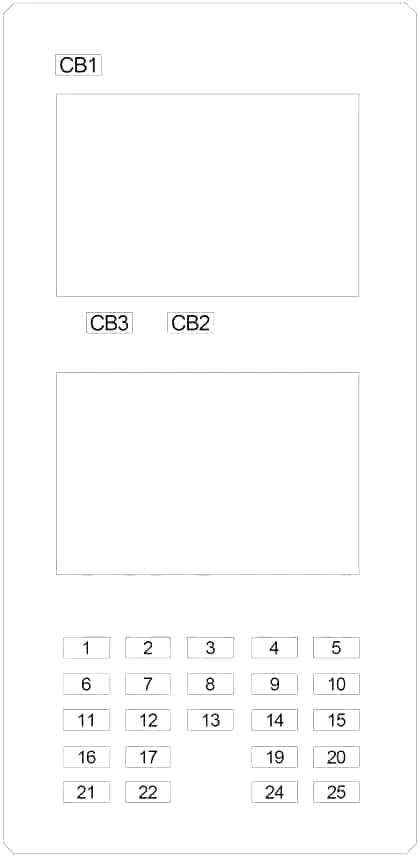
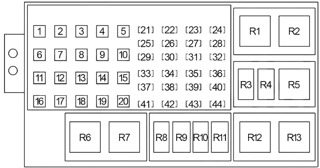
Passenger Compartment Fuse Box

The fuse panel is on the lower instrument panel just to the left of the steering column

Jeep Commander XK - fuse box diagram - passenger compartment
Jeep Commander XK – fuse box diagram – passenger compartment
Fuses specifications
No. A Description
1 30 Audio Amplifier
2 15 Sunroof Module
3 10 Heated Mirror
4 20 Rear Power Outlet
5 10 Rear HVAC
6 10 ’06-’07: Occupant Classification Module
7 20 Door Lock Relay, Driver Door Unlock Relay, Passenger Door Unlock Relay
8 15 ’06-’07: Steering Column Lock
9 20 Power Outlet (Console)
10 10 Rear Window Defogger Relay, Blower Motor Relay, Upper Switch Bank, Lower Switch Bank, A/C Heater Control, Final Drive Control Module, Park Assist Module, Electronic Overhead Module, Inside Rearview Mirror
11  –
12 10 Courtesy Lamp, Glove Box Lamp, Cargo Lamp, Vanity Lamp, Door Handle Lamp, Mirror Switch, Memory Mirror Module
13 10 ’08-’10: Automatic Windshield Wipers (Rain Sensor)
14 20 Power Outlet (Instrument Panel)
15 10 Tire Pressure Monitoring System, Fuse (Engine Compartment No.2): “30”
16 10 Cluster, Steering Control Module, Data Link Connector
17 15 Flip-Up Glass Relay
18  –
19 10 ’06-’07: Occupant Classification Module
20 10 Sentry Key Remote Entry Module (’05-’08), Cluster, Steering Column Control Module (’08-’10), BUX Trailer Tow (’08-’10)
21 15 ’06-’07: Automatic Windshield Wipers (Rain Sensor)
22 15 Rear Wiper Relay
23  –
24 10 Transmission Relay, Air Conditioner Compressor Clutch Relay, Fuel Pump Relay, Stop Lamp Switch (5.7L), Powertrain Control Module, Front Control Module
25 10 Stop Lamp Inhibit Relay, ABS, Transfer Case Selector Switch, Trailer Sway Damp Relay
Circuit Breaker
CB1 20 Wiper (On/Off) Relay (Wiper (High/Low) Relay)
CB2 20 Power Seat, Heated Seat Module
CB3 20 Power Window, Door Lock, Mirror Switch
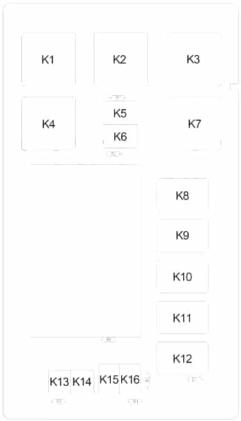
Relay
Jeep Commander XK - fuse box diagram - passenger compartment (relay)
Jeep Commander XK – fuse box diagram – passenger compartment (relay)
No. Description
R1  –
R2 Power Outlet
R3  –
R4 Rear Window Defogger
R5 Run/Accessory
R6 Run
R7 Run/Accessory Delay
R8 Stop Lamp Inhibit
R9  –
R10  –
R11 Flip-Up Glas
R12 Transmission
R13 Door Lock
R14 Driver Door Unlock
R15 Passenger Door Unlock
R16 Rear Wiper

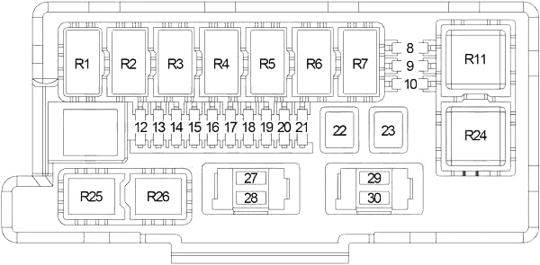
Engine Compartment Fuse Box (No.1)

Jeep Commander XK - fuse box diagram - engine compartment (box no. 1)
Jeep Commander XK – fuse box diagram – engine compartment (box no. 1)
Fuses specification
No. A Description
8 10 Left Headlamp, Left Tail Lamp, License Lamp,
9 10 Trailer Tow Connector
10 10 Right Headlamp, Right Tail Lamp, Cluster, Upper Switch Bank
12 20 Front Control Module
13 20 Front Control Module
14 20 Adjustable Pedals Relay
15 20 Front Fog Lamp Relay
16 20 Horn Relay
17 20 Rear Wiper
18 20 Front Control Module
19 20 Trailer Tow (Left Turn) Relay
20 20 Front Control Module
21 20 Trailer Tow (Right Turn) Relay
22 30 Final Drive Control Module
23 50 Radiator Fan (High Speed) Relay, Radiator Fan (Low Speed) Relay
27 15 Front Control Module, Sentry Key Remote Entry Module, Electronic Overhead Console, Satellite Receiver
28 20 Radio
29 10 Occupant Restraint Controller Module
30 10 Occupant Restraint Controller Module
Relay
R1 Wiper (On/Off)
R2 Wiper (High/Low)
R3 Horn
R4  –
R5 Trailer Tow (Left Turn)
R6 Trailer Tow (Right Turn)
R7 Park Lamp
R11 Radiator Fan (High Speed)
R24 Radiator Fan (Low Speed)
R25 Front Fog Lamp
R26 Adjustable Pedals

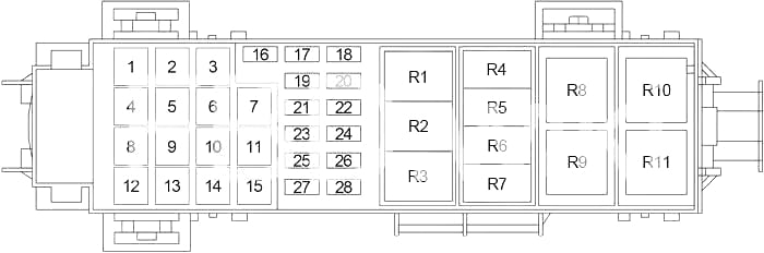
Engine Compartment Fuse Box (No.2) (’06-’07)

Jeep Commander XK - fuse box diagram - engine compartment (box no. 2 - 2006 - 2007)
Jeep Commander XK – fuse box diagram – engine compartment (box no. 2 – 2006 – 2007)
Fuse specifications
No. A Description
1 40 Blower Motor Relay
2 30 Fuse (Passenger Compartment): “4”, “9”
3 30 Run Relay, Fuse (Passenger Compartment): “12”, “17”, “22”
4 30 ABS
5 50 Diesel: PTC No.1
6 50 Auto Shut Down Relay (Powertrain Control Module, Fuse: “16”)
7 30 Rear Blower
8 40 Run/Accessory Delay Relay, Fuse (Passenger Compartment): “2”, “7”, “8”, “CB2”
9  –
10 40 Starter Relay, Run/Accessory Relay, Fuse (Passenger Compartment): “CB1”
11 30 Power Outlet Relay, Trailer Tow
12 40 Rear Window Defogger Relay
13 40 Run Relay, Run/Accessory Relay, Rear Wiper Relay, Door Lock Relay, Driver Door Unlock Relay, Passenger Door Unlock Relay, Fuse (Passenger Compartment): “1”, “6”, “16”
14 50 Diesel: PTC No.2
15 50 Diesel: PTC No.3
16 25 Zener Diode, Front Control Module, Ignition Coils (3.7L, 4.7L, 5.7L), Ignition Capacitor (3.7L, 4.7L)
17  –
18 20 Air Conditioner Compressor Clutch Relay, Transmission Control Relay (4.7L, 5.7L)
19 20 Ignition Switch (Starter Relay, Powertrain Control Module, Fuse (Passenger Compartment): “19”, “20”, “24”, “25”)
20 20 Powertrain Control Module
21 30 ABS
22  –
23 20 Final Drive Control Module
24 20 Fuel Pump Relay
25 20 Final Drive Control Module
26 15 Diesel: Powertrain Control Module
27 15 Stop Lamp Switch
28 25 Fuel Injectors, Powertrain Control Module
Relay
R1  –
R2  –
R3 Diesel: PTC (No.1)
R4 Transmission Control
R5 Starter
R6 Air Conditioner Compressor Clutch
R7 Fuel Pump
R8 Diesel: PTC (No.3)
R9 Diesel: PTC (No.2)
R10 Blower Motor
R11 Auto Shut Down

Engine Compartment Fuse Box (No.2) (’08-’10)

Jeep Commander XK - fuse box diagram - engine compartment (box no. 2 - 2008 - 2010)
Jeep Commander XK – fuse box diagram – engine compartment (box no. 2 – 2008 – 2010)
Fuse specifications
No. A Description
1 50 Diesel: PTC (No.1)
2 40 HID Headlamps
3 50 Diesel: PTC (No.2)
4 30 Power Outlets
5 50 Diesel: PTC (No.3)
6 30 Cigarette Lighter, Trailer Tow Battery
7 40 Power Liftgate
8 40 Starter, JB Power
9 20 Front Power Windows
10  –
11 40 Blower Motor Relay
12 30 Rear Wiper, Ign R/O
13 40 Rear Window Defroster, Heated Mirror
14 30 Rear Blower Motor
15  –
16 50 Auto Shut Down Relay
17 30 ABS Pump
18 40 Accessory Delay, Power Seats
19 40 JB Power
20 30 Front Wiper Motor
21 20 Fuel Pump
22 20 Transmission Control Module (TCM), Air Conditioner Compressor Clutch
23 25 Power Inverter
24 20 Rear Heated Seats
25 20 Final Drive Control Module (FDCM)
26 15 Stop-Lamps
27 20 Headlamp Washer
28 30 ABS Valves
29 20 Gasoline: Powertrain Control Module (PCM)
30  –
31  –
32 15 Diesel: Powertrain Control Module
33 20 E-Diff – Final Drive Control Module (FDCM)
34  –
35 20 Trailer Tow Module (BUX Only)
36  –
37 20 Ignition Switch
38 20 Left Headlamp (HID)
39 20 Right Headlamp (HID)
40 25 Next Generation Controller (NGC), Injectors
41 20 Subwoofer
42  –
43 25 Coils, Actuators
44  –
Relay
R1  –
R2 Diesel: PTC (No.3)
R3 Transmission Control
R4 Headlamp Washer
R5 HID Headlamps
R6 Diesel: PTC (No.1)
R7 Diesel: PTC (No.2)
R8 Ignition (Run/Start)
R9 Air Conditioner Compressor Clutch
R10 Fuel Pump
R11 Starter
R12 Blower Motor
R13 Auto Shut Down

WARNING: Terminal and harness assignments for individual connectors will vary depending on vehicle equipment level, model, and market.

Jeep Commander (2007) – fuse box diagram

Jeep Commander (2007) – fuse box diagram

Year of production: 2007

Interior Fuses

The fuse panel is on the lower instrument panel just to the left of the steering column

Cavity Cartridge fuse Mini fuse Description
1 30 Audio Amp (B+)
2 15 Sunroof (B+)
3 10 Htd Mirror (EBL)
4 20 Rr Pwr Out (B+)
5 10 Rr HVAC (R/O)
6 Spare (B+)
7 20 Door Locks (B+)
8 15 Steer Col Lock (B+)
9 20 Pwr Outlet (B+)
10 10 Final Drive Control Module (FDCM), Heater Ventilation, Air Conditioning (HVAC), Switch Bank, Transfer Case Switch, O/H, Heater Ventilation, Air Conditioning (HVAC) Relay, Rear Park Assist
11 Spare (B+)
12 10 Door Mods, Mem. Sw, O/H Lamps, IP Courtesy Lamps, Glove Box Lamp (B+)
13 10 Autowipe (R/A)
14 20 Cigar Ltr (R/A)
15 10 Tire Pressure Transducers (R/O)
16 10 Steering Control Module (SCM), Diag. Connector, Cluster (B+)
17 15 Flipper Glass (B+)
19 Spare (R/S)
20 10 Sentry Key Remote Entry Module (SKREEM), Cluster (R/S)
21 Spare (Acc Delay)
22 15 Rear Wiper (B+)
24 10 Power Distribution Center (PDC) Relays, Final Drive Control Module (FDCM), Front Control Module (FCM) (R/S), A580 (R/S)
25 10 Shifter Assy (BTSI), Trans. Case Switch, ESP/ABS, Brake Supp Rly Coil (R/S)

Underhood Fuses (Power Distribution Center)

Cavity Cartridge fuse Mini fuse Description
1 40 HVAC Blower
2 30 Power Outlets
3 30 Rr Wiper/Ign R/O
4 30 ABS Pump
5 50 Cabin Htr 1 (Diesel Only
6 50 Auto Shut Down (ASD)
7 30 Rr HVAC (XK Only)
8 40 Acc Delay/Seats
9 40 Pwr Liftgate (XK Only)
10 40 Starter/Junction Block (JB) Power
11 30 Cig Ltr/T-Tow
12 40 Rear Window Defogger (EBL)/Htd Mirror
13 40 Junction Block (JB) Power
14 50 Cabin Htr 2 (Diesel Only)
15 50 Cabin Htr 3 (Diesel Only
16 25 Integrated Power Module (IPM)/Coils
17 Spare
18 20 EATX/AC Clutch
19 20 Ign Sw
20 20 PCM Batt (Gasoline Only)
21 30 ABS Valves
22 20 T-Tow (BUX)
23 20 Final Drive Control Module (FDCM)
24 20 Fuel Pump
25 20 Final Drive Control Module (FDCM
26 15 Powertrain Control Module (PCM) Auto Shut Down (ASD) (Diesel Only)
27 15 Brake/Stop Lamps
28 25 Next Generation Controller (NGC)/Injectors
29 Spare
30 Spare

Underhood Fuses (Integrated Power Module)

Cavity Cartridge fuse Mini fuse Description
8 10 Lt Park Lamps
9 10 Trailer-Tow Park Lamps
10 10 Rt Park Lamps
12 20 Front Control Module (FCM) Batt #4
13 20 Front Control Module (FCM) Batt #2
14 20 Adjustable Pedal
15 20 Ft Fog Lamps
16 20 Horn
17 20 Rear Fogs
18 20 Front Control Module (FCM) Batt #1
19 20 Lt Trailer-Tow Stop/Turn
20 20 Front Control Module (FCM) Batt #3
21 20 Rt T-Tow Stop/Turn
22 30 Final Drive Control Module (FDCM) MOD
23 50 Radiator Fan
27 15 Ignition Off Draw (IOD) #1
28 20 Ignition Off Draw (IOD) #2
29 10 Occupant Restraint Controller (ORC) R/S
30 10 Occupant Restraint Controller (ORC) R/O

WARNING: Terminal and harness assignments for individual connectors will vary depending on vehicle equipment level, model, and market.

Jeep Commander (2006) – fuse box diagram

Jeep Commander (2006) – fuse box diagram

Year of production: 2006

Interior Fuses

The fuse panel is on the lower instrument panel just to the left of the steering column

Cavity Ampere rating [A] Description
1 30 Audio Amp (B+)
2 15 Sunroof (B+)
3 10 Htd Mirror (EBL)
4 20 Rr Pwr Out (B+)
5 10 Rr HVAC (R/O)
6 10 OCM (B+)
7 20 Door Locks (B+)
8 15 Steer Col Lock (B+)
9 20 Pwr Outlet (B+)
10 10 Ign Run Only Out (R/O)
11 Spare
12 10 Mem. Sw, Courtesy Lamp (B+
13 Spare
14 20 Cigar Ltr (R/A)
15 10 Tire Press Mon (R/O)
16 10 SCM, Cluster OBD (B+)
17 15 Flipper Glass (B+)
19 10 OCM (R/S)
20 10 WCM, Cluster (R/S)
21 15 Autowipe (Accy Delay)
22 15 Rear Wiper (B+)
24 10 PDC, FCM, A580 (R/S)
25 10 ABS, Trans. Case Switch (R/S)
CB1 20 Cycle -Wipers (B+)
CB2 20 Non – Cycle Seats (B+)
CB3 20 Non – Cycle Windows (Delay)

Underhood Fuses (Power Distribution Center)

Cavity Ampere rating [A] Description
1 40 HVAC Blower
2 30 Power Outlets
3 30 Rr Wiper/Ign R/O
4 30 ABS Pump
5 50 Cabin Htr 1 (Diesel Only
6 50 ASD
7 30 Rr HVAC (XK)
8 40 Acc Delay/Seats
9 Spare
10 40 Starter/JB Power
11 30 Cig Ltr/T-Tow
12 40 EBL/Htd Mirror
13 40 JB Power
14 50 Cabin Htr 2 (Diesel Only)
15 50 Cabin Htr 3 (Diesel Only
16 25 IPM/Coils
17 Spare
18 20 TCM/AC Clutch
19 20 Ign Sw
20 20 PCM Batt (Gasoline Only)
21 30 ABS Valves
22 Spare
23 20 FDCM
24 20 Fuel Pump
25 20 FDCM/E-Diff
26 15 Hyd/PCM (Diesel Only
27 15 Brake/Stop Lamps
28 25 NGC/Injectors
29 Spare
30 Spare
31 Mini Relay Cabin Htr 1 Rly (Diesel Only)
32 Micro Relay TCM Rly (Gasoline Only
33 Micro Relay Starter Rly
34 Micro Relay AC Clutch Rly
35 Micro Relay Fuel Pump Rly
36 Mini Relay Cabin Htr 3 Rly (Diesel Only)
38 Mini Relay Cabin Htr 2 Rly (Diesel Only)
39 Mini Relay HVAC Blower Rly
40 Mini Relay ASD Rly

Underhood Fuses (Integrated Power Module)

Cavity Ampere rating [A] Description
1 Micro Relay Wiper On/Off Rly
2 Micro Relay Wiper Hi/Lo Rly
3 Micro Relay Horn Rly
4 Micro Relay Rear Fog Rly (BUX Only
5 Micro Relay Lt T-Tow Stop/Turn Rly
6 Micro Relay Rt T-Tow Stop/Turn Rly
7 Micro Relay Park Lamps Rly
8 10 Lt Park Lamps
9 10 T-Tow Park Lamps
10 10 Rt Park Lamps
11 Mini Relay Rad Fan Hi Rly
12 20 FCM Batt #4
13 20 FCM Batt #2
14 20 Adjustable Pedal
15 20 Ft Fog Lamps
16 20 Horn
17 20 Rear Fogs
18 20 FCM Batt #1
19 20 Lt T-Tow Stop/Turn
20 20 FCM Batt #3
21 20 Rt T-Tow Stop/Turn
22 30 FDCM Mod
23 50 Rad Fan
24 Mini Relay Rad Fan Lo Rly
25 Micro Relay Ft Fog Lamps Rl
26 Micro Relay Adjustable Pedal Rly
27 15 IOD #1
28 20 IOD #2 (Audio)
29 10 ORC (Ign R/.S)
30 10 ORC (Ign R/O)

WARNING: Terminal and harness assignments for individual connectors will vary depending on vehicle equipment level, model, and market.