Chevrolet Malibu (2016) – fuse box diagram
Year of production: 2016
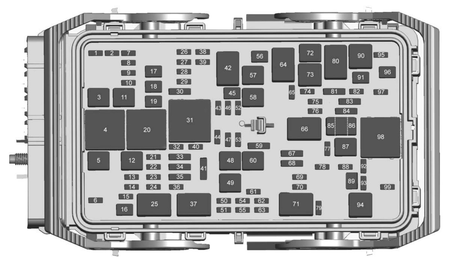
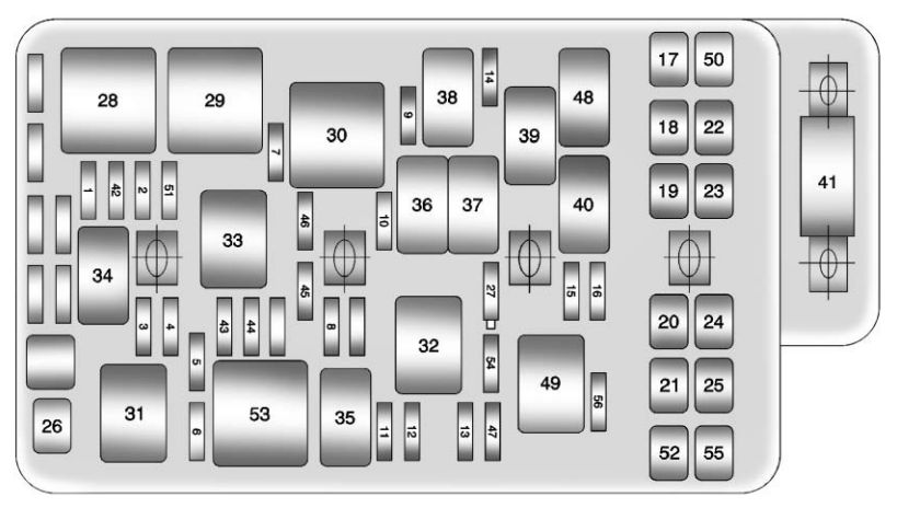
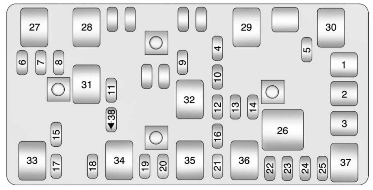
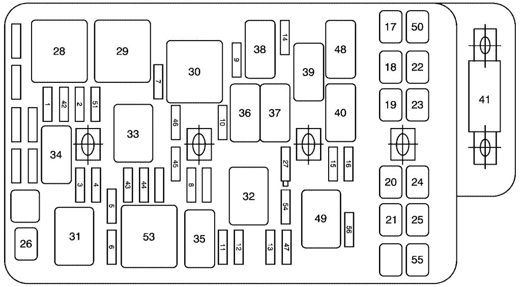
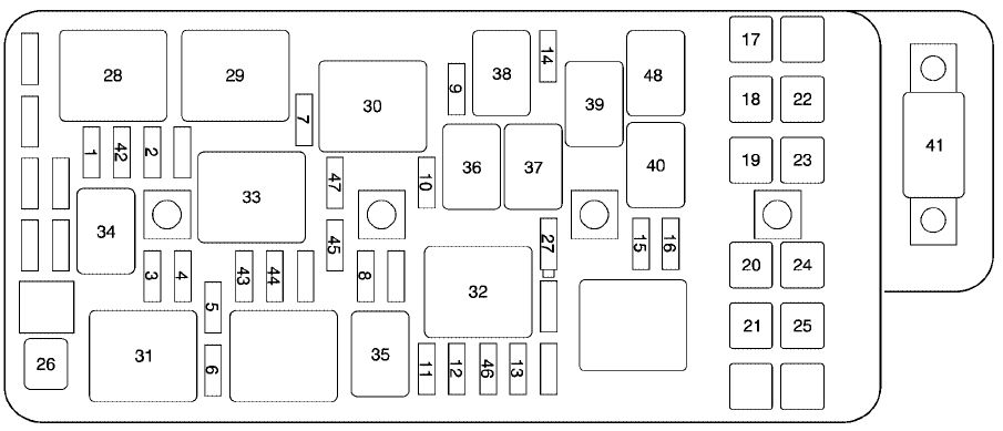
Engine Compartment Fuse Block
The engine compartment fuse block is on the driver side of the engine compartment, near the battery.
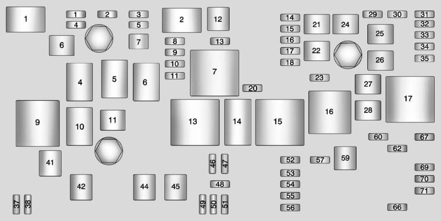
| Mini fuses | Usage |
| 1 | Transmission Control Module Battery |
| 2 | Engine Control Module Battery (LTG)/Air Conditioning Compressor Clutch (LKW) |
| 3 | Air Conditioning Compressor Clutch (LTG) |
| 4 | Air Conditioning Compressor Clutch (LTG) |
| 5 | Engine Control Module Battery (LKW) |
| 7 | Engine Control Module Battery (LKW) |
| 8 | Spare |
| 9 | Ignition Coils |
| 10 | Engine Control Module |
| 11 | Emissions |
| 13 | Transmission Module Ignition |
| 14 | Cabin Heater Coolant Pump |
| 15 | Spare |
| 16 | Aero Shutter |
| 17 | Spare |
| 18 | R/C Dual Battery Isolator Module |
| 20 | Transmission Auxiliary Oil Pump (LKW) |
| 23 | Spare (LKW) |
| 29 | Left Seat Power Lumber Control |
| 30 | Right Seat Power Lumber Control |
| 31 | Chassis Control Module |
| 32 | Back-Up Lamps/ Interior Lamps |
| 33 | Front Heated Seats |
| 34 | Antilock Brake System Valve |
| 35 | Amplifier |
| 37 | Right High Beam |
| 38 | Left High Beam |
| 46 | Cooling Fan |
| 47 | Emissions |
| 48 | Foglamp |
| 49 | Low Beam HID Headlamp Right |
| 50 | Low Beam HID Headlamp Left |
| 51 | Horn/Dual Horn |
| 52 | Cluster Ignition |
| 53 | Inside Rearview Mirror/Rear Camera/ Fuel Module Ignition |
| 54 | Heating, Ventilation, and Air Conditioning Module Ignition |
| 55 | Front Power Windows/Mirrors |
| 56 | Windshield Washer |
| 57 | Spare |
| 60 | Heated Mirror |
| 62 | Canister Vent Solenoid |
| 66 | Spare |
| 67 | Fuel Module |
| 69 | Battery Voltage Sensor |
| 70 | Lane Departure/Rear Parking Aid/Side Blind Zone Assist |
| 71 | PEPS BATT |
| J-Case Fuses | Usage |
| 6 | Front Wiper |
| 12 | Starter 1 |
| 21 | Rear Power Window |
| 22 | Sunroof |
| 24 | Front Power Window |
| 25 | PEPS MTR |
| 26 | Antilock Brake System Pump |
| 27 | Not Used |
| 28 | Rear Defogger |
| 41 | Brake Vacuum Pump |
| 42 | Cooling Fan K2 |
| 44 | Starter 2 |
| 45 | Cooling Fan K1 |
| 59 | Air Pump Emissions |
| Mini Relays | Usage |
| 7 | Powertrain |
| 9 | Cooling Fan K2 |
| 13 | Cooling Fan K1 |
| 15 | Run/Crank |
| 16 | Spare |
| 17 | Window/Mirror Defogger |
| Micro Relays | Usage |
| 1 | Air Conditioning Compressor Clutch |
| 2 | Starter Solenoid |
| 4 | Front Wiper Speed |
| 5 | Front Wiper On |
| 6 | Spare |
| 8 | Transmission Auxiliary Oil Pump (LKW) |
| 10 | Cooling Fan K3 |
| 11 | Starter 2 Solenoid (LKW) |
| 14 | Headlamp Low Beam/DRL |
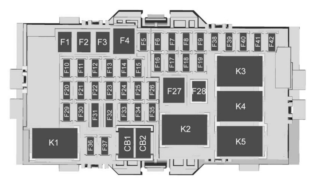
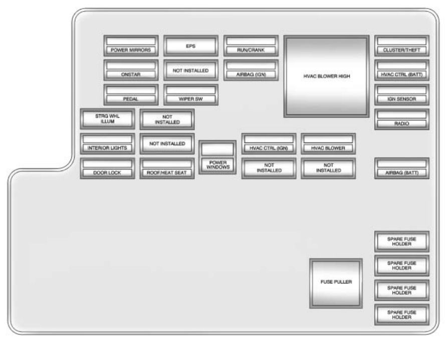
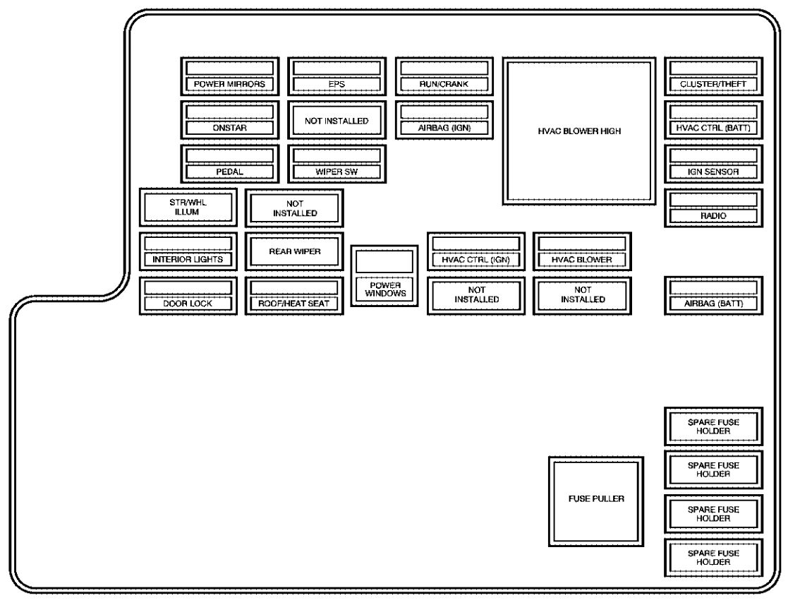
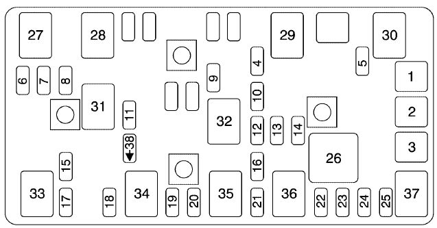
Instrument Panel Fuse Block
The instrument panel fuse block is in the instrument panel, on the driver side of the vehicle.
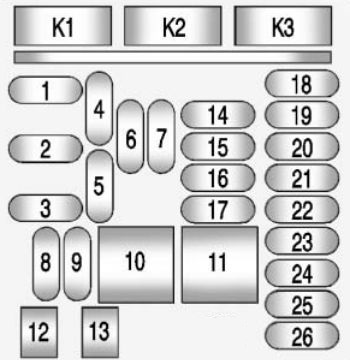
| Fuses | Usage |
| 1 | Steering Wheel Controls Backlight |
| 2 | Right Rear Turn Signal, Left Mirror Turn Signal, Left Front Turn Signal, Door Locks |
| 3 | Left Stoplamp, Left DRL Lamp, Headlamp Control, Right Taillamp, Right Park/Sidemarker Lamps, Right Mirror Turn, Right Front Turn Signals |
| 4 | Radio |
| 5 | OnStar (If Equipped) |
| 6 | Front Accessory Power Outlet |
| 7 | Console Bin Power Outlet |
| 8 | License Plate Lamp, Center High-Mounted Stoplamp, Rear Fog Lamps, Right Front Park/Sidemarker Lamps, LED Indicator Dim, Washer Pump, Right Stoplamp, Trunk Release |
| 9 | Left Low-Beam Headlamp, DRL |
| 10 | Body Control Module 8 (J-Case Fuse), Power Locks |
| 11 | Front Heater Ventilation Air Conditioning/Blower (J-Case Fuse) |
| 12 | Passenger Seat (Circuit Breaker) |
| 13 | Driver Seat (Circuit Breaker) |
| 14 | Diagnostic Link Connector |
| 15 | Airbag, SDM |
| 16 | Trunk Release |
| 17 | Heater Ventilation Air Conditioning Controller |
| 18 | Audio Main |
| 19 | Displays |
| 20 | Passenger Occupant Sensor |
| 21 | Instrument Cluster |
| 22 | Ignition Switch |
| 23 | Right Low-Beam Headlamp, DRL |
| 24 | Ambient Light, Switch Backlighting (LED), Trunk Lamp, Shift Lock, Key Capture |
| 25 | 110V AC |
| 26 | Spare |
| Relays | Usage |
| K1 | Trunk Release |
| K2 | Not used |
| K3 | Power Outlet Relay |
WARNING: Terminal and harness assignments for individual connectors will vary depending on vehicle equipment level, model, and market.