Chevrolet Malibu (2001) – fuse box diagram
Year of production: 2001
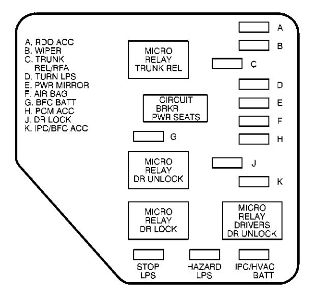
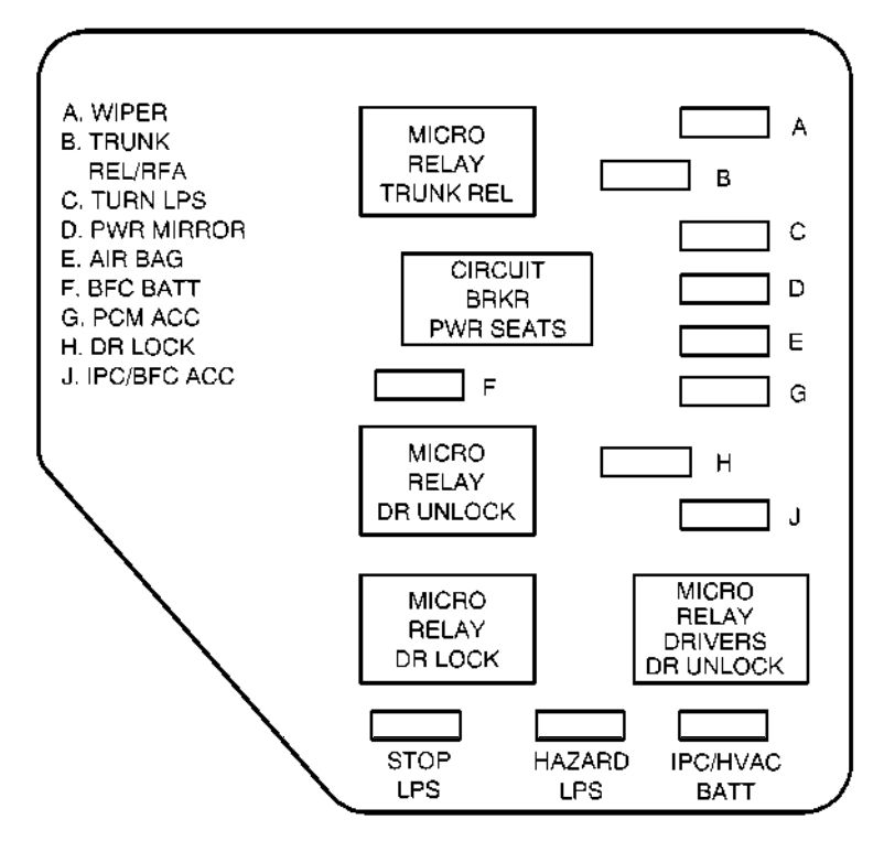
Instrument Panel Fuse Block-Left
| Fuse | Usage |
| A | Wipers |
| B | Trunk relase and remote lock control |
| C | Turn signal |
| D | Power mirrors |
| E | Air bag |
| F | Body Function Control Module |
| G | Powertrain Control Module |
| H | Door Locks |
| J | Body Function Control Module, Cluster |
| MICRO RELAY TRUNK REL | Remote Trunk Release |
| CIRCUIT BRKR PWR SEATS | Power Seats |
| MICRO RELAY DR UNLOC | Door Locks |
| MICRO RELAY DR LOCK | Door Locks |
| MICRO RELAY DRIVERS DR UNLOCK | Door Locks |
| STOP LPS | Stoplamps |
| HAZARD LPS | Hazard Lamps |
| IPC/HVAC BATT | Cluster, Climate Control |
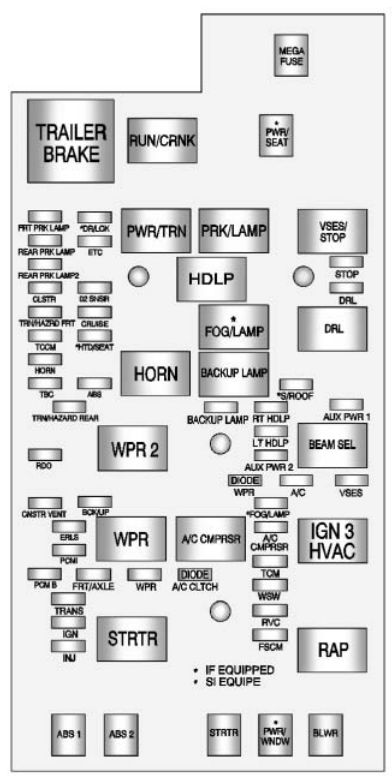
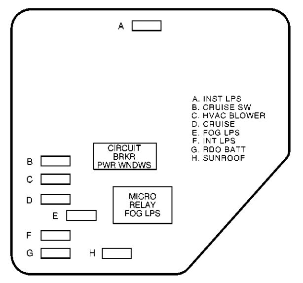
Instrument Panel Fuse Block-Right
| Fuse | Usage |
| A | Instrument Panel Lights, Dimmer |
| B | Cruise Control Switches |
| C | Climate Control System |
| D | Cruise Control |
| E | Fog Lamps |
| F | Interior Lamps, Body Function Control Module |
| G | Radio |
| H | Sunroof |
| CIRCUIT BRKR PWR WNDWS | Power Windows |
| MICRO RELAY FOG LPS | Fog Lamps |
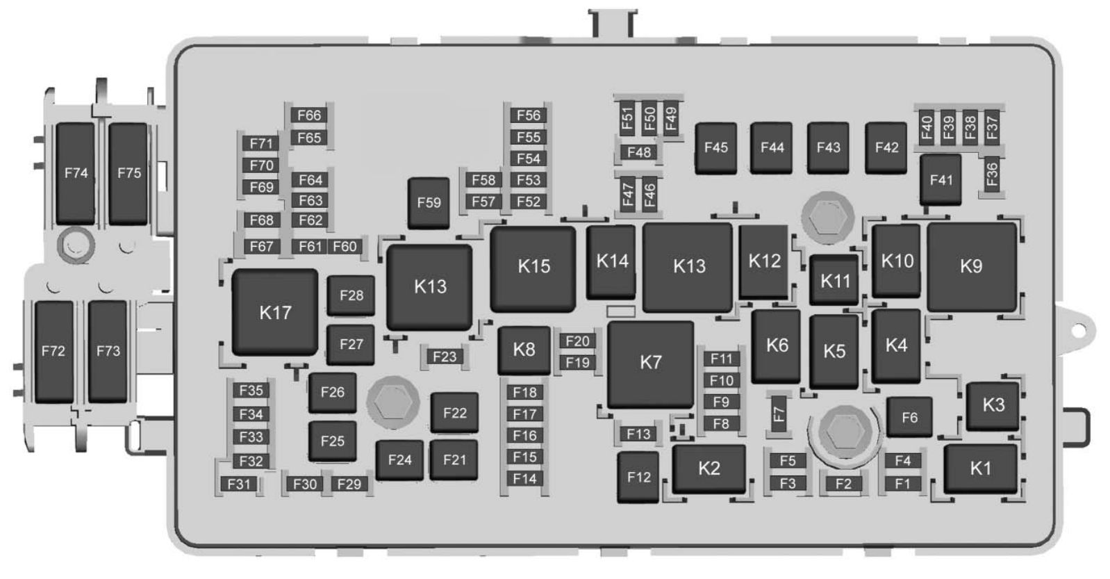
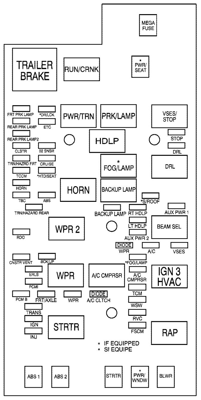
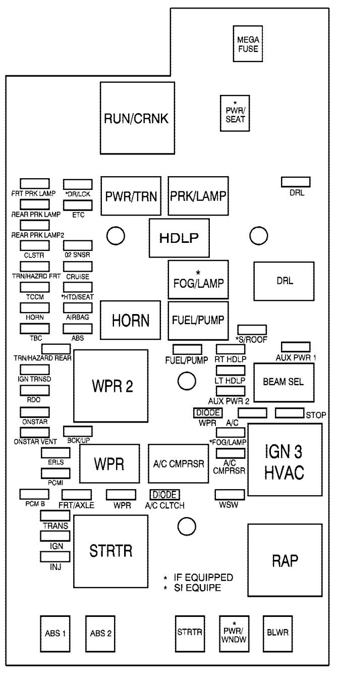
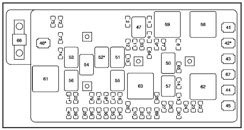
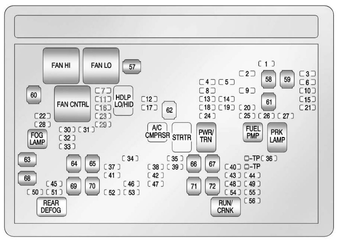
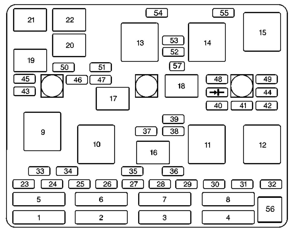
Engine Compartment Fuse Block
The engine compartment fuse block is located on the driver’s side of the engine compartment, near the air cleaner filter.
| Maxi-fuses | Usage |
| 1 | Ignition Switch |
| 2 | Right Electrical Center-Fog Lamps, Radio, Body Function Control Module, Interior Lamps |
| 3 | Left Electrical Center -Stoplamps, Hazard Lamps, Body Function Control Module, Cluster, Climate Control System |
| 4 | Anti-Lock Brakes |
| 5 | Ignition Switch |
| 6 | Not Used |
| 7 | Left Electrical Center-Power Seats, Power Mirrors, Door Locks, Trunk Release and Remote Lock Control |
| 8 | Cooling Fans #1 |
| Mini-Relays | Usage |
| 9 | Rear Defog |
| 10 | Not Used |
| 11 | Not Used |
| 12 | Cooling Fan #1 |
| 13 | HVAC Blower (Climate Control) |
| 14 | Cooling Fan #2 |
| 15 | Cooling Fan |
| Micro-Relays | Usage |
| 16 | Air Conditioning Compressor |
| 17 | Not Used |
| 18 | Fuel Pump |
| 19 | Automatic Light Control |
| 20 | Automatic Light Control |
| 21 | Horn |
| 22 | Daytime Running Lamps |
| Mini-Fuses | Usage |
| 23 | Spare Fuse Holder |
| 24 | Spare Fuse Holder |
| 25 | Spare Fuse Holder |
| 26 | Spare Fuse Holder |
| 27 | Spare Fuse Holder |
| 28 | Spare Fuse Holder |
| 29 | Spare Fuse Holder |
| 30 | Spare Fuse Holder |
| 31 | Spare Fuse Holder |
| 32 | Spare Fuse Holder |
| 33 | Rear Defog |
| 34 | Accessory Power Outlets, Cigar Lighter |
| 35 | Generator |
| 36 | Not Used |
| 37 | Air Conditioning Compressor, Body Function Control Module |
| 38 | Automatic Transaxle |
| 39 | Powertrain Control Module, Ignition |
| 40 | Anti-Lock Brakes |
| 41 | Ignition System |
| 42 | Back-Up Lamps, Brake Transaxle Shift Interlock |
| 43 | Horn |
| 44 | Powertrain Control Module |
| 45 | Parking Lamps |
| 46 | Climate Control System |
| 47 | Canister Purge Valve, Powertrain Control Module, Exhaust Gas Recirculation, Heated O2 Sensor |
| 48 | Fuel Pump, Injectors |
| 49 | Not Used |
| 50 | Right Headlamp |
| 51 | Left Headlamp |
| 52 | Cooling Fan |
| 53 | HVAC Blower (Climate Control ) |
| 54 | Not Used |
| 55 | Cooling Fan #2 Ground |
| 56 | Fuse Puller |
| 57 | Not Used |
WARNING: Terminal and harness assignments for individual connectors will vary depending on vehicle equipment level, model, and market.