AMC Pacer (1975 – 1979) – fuse box diagram
Year of production: 1975, 1976, 1977, 1978, 1979
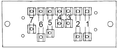
Type 1
| No. |
A |
Protected Component |
| 1 | 20 | Turn signal, back-up lights, radio, windshield washer |
| 2 | 20 | Blower motor, air conditioner clutch |
| 3 | 4 | Interlock module circuit, headlight warning buzzer, oil light indicator, park brake, brake failure circuit |
| 4 | 4 | Panel illumination lights |
| 5 | 14 | Interlock module circuit, windshield wiper, park, tail, license and side marker lights |
| 6 | 20 | Stop light and hazard warning flasher |
| 7 | 9 | Dome, courtesy, glove box, trunk and cargo lights, clock |
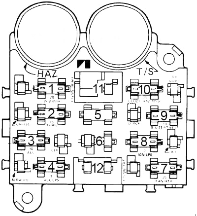
Type 2
| No. |
A |
Protected Component |
| 1 | 10 | Parking lights, key/headlight warning buzzer |
| 2 | 15 | Hazard warning, stoplights |
| 3 | 10 | Clock; dome and trunk lights |
| 4 | 3 | Cluster illumination |
| 5 | – | – |
| 6 | 10 | Radio, cigar lighter |
| 7 | 25 | Heater/A/C blower motor, A/C clutch |
| 8 | 7.5 | Gauges, Seat belt warning |
| 9 | 20 | Turn signals, backup lights, windshield washers |
| 10 | – | – |
| 11 | 30 | Power windows |
| 12 | 25 | Heated rear window |
Circuit Breaker:
- Headlights — 20 amp. circuit breaker in headlight switch.
- Windshield Wiper – 8.25 amp. circuit breaker for windshield wipers and 4.5 amp. breaker for tail gate window wiper, both located at left side of brake support bracket.
- Power Windows & Tailgate Switches — 20 amp. circuit breakers located in instrument panel.
WARNING: Terminal and harness assignments for individual connectors will vary depending on vehicle equipment level, model, and market.