Ford F53 (2001) – fuse box diagram
Year of production: 2001
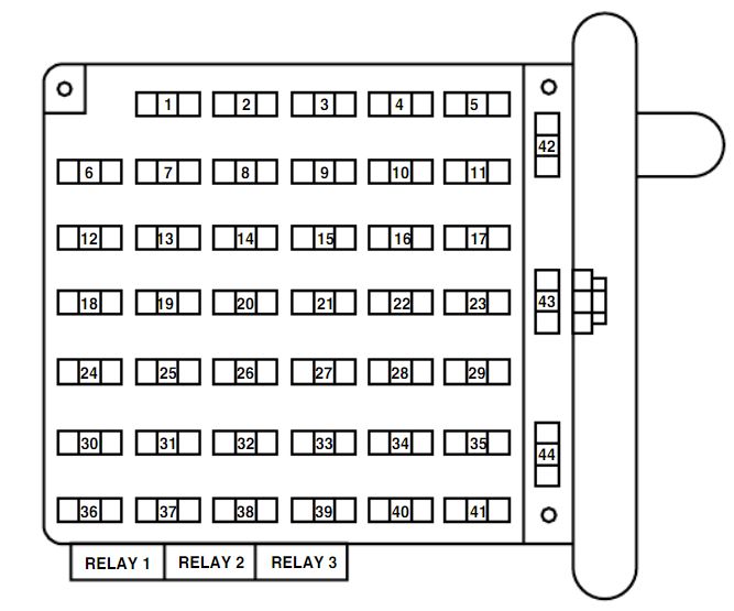
Passenger compartment fuses box
| Fuse/Relay Location | [A] | Description |
| 1 | 20 | Right turn signal relay coil, Left turn signalrelay coil, Right turn indicator, Left turnindicator, Body builder right rear turn/stopfeed, Body builder left rear turn/stop feed |
| 2 | — | — |
| 3 | — | — |
| 4 | 15 | Courtesy lamp relay, Interior lamp feed |
| 5 | 10 | Body builder accessory feed (accessory andrun) |
| 6 | 10 | Trailer tow left stop/turn feed |
| 7 | 15 | Blower motor relay coi |
| 8 | — | — |
| 9 | 20 | Stoplamps: Trailer tow Electric Brakecontroller feed, Body builder right rearturn/stop feed, Body builder left rearturn/stop feed, Body builder stop lamp feed,Trailer left turn/stop fuse feed, Trailer rightturn/stop fuse feed |
| 10 | 5 | Instrument cluster memory, Power BrakeAssist Lamp*Instrument cluster memory, Power BrakeAssist Lamp* |
| 11 | 30 | Wiper/Washer Module, Wiper Feed |
| 12 | 10 | Trailer tow Stop/Turn feed |
| 13 | 10 | ABS Module |
| 14 | 10 | Warning chime module, Power brake assistmodule*, Instrument cluster power,Instrument cluster warning lamps,Transmission control switch |
| 15 | 15 | Left turn signal feed |
| 16 | 20 | Body builder battery (+12V) feed |
| 17 | 5 | Body builder radio feed |
| 18 | — | — |
| 19 | 5 | DRL relays |
| 20 | — | — |
| 21 | 15 | Right turn signal feed |
| 22 | — | — |
| 23 | — | — |
| 24 | — | — |
| 25 | 10 | Right headlamp feed (low beam |
| 26 | 10 | Speed control module, Brake shift interlockactuator |
| 27 | — | — |
| 28 | — | — |
| 29 | — | — |
| 30 | — | — |
| 31 | 10 | Left headlamp feed (low beam) |
| 32 | 10 | Backup lamp feed |
| 33 | — | — |
| 34 | — | — |
| 35 | 20 | Body builder high beam feed, High beamindicator |
| 36 | — | — |
| 37 | — | — |
| 38 | 10 | Body builder accessory feed (run only) |
| 39 | — | — |
| 40 | — | — |
| 41 | 10 | Instrument illumination |
| 42 | — | — |
| 43 | — | — |
| 44 | — | — |
| Relay 1 | — | Left turn signal relay |
| Relay2 | — | Courtesy lamps relay |
| Relay 3 | — | Right turn signal relay |
| *Vehicles with Hydromax brake assist only | ||
Power distribution box
The power distribution box is located in the engine compartment.
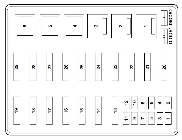
| Fuse/Relay | [A] | Description |
| 1 | 5* | Power Brake Assist Module*** |
| 2 | 10* | A/C System |
| 3 | 20* | 4R100 Transmission, Vapor ManagementValve Solenoid, Heated Exhaust Gas Oxygen(HEGO) Sensors |
| 4 | 5* | Powertrain Control Module Memor |
| 5 | 15* | Powertrain Control Module Power, FuelPump Relay Coil, Fuel Injectors, Mass AirFlow Sensor with IAT, A/C System Relay Coil |
| 6 | 20* | Parklamp Feeds, Instrument Panel Fuse#41, Warning Chime Module, Trailer TowRunning Lamp Relay Coil, I/P DimmerModule |
| 7 | 15* | Starter Relay Coil, BB Neutral Sense |
| 8 | 10* | Stoplamp Switch (Logic): Brake PressureSwitch, Power Brake Assist Module***, Speed Control Module, Powertrain Control Module, ABS module, Brake Shift Interlock Actuator |
| 9 | 5* | Alternator |
| 10 | 20* | Daytime Running (DRL) Lamps |
| 11 | 30* | Ignition Coils, Radio Capacitors #1 and #2,Powertrain Control Module Relay |
| 12 | 20* | Trailer Tow Running Lamps Feed, TrailerTow Backup Lamps Feed, IP-Backup LampFeed |
| 13 | 30** | Trailer Tow Electric Brake Controller Feed |
| 14 | 60** | Instrument Panel Battery Feed (Fuse #9,15, 21) |
| 15 | — | — |
| 16 | 60** | ABS Module |
| 17 | — | — |
| 18 | 20** | Horn Feed |
| 19 | — | — |
| 20 | 40** | Powertrain Control Module Relay |
| 21 | 20** | Fuel Pump Motor |
| 22 | 20** | Diagnostic Tool Connector, Cigar Lighter Feed |
| 23 | 40** | Blower Motor Feed |
| 24 | 40** | Instrument Panel Battery Feed (fuses #4,10, 16) |
| 25 | 50** | Ignition Switch Feed (Instrument PanelFuses #1, 5, 7, 11, 13, 14, 17, 19, PDB fuses#7, 9, 11) |
| 26 | 60** | Ignition Switch Feed (Instrument PanelFuses #5, 11, 17, 26, 32, 38) |
| 27 | 30** | Multifunction Switch (Headlamps) |
| 28 | — | — |
| 29 | 60** | Power Brake Assist Motor*** |
| Relay 1 | — | Daytime Running Lamps On/Off Relay |
| Relay 2 | — | Fuel Pump Relay |
| Relay 3 | — | Horn Relay |
| Relay 4 | — | A/C System Relay |
| Relay 5 | — | Blower Motor Relay |
| Relay 6 | — | Powertrain Control Module Relay |
| Diode 1 | — | Powertrain Control Module Diode |
| Diode 2 | — | Park Brake Diode |
| * Mini Fuses | ||
| ** Maxi Fuses | ||
| ***Vehicles with Hydromax brake assistonly | ||
Relay module
The relay box is located by the power distribution box in front of theradiator in the engine compartment.
| Relay | Description |
| 1 | Back up Lamp |
| 2 | Running Lamp |
| 3 | — |
| 4 | Headlamp DRL |
WARNING: Terminal and harness assignments for individual connectors will vary depending on vehicle equipment level, model, and market.