Hummer H3 (2008 – 2009) – fuse box diagram
Year of production: 2008, 2009
Engine Compartment Fuse Block
The engine compartment fuse block is located on the driver’s side of the engine compartment.
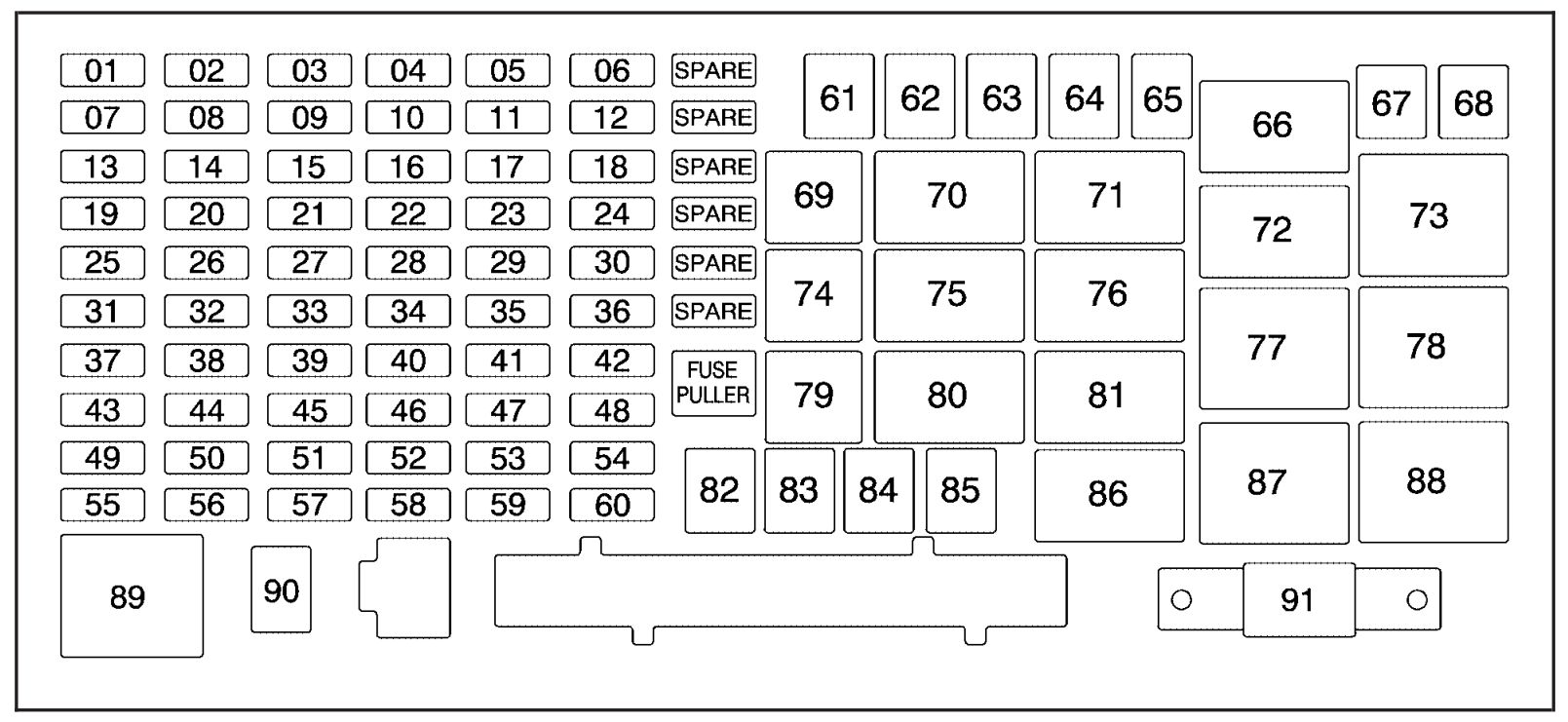
| Fuses | Usage |
| 1 | Heated Seats |
| 2 | Grille Guard |
| 3 | Fuel Pump |
| 4 | Roof Lamp |
| 5 | Battery Ignition Switch |
| 6 | Front Wiper |
| 7 | Regulated Voltage Control Power |
| 8 | Power Locks |
| 9 | Sunroof, Front Washer Pump |
| 10 | Accessories (SPO) |
| 11 | Air Compressor |
| 12 | Transfer Case Control Module |
| 13 | Radio, Heating, Ventilation, Air Conditioning Display |
| 14 | Body Control Module |
| 15 | Rear Wiper Motor |
| 16 | Rear Wiper Pump Switch |
| 17 | Air Injection Reactor (AIR) Solenoid |
| 18 | Spare 6 |
| 19 | Cluster |
| 20 | Rear Turn Signal, Hazard Signal |
| 21 | Powertrain Control Module 1 |
| 22 | Mass Air Flow Sensor, Purge Solenoid |
| 23 | Injector |
| 24 | Fog Lamp |
| 25 | Powertrain Control Module B |
| 26 | Transmission Control Module (TCM) |
| 27 | Airbags |
| 28 | Back-up Lamps |
| 29 | Anti-lock Brakes, StabiliTrak® |
| 30 | Rear Window Defogger |
| 31 | Canister Vent |
| 32 | Regulated Voltage Control VSense+ |
| 33 | Ignition 1 |
| 34 | Transmission |
| 35 | Cruise, Inside Rearview Mirror |
| 36 | Horn |
| 37 | Driver’s Side Rear Park Lamp |
| 38 | Amplifier |
| 39 | Reduced Intensity Low-Beam Daytime Running Lamps |
| 40 | Passenger’s Side Headlamp |
| 41 | Driver’s Side Headlamp |
| 42 | Trailer Back-Up Lamp |
| 43 | Front Park Lamps |
| 44 | Air Injection Reactor (AIR) Solenoid |
| 45 | Auxiliary Power 2 |
| 46 | Electronic Throttle Control |
| 47 | Oxygen Sensor |
| 48 | Air Conditioning Clutch |
| 49 | Passenger’s Side Rear Park Lamp |
| 50 | Spare |
| 51 | Auxiliary Power 1 |
| 52 | StabiliTrak®, Anti-lock Brakes |
| 53 | Power Heater Switch |
| 54 | Stop |
| 55 | Trailer Parking Lamps |
| 56 | Front Turn Signal, Hazard Signal |
| 57 | Power Sunroof |
| 58 | Transfer Case Control Module Switch |
| 59 | Climate Control |
| 60 | Spare 8 |
| 61 | Power Seats |
| 62 | Air Pump |
| 63 | Passenger’s Side Power Window |
| 64 | Anti-lock Brakes, StabiliTrak® 2 Solenoid |
| 67 | Anti-lock Brakes, StabiliTrak® 1 Motor |
| 68 | Driver’s Side Power Window |
| 82 | Climate Control Fan |
| 83 | Electronic Brake Controller |
| 84 | Trailer B+ Fuse |
| 85 | Starter |
| 91 | Megafuse |
| Relay | Usage |
| 66 | Fuel Pump |
| 69 | Fog Lamp |
| 70 | High, Low Beam Headlamps |
| 71 | Rear Defogger |
| 72 | Windshield Wiper On/Off |
| 73 | Windshield Wiper High/Low |
| 74 | Horn |
| 75 | Headlamp |
| 76 | Air Conditioning Clutch |
| 77 | Powertrain Control Module |
| 78 | Run, Crank |
| 79 | Reduced Intensity Low-Beam Daytime Running Lamps |
| 80 | Air Injection Reactor (AIR) Solenoid |
| 81 | Powertrain (Starter) |
| 86 | Spare 2 |
| 87 | Heating, Ventilation, Air Conditioning |
| 88 | Retained Accessory Power |
| 89 | Park Lamp |
| Diode | Usage |
| 65 | Wiper Diode |
| 90 | Air Conditioning Clutch Diode |
WARNING: Terminal and harness assignments for individual connectors will vary depending on vehicle equipment level, model, and market.