Kubota Tractor L3301, L3901 – fuse box diagram
Year of production:
Fuse box
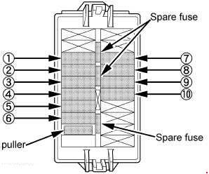
| Number | Ampere ratting [A] | Protected circuit |
| 1 | 5 | Engine ECU (Ignition key) |
| 2 | 5 | Main ECU (Ignition key) |
| 3 | 5 | Meter panel (Ignition key) |
| 4 | 10 | Combination switch |
| 5 | 5 | Work light |
| 6 | 5 | Starter relay |
| 7 | 20 | Engine ECU (Battery) |
| 8 | 5 | Main ECU (Battery) |
| 9 | 5 | Meter panel (Battery) |
| 10 | 10 | Hazard |
Slow blow Fuse
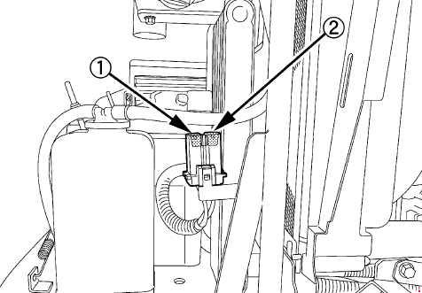
| Number | Ampere ratting [A] | Protected circuit |
| 1 | 40 | LOAD |
| 2 | 50 | BATTERY |
WARNING: Terminal and harness assignments for individual connectors will vary depending on vehicle equipment level, model, and market.