MG MG6 (2014 – 2016) – fuse and relay box diagram
Year of production: 2014, 2015, 2016
This article focuses on the facelifted first-generation MG MG6, produced from 2014 to 2016. It includes fuse box diagrams for the 2014, 2015, and 2016 models, provides information on the locations of the fuse panels inside the vehicle, and outlines the function of each fuse (fuse layout).
Location
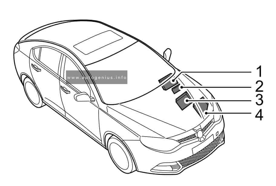
- Passenger Compartment Fuse Box (located behind the glove box)
- Auxiliary Fuse Box (located on the left side of the bulkhead in engine compartment)
- Battery Top Fuse Box (located on the battery)
- Engine Compartment Fuse Box (located in the engine compartment)
Passenger Compartment Fuse Box
Fuse Box Location
The fuse panel is located behind the glove box.
Fuse Box Diagram
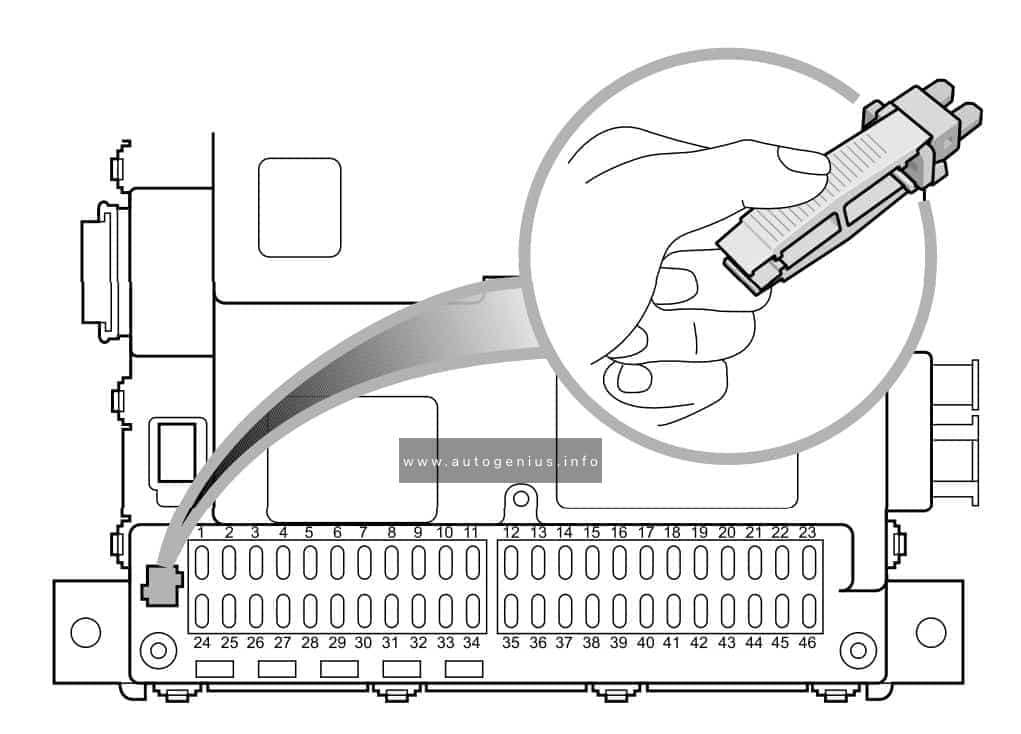
Assignment of the fuses in the passenger compartment
| No. |
А |
Function |
| F1 | 15 | Spare |
| F2 | 15 | Front Power Socket |
| F3 | 10 | Reverse Lamps, Interior Mirror, Camera |
| F4 | 15 | Spare |
| F5 | 5 | Heated Mirror |
| F6 | 10 | Inertia Switch |
| F7 | 15 | Rear Accessory Socket |
| F8 | 30 | Power Supply – Window Lift Front – LH |
| F9 | 5 | Switch – Reverse Lamps, Switch – Master Light, Motor – Headlamp Levelling, AFS System, Passenger Airbag ON/OFF Indicator |
| F10 | 20 | Headlamp Main Beams |
| F11 | — | — |
| FI2 | 5 | Side Lamp – LH, Tail Lamp – LH, Rear Number Plate Lamps |
| F13 | 5 | Switch – EPB |
| F14 | 5 | Switch – Steering Wheel Remote |
| FI5 | 20 | ESCL ECU |
| FI6 | 30 | Pump – Windscreen Wash |
| F17 | 30 | Power Supply – Passenger Seat |
| FI8 | 15 | Horns |
| FI9 | 30 | Heated Seat – Front |
| F20 | 20 | Headlamp Dipped Beam – RH |
| F2I | 30 | Power Supply – Driver Seat |
| F22 | 5 | A/C Control Panel, Heated Seat – Front |
| F23 | 30 | Power Supply – Window Lift Rear – LH |
| F24 | 30 | Power Supply – Window Lift Front – RH |
| F2S | 15 | Spare |
| F26 | 25 | Heater Rear Window |
| F27 | 5 | Switch – Ignition |
| F28 | 5 | Spare |
| F29 | 15 | Spare |
| F30 | 15 | Spare |
| F3I | 25 | Passenger Door Locks, Rear Door Locks |
| F32 | 20 | Headlamp Dipped Beam – LH |
| F33 | — | — |
| F34 | — | — |
| F35 | 10 | Spare |
| F36 | 5 | Side Lamp – RH, Tail Lamp – RH |
| F37 | 5 | Diagnostic Socket |
| F38 | 5 | Lamp – Glovebox |
| F39 | 10 | Driver Door Locks, Motor – Fuel Flap Release, Tailgate Release Motor Relay, Motor – Tailgate Release |
| F40 | 15 | Spare |
| F41 | 10 | Rear Fog Lamps |
| F42 | 10 | Airbag ECU |
| F43 | 20 | Spare |
| F44 | 5 | Interior Mirror, Rain Sensor, PDC ECU |
| F45 | 10 | Multifunction Control Switch, Master Light Switch, Driver Door Switch Pack, Navigation Display Power |
| F46 | 30 | Power Supply – Window Lift Rear – RH |
Engine Compartment Fuse Box
Fuse Box Diagram

Assignment of the fuses in the engine compartment
| No. |
А |
Function |
| F1 | 15 | Sensor – Wide Band, Control Unit – Glow Plug, ECU – Engine, Switch – Clutch Pedal |
| F2 | 20 | Power Supply – Fuel Filter, Bypass – EGR Cooling, Actuator – Variable Swirl, Valve – Throttle Actuator, Sensor – Hot Film Airmass, Variable Geometry Turbo Controller |
| F3 | 10 | Pump – High Pressure, Valve – Pressure Control |
| F4 | 15 | Cooling Fan, Relay – Starter, Relay – Fuel Heater, Master Switch – Start Stop, Relay – Electric Water Heater 1, Relay – Electric Water Heater 3, Switch – Neutral, ECU – Engine |
| F5 | 10 | Spare |
| F6 | 15 | Day Running Lamps |
| F7 | 30 | Lamp – Direction Indicator Front – LH, Lamp – Direction Indicator Rear – LH, Lamp – Side Repeater – LH, Relay – Reverse Lamp, Relay – Position Lamp, Lamp – Rear Brake – LH, Passenger Compartment Fuses 3, 12, 36 |
| F8 | 20 | Passenger Compartment Fuse 7 |
| F9 | 10 | Relay – Compressor Clutch – Air Conditioning, Compressor – Air Conditioning Clutch |
| F10 | 30 | Relay – Wiper 1, Relay – Wiper 2 |
| FL1 | 200 | Alternator, Engine Compartment Fuse Links 2, 7,10 and Fuses 5, 8, 9 |
| FL2 | 60 | Passenger Compartment Fuses 1, 6, 9, 22, 24, 25, 27, 28, 42, Relay – Switched |
| FL3 | 50 | Relay – Horn, Rotary Coupler, Passenger Compartment Fuses 16, 17, 18 |
| FL4 | 50 | Cooling Fan |
| FL5 | 100 | Relay – Dipped Beam, Relay – Rear Fog Lamp, Passenger Compartment Fuses 19, 20, 21, 23, 30, 35, 37, 39, 40, 41, 43, 45, 46 |
| FL6 | 70 | EHPAS ECU & Pump |
| FL7 | 40 | Relay – Starter, Starter Motor |
| FL8 | 40 | SCS ECU (Pump) |
| FL9 | 50 | Passenger Compartment Fuses 2, 5, 10, 13, 14, 15, 26, 38, 44, Relay – Heated Rear Screen, Relay – Main Beam, Relay – Auxiliary |
| FL10 | 40 | Relay – Blower, Motor – Blower, A/C Control Panel |
| FL11 | 25 | SCS ECU (Valve) |
| FL12 | 50 | Relay – Dipped Beam, Lamp – Direction Indicator Front – RH, Lamp – Direction Indicator Rear – RH, Lamp – Side Repeater – RH, Lamps – Rear Brake – RH, Passenger Compartment Fuses 8, 31, 32 |
Auxiliary Fuse Box
Fuse Box Location
It is located on the left side of the bulkhead in engine compartment.
Fuse Box Diagram
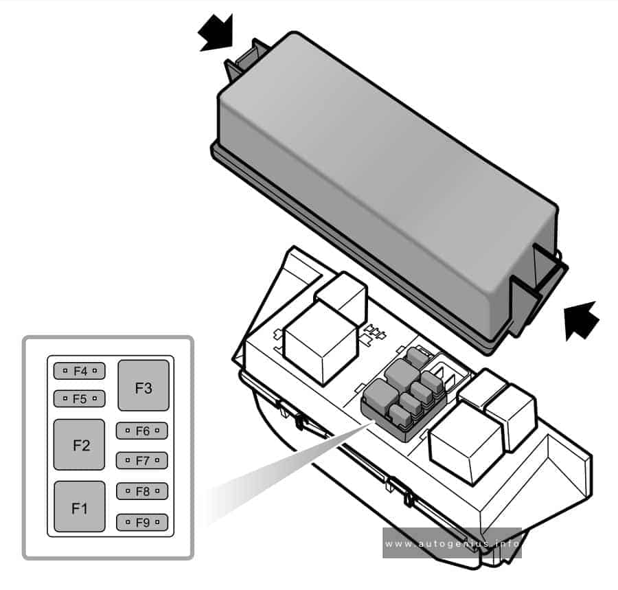
Assignment of the fuses in the auxiliary fuse box
| No. |
А |
Function |
| F1 | 30 | DC/DC Convertor |
| F2 | 30 | Relay – Electric Water Heater 1, Electric Water Heater Element 1 |
| F3 | 30 | Headlamp Wash System |
| F4 | 20 | Relay – Fuel Heater, Fuel Heater |
| F5 | 20 | AFS System |
| F6 | 5 | Interior Lamp – Front, Interior Lamp – Rear, Lamp – Vanity Mirrors |
| F7 | 15 | Entertainment System |
| F8 | 10 | A/C Control Panel, Fresh/Recycle Motor |
| F9 | 10 | Instrument Pack |
Battery Top Fuse Box
Fuse Box Location
The fuse box is located on the battery.
Fuse Box Diagram
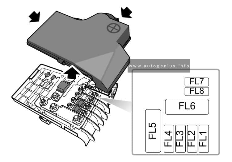
Assignment of the fuses in the battery fuse box.
| No. |
А |
Function |
| FL1 | 30 | EPB ECU |
| FL2 | 30 | EPB ECU |
| FL3 | 125 | Auxiliary Fuses 1, 2, 3, 4, 5, Relay – Electric Water Heater 2, Electric Water Heater Element 2 |
| FL4 | 60 | Control Unit Glow Plug |
| FL5 | — | — |
| FL6 | 450 | Motor – Starter |
| FL7 | 5 | EBS |
| FL8 | 30 | Relay – Electric Water Heater 3, Electric Water Heater Element 3 |
WARNING: Terminal and harness assignments for individual connectors will vary depending on vehicle equipment level, model, and market.