Nio ET7 (2022 – 2024) – fuse and relay box diagram

Nio ET7 (2022 – 2024) – fuse and relay box diagram


Year of production: 2022, 2023, 2024

This article provides fuse box diagrams for the Nio ET7 models from 2022, 2023, and 2024. It includes details on the location of the fuse panels within the vehicle and explains the function and layout of each fuse and relay.


Passenger Compartment Fuse Box

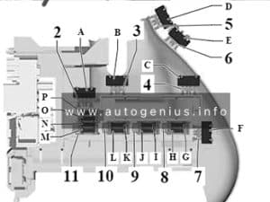
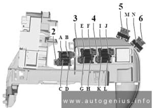
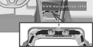
Fuse box location

Nio ET7 (2022 - 2024) - fuse box location - passenger compartment
Nio ET7 (2022 – 2024) – fuse box location – passenger compartment


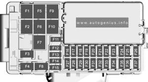
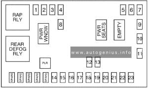
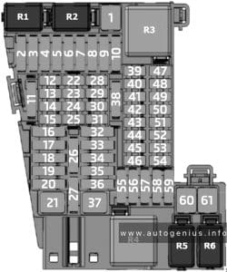
Fuse box diagram

Nio ET7 (2022 - 2024) - fuse box diagram - passenger compartment
Nio ET7 (2022 – 2024) – fuse box diagram – passenger compartment


Assignment of the fuses in the dashboard

Amps Description
IF01 10A Battery management unit (KL30 power supply)
IF02 15A Pyrotechnic safety switch power (KL30 power supply)
IF03 10A Electronic gear selection module (KL30 power supply)
IF04 10A Brake switch (KL30 power supply)
IF05 10A Vehicle controller 1 (KL30 power supply)
IF06 20A Infotainment system console 1 (KL30 power supply)
IF07 10A Body gateway module 1 power supply
IF08 10A Front body control module (safe box) KL30 power supply / wireless charging power supply
IF09 10A Center display power supply
IF10 30A ADAS main controller 1 (KL30 power supply)
IF11 10A Smart antenna power supply
IF12 10A Bluetooth digital key antenna module power supply
IF13 10A Steering column power supply
IF14 10A Heads-up display / smart robot (KL30 power supply)
IF15 10A LiDAR sensor power supply
IF16 30A ADAS main controller 2 (KL30 power supply)
IF17 10A Climate control module (KL30 power supply)
IF18 10A Exterior door handle / driver’s side door control switch power supply
IF19 10A IR01/IR02 relay power supply
IF20 10A Diagnosis interface (KL30 power supply)
IF21 30A Front body controller (exterior light 1) KL30 power supply
IF22 10A ETC (KL30 power supply)
IF23 15A Front body controller (washer pump) KL30 power supply
IF24 10A Rear control panel / rain & light sensor / fragrance control module power supply
IF25 20A Front body control module 1 (KL30 power supply)
IF26 20A Front body control module 2 (KL30 power supply)
IF27 10A Digital instrument cluster (KL30 power supply)
IF28 10A Radar / parking radar controller power supply
IF29 10A Electric power steering power supply 1
IF30 10A Electric power steering power supply 2
IF31 10A Airbag controller (KL15 power supply)
IF32 10A Body controller (KL15 power supply)
IF33 10A Climate control module / ETC / Rearview mirror assembly (KL15 power supply)
IF34 15A Left headlight (KL15 power supply)
IF35 15A Right headlight (KL15 power supply)
IF36 10A Ambient lighting / vanity mirror light / reading light / multi-color footwell light / storage box light (KL15 power supply)
IF37 10A Middle liftgate light (KL15 power supply)
IF38 10A Left body taillight (KL15 power supply)
IF39 10A Right body taillight (KL15 power supply)
IF40 10A Front body controller KL15_1/KL15_2 relay feedback/IR03 relay coil power supply
IF41 25A Front 12V power socket power supply
IF42 10A Safe box USB port power supply
IF43 10A Front body controller power socket relay feedback
IF44 10A Rear control panel USB port (KL15 power supply)
IF45 10A Rear seat USB power supply
IF46 25A Rear 12V power socket power supply
IF47 15A Driver seat pneumatic lumbar support / fan power supply
IF48 15A Passenger seat pneumatic lumbar support / fan power supply
IF49 15A Rear passenger backrest ventilation / massage power supply
IF50 15A (Reserved)
IF51 25A Front body controller (horn) KL30 power supply
IF52 25A Driver seat control power supply
IF53 25A Passenger seat control power supply
IF54 30A Front left door control module KL30 power supply 1
IF55 20A Front left door control module KL30 power supply 2
IF56 30A Front right door control module KL30 power supply 1
IF57 20A Front right door control module KL30 power supply 2
IF58 30A Rear left door control module KL30 power supply 1
IF59 20A Rear left door control module KL30 power supply 2
IF60 30A Rear right door control module KL30 power supply 1
IF61 20A Rear right door control module KL30 power supply 1
IF62 40A Brake pressure regulator motor 2 power supply
IF63 50A IR02 relay switch power supply
IF64 40A IR01 relay switch power supply
IF65 50A IR03 relay switch power supply
IF66 25A (Reserved)
IF67 20A Brake pressure adjustment module power supply
IF68 40A Brake pressure regulator motor 1 power supply
IR01 40A IF29, IF30, IF31, IF32, IF33, IF34, IF35, IF36, IF37, IF38, IF39, IF40 fuse (KL15 power supply)
IR02 70A IF41, IF42, IF43, IF44, IF45, IF46 fuse (KL15 power supply)
IR03 70A IF47, IF48, IF49, IF50 (KL15 power supply)


Engine Compartment Fuse Box

Fuse box location

Nio ET7 (2022 - 2024) - fuse box location - engine compartment
Nio ET7 (2022 – 2024) – fuse box location – engine compartment


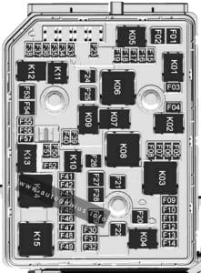
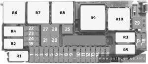
Fuse Box Diagram

Nio ET7 (2022 - 2024) - fuse box diagram - engine compartment
Nio ET7 (2022 – 2024) – fuse box diagram – engine compartment


Assignment of the fuses in the engine compartment fuse box

Amps Description
UF01 60A UR01 relay switch power supply
UF02 (Reserved)
UF03 25A Front body controller (front wiper motor) KL30 power supply
UF04 (Reserved)
UF05 10A High voltage DC converter integrated component
UF06 10A Front inverter (KL30 power supply)
UF07 15A UR02 relay switch power supply
UF08 (Reserved)
UF09 50A UR09 relay switch power supply
UF10 (Reserved)
UF11 20A UR03 relay switch power supply
UF12 10A Electronic shift module (KL87 power supply)
UF13 10A Climate control system / PM2.5 sensor / compressor assembly / heat exchanger electronic expansion valve / heat pump electronic expansion valve (KL87 power supply)
UF14 20A UR07 relay switch power supply
UF15 (Reserved)
UF16 (Reserved)
UF17 10A Rear inverter (KL87 power supply)
UF18 15A Vehicle controller (KL87 power supply)
UF19 (Reserved)
UF20 10A UR01/UR03 relay coil power supply
UF21 10A Five-way cooling water valve (KL87 power supply)
UF22 10A Brake switch (KL87 power supply)
UF23 10A Front bumper movable grille (KL87 power supply)
UF24 (Reserved)
UF25 (Reserved)
UF26 (Reserved)
UF27 (Reserved)
UR01 Cooling fan assembly (KL87 power supply)
UR02 Steering column module (steering wheel heating power supply)
UR03 Electronic water pump – power battery (KL87 power supply)
UR04 UF12, UF13, UF17, UF18, UF20, UF21, UF22, UF23, UF28 fuse power supply
UR05 (Reserved)
UR06 (Reserved)
UR07 Electronic water pump – front motor (KL87 power supply)
UR08 Air supply unit motor power supply
UR09 Front fan (KL87 power supply)
UR10 (Reserved)

Pre-Fuse Box

Fuse box Location
Nio ET7 (2022 - 2024) - fuse box location - engine compartment (pre-fuse box)
Nio ET7 (2022 – 2024) – fuse box location – engine compartment (pre-fuse box)


Fuse box Diagram
Nio ET7 (2022 - 2024) - fuse box diagram - engine compartment (pre-fuse box)
Nio ET7 (2022 – 2024) – fuse box diagram – engine compartment (pre-fuse box)


Fuse Amps Description
DCDC 450A DC/DC converter
UEC POWER 200A Underhood electrical box
IEC POWER 200A Instrument panel fuse box
TEC POWER 200A Trunk Fuse Box
EPS1 POWER 125A Electric power steering gear
EPS2 POWER 125A Electric power steering gear


Luggage Compartment Fuse Box

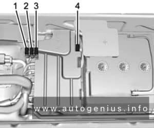
Fuse Box Location

Nio ET7 (2022 - 2024) - fuse box location - luggage compartment
Nio ET7 (2022 – 2024) – fuse box location – luggage compartment


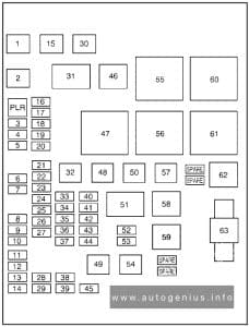
Fuse Box Diagram

Nio ET7 (2022 - 2024) - fuse box diagram - luggage compartment
Nio ET7 (2022 – 2024) – fuse box diagram – luggage compartment


Assignment of the fuses in the luggage compartment

Amps Description
TF01 (Reserved)
TF02 40A IR02 relay switch power supply
TF03 40A IR03 relay switch power supply
TF04 (Reserved)
TF05 30A Liftgate lock power supply
TF06 30A Amplifier control unit power supply 1
TF07 40A Front retractor assembly – left (KL30 power supply)
TF08 10A Rear inverter (KL30 power supply)
TF09 10A Body controller 2 (KL30 power supply)
TF10 10A Battery management unit power supply 1 (KL30)
TF11 20A Infotainment system console (KL30 power supply) 2
TF12 10A Body gateway module power supply 2
TF13 30A ADAS domain controller power supply 2
TF14 30A ADAS domain controller power supply 4
TF15 30A Front body controller (exterior light 2) KL30 power supply
TF16 10A Liftgate kick sensor power supply
TF17 10A Right charging indicator (KL30 power supply)
TF18 (Reserved)
TF19 10A Rear millimeter-wave radar power supply
TF20 (Reserved)
TF21 10A TR02/TR03 relay coil power supply
TF22 (Reserved)
TF23 20A Front body controller (rear seat heating/backlight) KL30 power supply
TF24 20A Flexible chassis controller power supply 3
TF25 20A Flexible chassis controller power supply 4
TF26 (Reserved)
TF27 20A Flexible chassis controller power supply 2
TF28 30A Flexible chassis controller power supply 1
TF29 30A Amplifier control unit power supply 1
TF30 (Reserved)
TF31 (Reserved)
TF32 (Reserved)
TF33 (Reserved)
TF34 (Reserved)
TF35 (Reserved)
TR01 (Reserved)
TR02 Rear defogger power supply
TR03 KL15 power supply (redundancy)
TR04 (Reserved)
TR05 (Reserved)
TR06 (Reserved)


WARNING: Terminal and harness assignments for individual connectors will vary depending on vehicle equipment level, model, and market.

Nio ET5 (2022 – 2024) – fuse and relay box diagram

Nio ET5 (2022 – 2024) – fuse and relay box diagram


Year of production: 2022, 2023, 2024

This article provides fuse box diagrams for the Nio ET5 models from 2022, 2023, and 2024. It includes details on the location of the fuse panels inside the vehicle and offers information on the function and layout of each fuse and relay.


Passenger Compartment Fuse Box

Fuse box location

Nio ET5 (2022) - fuse box location - passenger compartment
Nio ET5 (2022 – 2024) – fuse box location – passenger compartment


Fuse box diagram

Nio ET5 (2022 - 2024) - fuse box diagram - passenger compartment
Nio ET5 (2022 – 2024) – fuse box diagram – passenger compartment


Assignment of the fuses in the dashboard

Amps / Type Description
IF01 50A IR01 relay switch-end power supply
IF02
IF03 20A Brake pressure regulator power supply
IF04 40A Brake pressure regulator motor power supply 1
IF05 40A Brake pressure regulator motor power supply 2
IF06 40A IR03 relay switch-end power supply
IF07 50A IR02 relay switch-end power supply
IF08 10A Driver’s seat lumbar support / fan power supply
IF09 10A Passenger seat lumbar support / fan power supply
IF10 10A Flexible chassis controller power supply 1
IF11
IF12 10A Flexible chassis controller power supply 2
IF13 20A Trailer control module power supply
IF14 10A Body gateway controller
IF15 10A Wireless charging module and body controller (safe box) power supply
IF16 10A Center display power supply
IF17 30A ADAS main controller power supply 1
IF18 10A Smart antennas power supply
IF19 10A Digital key Bluetooth antenna module power supply
IF20 10A Steering column module power supply
IF21 10A Air conditioning control unit power supply
IF22 10A Outer door handle, driver’s door switch power supply
IF23 25A Body controller power supply (rear seats and backlighting)
IF24 10A ETC / alcohol interlock power supply
IF25 10A LiDAR sensor power supply
IF26 15A Body controller power supply (washer fluid pump)
IF27 10A NOMI power supply
IF28 10A Digital instrument cluster display power supply
IF29 10A Diagnostic port power supply
IF30 10A Fragrance module and rain light sensor power supply
IF31 20A Body controller power supply 1
IF32 20A Body controller power supply 2
IF33 ADAS main controller power supply 2
IF34 10A Rear child monitoring / radar sensor / parking radar controller power supply
IF35 10A IR03 relay coil-end power supply
IF36 10A Battery management system power supply
IF37 15A Pyrotechnic cutout switch power supply
IF38 10A Electronic shift module power supply
IF39 10A Brake light switch power supply
IF40 10A Vehicle controller power supply 1
IF41 20A Multimedia system host power supply 1
IF42 25A Front 12V power socket power supply
IF43
IF44 10A Front USB port power supply
IF45 10A Rear control panel USB port power supply
IF46 10A Body gateway controller (power socket relay feedback)
IF47 25A Rear 12V power socket power supply
IF48 15A Body controller power supply (horn)
IF49 30A Driver’s seat control module power supply
IF50 30A Passenger seat control module power supply
IF51 30A Front left door control module power supply 1
IF52 20A Front left door control module power supply 2
IF53 30A Front right door control module power supply 1
IF54 20A Front right door control module power supply 2
IF55 30A Rear left door control module power supply 1
IF56 20A Rear left door control module power supply 2
IF57 30A Rear right door control module power supply 1
IF58 20A Rear right door control module power supply 2
IF59 10A Electric power steering power supply 1
IF60 10A Electric power steering power supply 2
IF61 10A Airbag controller power supply
IF62 10A Body gateway controller / body controller feedback
IF63 10A Air conditioning control unit/ETC/rearview mirror power supply
IF64 20A Left headlight power supply
IF65 20A Right headlight power supply
IF66 10A Liftgate middle taillight power supply
IF67 10A Liftgate left and right taillight power supply
IF68 10A Vehicle controller power supply
IF69 10A Interior lighting
IF70 10A Four-door speaker ambient lighting power supply
IR01 MINI Power socket relay
IR02 MINI Seat / flexible chassis control relay
IR03 ISO MINI KL15 relay


Engine Compartment Fuse Box

Fuse box location

Nio ET5 (2022 - 2024) - fuse box location - engine compartment
Nio ET5 (2022 – 2024) – fuse box location – engine compartment


Fuse Box Diagram

Nio ET5 (2022 - 2024) - fuse box diagram - engine compartment
Nio ET5 (2022 – 2024) – fuse box diagram – engine compartment


Assignment of the fuses in the engine compartment fuse box

Amps / Type Description
UF01 60A UR01 relay switch-end power supply
UF02
UF03 25A Front body controller (front wiper motor) KL30 power supply
UF04
UF05 10A High-voltage DC converter integrated component
UF06 10A Front inverter (KL30 power supply)
UF07
UF08
UF09 50A UR09 relay switch-end power supply
UF10
UF11 20A UR03 relay switch-end power supply
UF12 10A Electronic shift module (KL87 power supply)
UF13 10A Climate control system / PM2.5 sensor / compressor assembly / heat exchanger electronic expansion valve / heat pump electronic expansion valve (KL87 power supply)
UF14 20A UR07 relay switch-end power supply
UF15
UF16
UF17 10A Rear HV power distribution unit (KL87 power supply)
UF18 15A Vehicle controller (KL87 power supply)
UF19
UF20 10A UR01/UR03 relay coil-end power supply
UF21 10A Five-way cooling water valve (KL87 power supply)
UF22 10A Brake switch (KL87 power supply)
UF23 10A Front bumper movable grille (KL87 power supply)
UF24
UF25
UF26 15A Front windshield heating
UF27
UF28 10A UR07 relay coil-end power supply
UR01 MINI Cooling fan relay
UR02
UR03 280 MICRO High-voltage battery electronic water pump relay
UR04 ISO MINI Main relay
UR05
UR06 Front windshield heating relay
UR07 280 MICRO Front motor electronic water pump relay
UR08
UR09 MINI Front fan relay

Pre-Fuse Box

Fuse box Location
Nio ET5 (2022 - 2024) - fuse box location - engine compartment (pre-fuse box)
Nio ET5 (2022 – 2024) – fuse box location – engine compartment (pre-fuse box)


Fuse box Diagram
Nio ET5 (2022 - 2024) - fuse box diagram - engine compartment (pre-fuse box)
Nio ET5 (2022 – 2024) – fuse box diagram – engine compartment (pre-fuse box)


Amps Description
PF01 450A DC/DC converter
PF02 200A Front trunk fuse box
PF03 200A Instrument panel fuse box
PF04 200A Rear trunk fuse box
PF05 125A Electric power steering gear power supply 2
PF06 125A Electric power steering gear power supply 1


Luggage Compartment Fuse Box

Fuse Box Location

Nio ET5 (2022 - 2024) - fuse box location - luggage compartment
Nio ET5 (2022 – 2024) – fuse box location – luggage compartment


Fuse Box Diagram

Nio ET5 (2022 - 2024) - fuse box diagram - luggage compartment
Nio ET5 (2022 – 2024) – fuse box diagram – luggage compartment


Assignment of the fuses in the luggage compartment

Amps / Type Description
TF01
TF02 40A TR02 relay switch-end power supply
TF03 40A TR03 relay switch-end power supply
TF04 20A Trailer control module power supply 1
TF05 30A Liftgate control module power supply
TF06 30A Power amplifier control unit power supply 1
TF07
TF08 10A Rear inverter power supply
TF09 10A Vehicle controller power supply 2
TF10 10A Battery management unit power supply 1
TF11 20A Multimedia system host power supply 2
TF12 10A Body gateway controller power supply 2
TF13 30A ADAS main controller power supply 2
TF14 30A ADAS main controller power supply 4
TF15 30A Body controller KL30 power supply (exterior lighting 2)
TF16 10A Liftgate kick sensor power supply
TF17 10A Charging indicator power supply
TF18 30A Body controller KL30 power supply (exterior lighting 1)
TF19
TF20 20A Trailer control module power supply 2
TF21 10A TR02 relay coil-end power supply
TF22 10A Onboard charging module power supply (charging communication)
TF23 10A Onboard charging module power supply
TF24 40A Front row left retractor assembly power supply
TF25
TF26
TF27 30A Flexible chassis controller power supply 2
TF28 30A Flexible chassis controller power supply 1
TF29 30A Power amplifier control unit power supply 2
TF30 10A Charge port ground reverse protection A-
TF31 10A Charging confirmation signal A+
TF32
TF33
TF34
TF35
TR01
TR02 ISO MINI Rear defog relay
TR03 ISO MINI KL15 power supply relay (redundant)
TR04
TR05
TR06


WARNING: Terminal and harness assignments for individual connectors will vary depending on vehicle equipment level, model, and market.

Nio ES8 (2020 – 2023) – fuse and relay box diagram

Nio ES8 (2020 – 2023) – fuse and relay box diagram


Year of production: 2020, 2021, 2022, 2023

This article provides fuse box diagrams for the Nio EL8 / Nio ES8 models from 2020 to 2023. You will also discover the location of the fuse panels within the vehicle and find details about the fuse and relay assignments (fuse layout).


Passenger Compartment Fuse Box

Fuse box diagram and Location

Nio ES8 (2020 - 2023) - fuse box diagram - passenger compartment
Nio ES8 (2020 – 2023) – fuse box diagram – passenger compartment

Assignment of the fuses in the dashboard

Amps Description
1 IF02 / IF29 / IF26 fuse (KL15 power supply) relay
2 (Reserved) relay
3 TR03 relay power supply / TR06 relay coil / IF01 / IF25 / IF27 / IF30 / IF43 / TF01 / TF25 fuse (KL15 power supply) relay
4 (Reserved)
5 (Reserved)
6 10A Brake booster / electric power steering-1 (KL15 power supply) fuse
7 15A Driver seat heating / ventilation / lumbar support / massage module (KL15 power supply) fuse
8 10A KL15-Trailer
9 10A Electric parking controller / electric power steering-2 (KL15 power supply) fuse
10 10A IR04 relay (coil) / right front headlight / rear-view mirror assembly / left front headlight (KL15 power supply) fuse
11 15A Passenger side heating / ventilation/lumbar support / massage module (KL15 power supply) fuse
12 10A Airbag controller (KL15 power supply) fuse
13 10A Radar / parking radar controller / central gateway controller (KL15 power supply) fuse
14 15A Steering wheel heating (KL15 power supply) fuse
15 10A Climate control module / front body controller / central gatewaycontroller / vehicle controller / ECALL / DAB box / DAB adaptor (KL15 power supply) / side mirrormemory feedback + fuse
16 (Reserved)
17 (Reserved)
18 30A Electric parking controller 1 (KL30 power supply)
19 (Reserved)
20 25A IR02 relay power supply fuse
21 (Reserved)
22 25A Front body controller (front wipers) KL30 power supply fuse
23 40A Sunroof / sunshade motor (KL30 power supply) fuse
24 IF28 fuse (KL15 power supply) relay
25 (Reserved)
26 30A Front body control module 1 fuse
27 30A Front body control module 2 fuse
28 10A Digital instrument cluster / HUD / NOMI / eCall (KL30 power supply) fuse
29 10A Climate control module / rear climate control panel and fragrance system (KL30 power supply) fuse
30 10A Body control module (safe box lock power supply) /DAB box fuse
31 10A Steering column power supply fuse
32 10A Brake switch (KL30 power supply) fuse
33 10A Driver’s side door control switch / rain sensor / wireless charging power supply (models with air suspension) fuse
34 20A Infotainment system console (KL30 power supply) 1 fuse
35 10A Body controller (KL30 power supply) fuse
36 30A IR04 relay switch power supply fuse
37 (Reserved)
38 (Reserved)
39 60A Brake booster fuse
40 30A Electric parking controller 2 (KL30 power supply)
41 Left side mirror left adjustment relay
42 10A Climate control module (KL30 power supply) fuse
43 20A Battery management unit (KL30 power supply) fuse
44 10A Center display (KL30 power supply) fuse
45 10A Electronic gear selector module (KL30 power supply) fuse
46 30A Front body control module (central lock) fuse
47 10A IR06 / IR08 / IR09 relay fuse
48 10A ADAS main controller (KL30 power supply) fuse
49 10A Diagnosis interface (KL30 power supply) fuse
50 10A IR10 / IR11 / IR12 relay fuse
51 10A IR07 / IR13 relay fuse
52 15A IR05 power supply fuse
53 10A Central gateway controller (KL30 power supply) fuse
54 Side mirror unfold relay
55 (Reserved)
56 Left side mirror right/upward adjustment relay
57 Left side mirror downward adjustment relay
58 Right side mirror left adjustment relay
59 Right side mirror right/upward adjustment relay
60 Right side mirror downward adjustment relay
61 Side mirror fold relay


Engine Compartment Fuse Box

Fuse Box Diagram and Location

Nio ES8 (2020 - 2023) - fuse box diagram - engine compartment
Nio ES8 (2020 – 2023) – fuse box diagram – engine compartment

Assignment of the fuses in the engine compartment fuse box

Amps Description
1 60A UR06 relay power supply fuse
2 10A High voltage integrated component
3 20A Washer pump fuse
4 15A UR05 relay power supply fuse
5 10A Vehicle communication controller / high voltage charging indicator fuse
6 15A UR04 relay power supply fuse
7 (Reserved)
8 (Reserved)
9 15A UR07 relay power supply fuse
10 Front motor cooling water pump relay
11 Rear motor cooling water pump relay
12 Battery cooling water pump relay
13 Cooling fan relay
14 (Reserved)
15 40A Brake control module (control unit) fuse
16 40A Brake control module (motor) fuse
17 (Reserved)
18 15A Vehicle controller (KL87) fuse
19 10A Climate control system fuse
20 10A UR04 coil / UR05 coil / UR06 coil / UR07 coil / fan / brake switch / active grille shutter / high voltage battery pack heating / three-way valve / four-way valve fuse
21 10A Left high beam fuse
22 10A Right high beam fuse
23 10A ADAS main controller power supply 2 fuse
24 15A UR08 relay power supply fuse
25 10A Left low beam fuse
26 20A Battery management system power supply fuse
27 15A Front power control unit fuse
28 10A Central gateway controller power supply 2 fuse
29 10A Right low beam fuse
30 Right low beam relay
31 Left low beam relay
32 Horn relay
33 High beam relay
34 10A High voltage power distribution box / gear shifter module fuse
35 (Reserved)
36 Main relay
37 (Reserved)

Luggage Compartment Fuse Box

Fuse Box Diagram and Location

Nio ES8 (2020 - 2023) - fuse box diagram - luggage compartment
Nio ES8 (2020 – 2023) – fuse box diagram – luggage compartment

Assignment of the fuses in the luggage compartment

Amps Description
1 TF02/TF27 fuse power supply relay
2 KL15 power supply
3 Rear blower (KL30 power supply) relay
4 Front blower (KL30 power supply) relay
5 (Reserved)
6 10A Wheel arch light / ambient lighting / safe box limit switch fuse
7 15A Left front and rear exterior door handle deploy + / retract – fuse
8 15A Left front and rear exterior door handle deploy – / retract + fuse
9 15A Right front and rear exterior door handle deploy – / retract + fuse
10 10A Liftgate taillight / body taillight / sunroof switch / vanity mirror light / puddle light fuse
11 10A USB hub (KL15 power supply) fuse
12 15A Right front and rear exterior door handle deploy + /retract – fuse
13 10A Right side mirror heating fuse
14 10A Left side mirror heating fuse
15 10A Second row seat USB fuse
16 (Reserved)
17 (Reserved)
18 25A Left front / right rear window regulator motor (KL30 power supply) fuse
19 60A TR01 relay contactor power supply fuse
20 30A Passenger seat adjustment fuse
21 30A Driver seat adjustment fuse
22 40A Air suspension controller (air pump) KL30 power supply fuse
23 30A Liftgate control module (motor) fuse
24 TF42/TF43 fuse power supply
25 (Reserved)
26 20A Air suspension controller (KL30 power supply) fuse
27 15A CC2 charge port motor power supply fuse
28 15A TR07 relay power supply fuse
29 10A Rear inverter (KL30 power supply) fuse
30 10A Liftgate control module fuse
31 20A Infotainment system console (KL30 power supply) 2 fuse
32 30A TR04 relay switch power supply fuse
33 30A TR05 relay switch power supply fuse
34 30A Rear body controller power supply 1 fuse
35 10A Kick sensor / TR04 coil / TR05 coil / TR08 coil / TR09 coil / TR11 coil fuse
36 30A Amplifier control unit fuse
37 25A TR03 relay power supply fuse
38 40A TR11 relay contactor power supply fuse
39 30A TR02 relay contactor power supply fuse
40 25A Right-front / left-rear window regulator motor (KL30) fuse
41 Second row seat heating relay
42 10A Vehicle controller power supply fuse
43 15A Rear wiper fuse
44 15A TR10 relay / TR12 relay fuse
45 30A Rear body controller power supply 2 fuse
46 25A TR06 relay contactor power supply fuse
47 25A TR08 relay contactor power supply fuse
48 25A TR09 relay contactor power supply fuse
49 (Reserved)
50 10A TR13 relay fuse
51 20A Trailer control module power1
52 20A Trailer control module power2
53 (Reserved)
54 TF29 / TF28 fuse power supply
55 (Reserved)
56 TF26 fuse / TF30 fuse / front 12V power socket power supply
57 Rear 12V power socket
58 Second row left seat easy entry relay
59 Rear defogger relay
60 Second row right seat easy entry relay
61 Liftgate lock relay


Pre-Fuse Box

Fuse Box Diagram
Nio ES8 (2020 - 2023) - fuse box diagram - engine compartment (pre-fuse box)
Nio ES8 (2020 – 2023) – fuse box diagram – engine compartment (pre-fuse box)
Amps Description
1 30A Pyrotechnic safety switch power supply
2 125A Electric power steering gear power supply
3 300A DC/DC converter power supply
4 200A Trunk fuse box power supply
5 125A Instrument panel electrical box power supply
6 125A Underhood electrical box power supply


WARNING: Terminal and harness assignments for individual connectors will vary depending on vehicle equipment level, model, and market.

Nio EL (2020 – 2023) – fuse and relay box diagram

Nio EL8 (2020 – 2023) – fuse and relay box diagram


Year of production: 2020, 2021, 2022, 2023

This article provides fuse box diagrams for the Nio EL8 / Nio ES8 models from 2020 to 2023. You will also discover the location of the fuse panels within the vehicle and find details about the fuse and relay assignments (fuse layout).


Passenger Compartment Fuse Box

Fuse box diagram

Nio EL8 (2020 - 2023) - fuse box diagram - passenger compartment
Nio EL8 (2020 – 2023) – fuse box diagram – passenger compartment

Assignment of the fuses in the dashboard

Amps Description
1 IF02 / IF29 / IF26 fuse (KL15 power supply) relay
2 (Reserved) relay
3 TR03 relay power supply / TR06 relay coil / IF01 / IF25 / IF27 / IF30 / IF43 / TF01 / TF25 fuse (KL15 power supply) relay
4 (Reserved)
5 (Reserved)
6 10A Brake booster / electric power steering-1 (KL15 power supply) fuse
7 15A Driver seat heating / ventilation / lumbar support / massage module (KL15 power supply) fuse
8 10A KL15-Trailer
9 10A Electric parking controller / electric power steering-2 (KL15 power supply) fuse
10 10A IR04 relay (coil) / right front headlight / rear-view mirror assembly / left front headlight (KL15 power supply) fuse
11 15A Passenger side heating / ventilation/lumbar support / massage module (KL15 power supply) fuse
12 10A Airbag controller (KL15 power supply) fuse
13 10A Radar / parking radar controller / central gateway controller (KL15 power supply) fuse
14 15A Steering wheel heating (KL15 power supply) fuse
15 10A Climate control module / front body controller / central gatewaycontroller / vehicle controller / ECALL / DAB box / DAB adaptor (KL15 power supply) / side mirrormemory feedback + fuse
16 (Reserved)
17 (Reserved)
18 30A Electric parking controller 1 (KL30 power supply)
19 (Reserved)
20 25A IR02 relay power supply fuse
21 (Reserved)
22 25A Front body controller (front wipers) KL30 power supply fuse
23 40A Sunroof / sunshade motor (KL30 power supply) fuse
24 IF28 fuse (KL15 power supply) relay
25 (Reserved)
26 30A Front body control module 1 fuse
27 30A Front body control module 2 fuse
28 10A Digital instrument cluster / HUD / NOMI / eCall (KL30 power supply) fuse
29 10A Climate control module / rear climate control panel and fragrance system (KL30 power supply) fuse
30 10A Body control module (safe box lock power supply) /DAB box fuse
31 10A Steering column power supply fuse
32 10A Brake switch (KL30 power supply) fuse
33 10A Driver’s side door control switch / rain sensor / wireless charging power supply (models with air suspension) fuse
34 20A Infotainment system console (KL30 power supply) 1 fuse
35 10A Body controller (KL30 power supply) fuse
36 30A IR04 relay switch power supply fuse
37 (Reserved)
38 (Reserved)
39 60A Brake booster fuse
40 30A Electric parking controller 2 (KL30 power supply)
41 Left side mirror left adjustment relay
42 10A Climate control module (KL30 power supply) fuse
43 20A Battery management unit (KL30 power supply) fuse
44 10A Center display (KL30 power supply) fuse
45 10A Electronic gear selector module (KL30 power supply) fuse
46 30A Front body control module (central lock) fuse
47 10A IR06 / IR08 / IR09 relay fuse
48 10A ADAS main controller (KL30 power supply) fuse
49 10A Diagnosis interface (KL30 power supply) fuse
50 10A IR10 / IR11 / IR12 relay fuse
51 10A IR07 / IR13 relay fuse
52 15A IR05 power supply fuse
53 10A Central gateway controller (KL30 power supply) fuse
54 Side mirror unfold relay
55 (Reserved)
56 Left side mirror right/upward adjustment relay
57 Left side mirror downward adjustment relay
58 Right side mirror left adjustment relay
59 Right side mirror right/upward adjustment relay
60 Right side mirror downward adjustment relay
61 Side mirror fold relay


Engine Compartment Fuse Box

Fuse Box Diagram

Nio EL8 (2020 - 2023) - fuse box diagram - engine compartment
Nio EL8 (2020 – 2023) – fuse box diagram – engine compartment

Assignment of the fuses in the engine compartment fuse box

Amps Description
1 60A UR06 relay power supply fuse
2 10A High voltage integrated component
3 20A Washer pump fuse
4 15A UR05 relay power supply fuse
5 10A Vehicle communication controller / high voltage charging indicator fuse
6 15A UR04 relay power supply fuse
7 (Reserved)
8 (Reserved)
9 15A UR07 relay power supply fuse
10 Front motor cooling water pump relay
11 Rear motor cooling water pump relay
12 Battery cooling water pump relay
13 Cooling fan relay
14 (Reserved)
15 40A Brake control module (control unit) fuse
16 40A Brake control module (motor) fuse
17 (Reserved)
18 15A Vehicle controller (KL87) fuse
19 10A Climate control system fuse
20 10A UR04 coil / UR05 coil / UR06 coil / UR07 coil / fan / brake switch / active grille shutter / high voltage battery pack heating / three-way valve / four-way valve fuse
21 10A Left high beam fuse
22 10A Right high beam fuse
23 10A ADAS main controller power supply 2 fuse
24 15A UR08 relay power supply fuse
25 10A Left low beam fuse
26 20A Battery management system power supply fuse
27 15A Front power control unit fuse
28 10A Central gateway controller power supply 2 fuse
29 10A Right low beam fuse
30 Right low beam relay
31 Left low beam relay
32 Horn relay
33 High beam relay
34 10A High voltage power distribution box / gear shifter module fuse
35 (Reserved)
36 Main relay
37 (Reserved)

Luggage Compartment Fuse Box

Fuse Box Diagram

Nio EL8 (2020 - 2023) - fuse box diagram - luggage compartment
Nio EL8 (2020 – 2023) – fuse box diagram – luggage compartment

Assignment of the fuses in the luggage compartment

Amps Description
1 TF02/TF27 fuse power supply relay
2 KL15 power supply
3 Rear blower (KL30 power supply) relay
4 Front blower (KL30 power supply) relay
5 (Reserved)
6 10A Wheel arch light / ambient lighting / safe box limit switch fuse
7 15A Left front and rear exterior door handle deploy + / retract – fuse
8 15A Left front and rear exterior door handle deploy – / retract + fuse
9 15A Right front and rear exterior door handle deploy – / retract + fuse
10 10A Liftgate taillight / body taillight / sunroof switch / vanity mirror light / puddle light fuse
11 10A USB hub (KL15 power supply) fuse
12 15A Right front and rear exterior door handle deploy + /retract – fuse
13 10A Right side mirror heating fuse
14 10A Left side mirror heating fuse
15 10A Second row seat USB fuse
16 (Reserved)
17 (Reserved)
18 25A Left front / right rear window regulator motor (KL30 power supply) fuse
19 60A TR01 relay contactor power supply fuse
20 30A Passenger seat adjustment fuse
21 30A Driver seat adjustment fuse
22 40A Air suspension controller (air pump) KL30 power supply fuse
23 30A Liftgate control module (motor) fuse
24 TF42/TF43 fuse power supply
25 (Reserved)
26 20A Air suspension controller (KL30 power supply) fuse
27 15A CC2 charge port motor power supply fuse
28 15A TR07 relay power supply fuse
29 10A Rear inverter (KL30 power supply) fuse
30 10A Liftgate control module fuse
31 20A Infotainment system console (KL30 power supply) 2 fuse
32 30A TR04 relay switch power supply fuse
33 30A TR05 relay switch power supply fuse
34 30A Rear body controller power supply 1 fuse
35 10A Kick sensor / TR04 coil / TR05 coil / TR08 coil / TR09 coil / TR11 coil fuse
36 30A Amplifier control unit fuse
37 25A TR03 relay power supply fuse
38 40A TR11 relay contactor power supply fuse
39 30A TR02 relay contactor power supply fuse
40 25A Right-front / left-rear window regulator motor (KL30) fuse
41 Second row seat heating relay
42 10A Vehicle controller power supply fuse
43 15A Rear wiper fuse
44 15A TR10 relay / TR12 relay fuse
45 30A Rear body controller power supply 2 fuse
46 25A TR06 relay contactor power supply fuse
47 25A TR08 relay contactor power supply fuse
48 25A TR09 relay contactor power supply fuse
49 (Reserved)
50 10A TR13 relay fuse
51 20A Trailer control module power1
52 20A Trailer control module power2
53 (Reserved)
54 TF29 / TF28 fuse power supply
55 (Reserved)
56 TF26 fuse / TF30 fuse / front 12V power socket power supply
57 Rear 12V power socket
58 Second row left seat easy entry relay
59 Rear defogger relay
60 Second row right seat easy entry relay
61 Liftgate lock relay


Pre-Fuse Box

Fuse Box Diagram
Nio EL8 (2020 - 2023) - fuse box diagram - engine compartment (pre-fuse box)
Nio EL8 (2020 – 2023) – fuse box diagram – engine compartment (pre-fuse box)
Amps Description
1 30A Pyrotechnic safety switch power supply
2 125A Electric power steering gear power supply
3 300A DC/DC converter power supply
4 200A Trunk fuse box power supply
5 125A Instrument panel electrical box power supply
6 125A Underhood electrical box power supply


WARNING: Terminal and harness assignments for individual connectors will vary depending on vehicle equipment level, model, and market.

Nio ES7 (2022 – 2024) – fuse and relay box diagram

Nio ES7 (2022 – 2024) – fuse and relay box diagram


Year of production: 2022, 2023, 2024

This article provides fuse box diagrams for the Nio EL7 model from 2022, 2023, and 2024. It also includes details on the location of the fuse panels within the vehicle and explains the function of each fuse (fuse layout) and relay.


Passenger Compartment Fuse Box

Fuse box location

Nio ES7 (2022 - 2024) - fuse box location - passenger compartment
Nio ES7 (2022 – 2024) – fuse box location – passenger compartment


Fuse box diagram

Nio EL7 (2022 - 2024) - fuse box diagram - passenger compartment
Nio EL7 (2022 – 2024) – fuse box diagram – passenger compartment


Assignment of the fuses in the dashboard

Amps Description
IF01 10A Battery management unit (KL30 power supply)
IF02 20A Rear feature island (KL30 power supply)
IF03 10A Electronic gear selection module (KL30 power supply)
IF04 10A Brake switch (KL30 power supply)
IF05 10A Vehicle controller 1 (KL30 power supply)
IF06 20A Infotainment system console 1 (KL30 power supply)
IF07 10A Body gateway module 1 power supply
IF08 10A Front body control module (safe box) KL30 power supply/wireless charging power supply
IF09 10A Center display power supply
IF10 30A ADAS main controller 1 (KL30 power supply)
IF11 10A Smart antenna power supply
IF12 10A Bluetooth digital key antenna module power supply
IF13 10A Steering column power supply
IF14 10A Heads-up display / smart robot (KL30 power supply)
IF15 10A LiDAR sensor power supply
IF16 30A ADAS main controller 2 (KL30 power supply)
IF17 10A Climate control module (KL30 power supply)
IF18 10A Exterior door handle / driver door control switch power supply
IF19 10A IR01/IR02 relay power supply
IF20 10A Diagnosis interface (KL30 power supply)
IF21 20A Body controller (seat heating and backlight) KL30 power supply
IF22 10A ETC (KL30 power supply)
IF23 15A Body controller (washer pump) KL30 power supply
IF24 10A Climate control module / rain & light sensor / fragrance control module power supply
IF25 20A Body control module 1 (KL30 power supply)
IF26 20A Body control module 2 (KL30 power supply)
IF27 10A Digital instrument cluster (KL30 power supply)
IF28 10A Radar/parking radar controller power supply
IF29 10A Electric power steering power supply 1
IF30 10A Electric power steering power supply 2
IF31 10A Airbag controller (KL15 power supply)
IF32 10A Body controller (KL15 power supply)
IF33 10A Climate control module / ETC / Rearview mirror assembly (KL15 power supply)
IF34 15A Left headlight (KL15 power supply)
IF35 15A Right headlight (KL15 power supply)
IF36 10A Ambient lighting / vanity mirror light / reading light / multi-color footwell light / storage box light (KL15 power supply)
IF37 15A Middle tailgate light (KL15 power supply)
IF38 10A Left body taillight (KL15 power supply)
IF39 10A Right body taillight (KL15 power supply)
IF40 10A Front body controller KL15_1 / KL15_2 relay feedback / IR03 relay coil power supply
IF41 25A Front 12V power socket power supply
IF42 10A Safe box USB port power supply
IF43 10A Front body controller power socket relay feedback
IF44 10A Rear control panel USB port 1 (KL15 power supply)
IF45 10A Rear seat USB power supply
IF46 25A Rear 12V power socket power supply
IF47 10A Driver seat pneumatic lumbar support power supply
IF48 10A Passenger seat pneumatic lumbar support power supply
IF49 10A Rear passenger massage power supply
IF50 15A (Reserved)
IF51 15A Body controller (charging) KL30 power supply
IF52 30A Driver seat control power supply
IF53 30A Passenger seat control power supply
IF54 30A Front left door control module KL30 power supply 1
IF55 20A Front left door control module KL30 power supply 2
IF56 30A Front right door control module KL30 power supply 1
IF57 20A Front right door control module KL30 power supply 2
IF58 30A Rear left door control module KL30 power supply 1
IF59 20A Rear left door control module KL30 power supply 2
IF60 30A Rear right door control module KL30 power supply 1
IF61 20A Rear right door control module KL30 power supply 1
IF62 40A Brake pressure regulator motor 2 power supply
IF63 50A IR02 relay switch power supply
IF64 40A IR01 relay switch power supply
IF65 50A IR03 relay switch power supply
IF66 40A Sunroof power supply
IF67 20A Brake pressure adjustment module power supply
IF68 40A Brake pressure regulator motor 1 power supply
IR01 40A IF29, IF30, IF31, IF32, IF33, IF34, IF35, IF36, IF37, IF38, IF39, IF40 fuse (KL15 power supply)
IR02 70A 1F41, IF42, IF43, IF44, IF45, IF46 fuse (KL15 power supply)
IR03 70A IF47, IF48, IF49, IF50 (KL15 power supply)


Engine Compartment Fuse Box

Fuse box location

Nio ES7 (2022 - 2024) - fuse box location - engine compartment
Nio ES7 (2022 – 2024) – fuse box location – engine compartment


Fuse Box Diagram

Nio ES7 (2022 - 2024) - fuse box diagram - engine compartment
Nio ES7 (2022 – 2024) – fuse box diagram – engine compartment


Assignment of the fuses in the engine compartment fuse box

Amps Description
UF01 60A UR01 relay switch power supply
UF02 40A Active seat belt power supply
UF03 25A Body controller (front wiper motor) KL30 power supply
UF04 (Reserved)
UF05 10A High voltage DC converter integrated component power supply
UF06 10A Front inverter (KL30 power supply)
UF07 15A UR02 relay switch power supply
UF08 10A Charge port indicator power supply
UF09 50A UR09 relay switch power supply
UF10 (Reserved)
UF11 20A UR03 relay switch power supply
UF12 10A Electronic shift module (KL87 power supply)
UF13 10A Climate control system/UR09 relay coil power supply
UF14 20A UR07 relay switch power supply
UF15 40A UR08 relay switch power supply
UF16 (Reserved)
UF17 10A High-voltage power distributer power supply
UF18 15A Vehicle controller (KL87 power supply)
UF19 (Reserved)
UF20 10A UR01 / UR03 relay coil power supply
UF21 10A Five-way cooling water valve (KL87 power supply)
UF22 10A Brake switch (KL87 power supply)
UF23 10A Front bumper movable grille (KL87 power supply)
UF24 15A Horn power supply
UF25 (Reserved)
UF26 (Reserved)
UF27 (Reserved)
UF28 10A UR07 relay coil power supply
UR01 Cooling fan assembly (KL87 power supply)
UR02 Steering column module (steering wheel heating power supply)
UR03 Electric water pump – power battery (KL87 power supply)
UR04 UF12, UF13, UF17, UF18, UF20, UF21, UF22, UF23, UF28 fuse power supply
UR05 Horn power supply
UR06 (Reserved)
UR07 Electric water pump – front motor (KL87 power supply)
UR08 Air supply unit motor power supply
UR09 Front fan (KL87 power supply)

Luggage Compartment Fuse Box

Fuse Box Location

Nio ES7 (2022 - 2024) - fuse box location - luggage compartment
Nio ES7 (2022 – 2024) – fuse box location – luggage compartment


Fuse Box Diagram

Nio ES7 (2022 - 2024) - fuse box diagram - luggage compartment
Nio ES7 (2022 – 2024) – fuse box diagram – luggage compartment


Assignment of the fuses in the luggage compartment

Amps Description
TF01 (Reserved)
TF02 (Reserved)
TF03 10A Battery management unit power supply 1 (KL30)
TF04 10A Body gateway module 2 power supply
TF05 15A Rear wiper (KL30) power supply
TF06 10A Rear inverter power supply
TF07 10A LiDAR sensor power supply
TF08 30A ADAS controller 1 power supply
TF09 (Reserved)
TFIO 30A ADAS domain controller power supply 2
TF11 30A Body controller (exterior lighting power supply) 1
TF12 30A Body controller (exterior lighting power supply) 2
TF13 10A Body controller power supply 2
TF14 10A TR02 relay coil power supply
TF15 10A Tailgate kick sensor power supply
TF16 20A Infotainment system console (KL30 power supply) 2
TF17 15A Pyrotechnic safety switch power supply
TF18 (Reserved)
TF19 10A TR03 relay coil power supply
TF20 (Reserved)
TF21 (Reserved)
TF22 (Reserved)
TF23 (Reserved)
TF24 (Reserved)
TF25 (Reserved)
TF26 (Reserved)
TF27 (Reserved)
TF28 (Reserved)
TF29 (Reserved)
TF30 (Reserved)
TF31 20A Flexible chassis controller power supply 4
TF32 30A Rear seat power supply
TF33 30A Amplifier control unit power supply 1
TF34 30A Tailgate motor power supply
TF35 (Reserved)
TF36 30A Amplifier control unit power supply 2
TF37 30A Flexible chassis controller power supply 1
TF38 20A Flexible chassis controller power supply 2
TF39 40A Rear defogger power supply
TF40 40A TR03 relay switch power supply
TF41 20A Flexible chassis controller power supply 3
TR01 (Reserved)
TR02 40A Rear defogger power supply
TR03 40A KL15 power supply (redundancy)
TR04 (Reserved)
TR05 (Reserved)
TR06 (Reserved)
TR07 30A Rear wiper power supply
TR08 (Reserved)
TR09 (Reserved)
TR10 (Reserved)
TR11 (Reserved)
TR12 (Reserved)
TR13 (Reserved)


Pre-Fuse Box

Fuse Box Location

Nio ES7 (2022 - 2024) - fuse box location - pre-fuse box
Nio ES7 (2022 – 2024) – fuse box location – pre-fuse box


Fuse Box Diagram

Nio ES7 (2022 - 2024) - fuse box diagram - pre-fuse box
Nio ES7 (2022 – 2024) – fuse box diagram – pre-fuse box


Amps Description
PF01 450A DC/DC converter
PF02 200A Underhood electrical box
PF03 200A Instrument panel fuse box
PF04 200A Trunk Fuse Box
PF05 125A Electric power steering gear
PF06 125A Electric power steering gear


WARNING: Terminal and harness assignments for individual connectors will vary depending on vehicle equipment level, model, and market.

Nio ES6 (2024) – fuse and relay box diagram

Nio ES6 (2024) – fuse and relay box diagram


Year of production: 2024

This article provides fuse box diagrams for the 2024 Nio EL6 / ES6, details the location of the fuse panels within the vehicle, and explains the function and layout of each fuse and relay.


Passenger Compartment Fuse Box

Fuse box location

Nio ES6 (2024) - fuse box location - passenger compartment
Nio ES6 (2024) – fuse box location – passenger compartment

Fuse box diagram

Nio ES6 (2024) - fuse box diagram - passenger compartment
Nio ES6 (2024) – fuse box diagram – passenger compartment


Assignment of the fuses in the dashboard

Amps / Type Description
IF01 10A Battery management unit
IF02 15A Pyrotechnic safety switch
IF03 10A Electronic gear shift module
IF04 10A Brake light switch
IF05 10A Vehicle controller 1
IF06 10A Central computing cluster 1 (multimedia)
IF07 7.5A Body gateway controller 1
IF08 7.5A Driver’s seat control module / passenger seat control module / safe box lock
IF09 10A Center display
IF10 30A Central computing cluster (ADAS controller standby power supply 1)
IF11 10A Smart antenna
IF12 7.5A Digital key Bluetooth antenna module
IF13 10A Steering column module
IF14 10A Air conditioning control unit
IF15 10A Exterior door handle / front-left door control switch
IF16 10A Body controller 1 (backlight)
IF17 7.5A Child detection/wireless charging/ETC
IF18 10A LiDAR sensor
IF19 15A Body controller (washing pump)
IF20 10A Head-up display / intelligent robot / alcohol interlock (EU)
IF21 7.5A Digital instrument cluster display
IF22 10A Data diagnosis interface
IF23 7.5A Rear function console / fragrance module / rain and light sensor
IF24 20A Body controller 1
IF25 20A Body controller 2
IF26 30A Central computing cluster (ADAS controller standby power supply 2)
IF27 10A Parking radar controller/radar sensor
IF28 10A IR01 relay coil / IR02 relay coil / TR04 relay coil power supply
IF29 10A Electric power steering power supply 1
IF30 10A Electric power steering power supply 2
IF31 10A Airbag controller
IF32 7.5A BCM/CGW feedback signal
IF33 10A Air conditioning control unit / ETC / rearview mirror
IF34 20A Left headlight
IF35 20A Right headlight
IF36 10A Liftgate side tail lights
IF37 10A Body left tail light / body right tail light
IF38 10A Vehicle control unit
IF39 10A Ambient lighting / vanity mirror lighting / reading lights / multi-color floor lights / glove box lights (KL15 power supply)
IF40 Reserved
IF41 25A Front 12V power socket
IF42 25A Rear USB port
IF43 10A First-row USB
IF44 10A Rear control panel USB port
IF45 7.5A Power socket relay feedback signal
IF46 10A Rear seat USB/rear panel USB
IF47 10A Driver’s seat massage
IF48 10A Passenger seat message
IF49 10A Lumbar support for rear passengers
IF50 20A Towing control module
IF51 15A Body controller (steering wheel and horn)
IF52 30A Driver’s seat control power supply
IF53 30A Passenger seat control power supply
IF54 30A Front-left door control module 1
IF55 20A Front-left door control module 2
IF56 30A Front-right door control module 1
IF57 20A Front-right door control module 2
IF58 30A Rear-left door control module 1
IF59 20A Rear-left door control module 2
IF60 30A Rear-right door control module 1
IF61 20A Rear-right door control module 2
IF62 30A Driver’s seat control unit 2
IF63 25A TR04 relay switch power supply
IF64 40A Sunroof motor
IF65 30A Passenger seat control unit 2
IF66 50A IR02 relay switch power supply
IF67 40A IR01 relay switch power supply
IF68 50A IR03 relay switch power supply
IR01 MINI KL15 relay
IR02 POWER MINI Power socket relay
IR03 POWER MINI Seat/towing control relay


Engine Compartment Fuse Box

Fuse box location

Nio ES6 (2024) - fuse box location - engine compartment
Nio ES6 (2024) – fuse box location – engine compartment


Fuse Box Diagram

Nio ES6 (2024) - fuse box diagram - engine compartment
Nio ES6 (2024) – fuse box diagram – engine compartment


Assignment of the fuses in the engine compartment fuse box

Amps / Type Description
UF01
UF02 60A Brake pressure regulator motor 2
UF03 20A UR06 relay switch power supply
UF04 60A Brake pressure regulator motor 1
UF05 20A UR02 relay switch power supply
UF06 50A UR03 relay switch power supply
UF07 30A Front wiper motor
UF08 60A UR05 relay switch power supply
UF09 10A UR01 relay coil power supply
UF10 10A High-voltage DC converter integrated component
UF11
UF12 10A Front inverter
UF13
UF14
UF15 10A Air conditioning related
UF16
UF17 10A Rear high-voltage power distribution unit / High-voltage integrated module
UF18 15A Vehicle controller
UF19
UF20 10A Cooling fan / front cooling water pump battery relay coil power supply
UF21 10A Five-way cooling water valve
UF22 10A Brake switch
UF23 10A Front bumper movable grille
UF24 10A Cooling water pump relay coil power supply
UF25 125A Electric power steering gear_2
UF26 125A Electric power steering gear_1
UF27 200A Rear trunk fuse box
UF28 200A Instrument panel fuse box
UF29 400A High-voltage DC converter integrated component
UR01 MICRO Main relay power supply
UR02 MICRO Electronic water pump – high-voltage battery power supply
UR03 POWER MINI Front fan power supply
UR04 POWER MINI Spare fuse box
UR05 POWER MINI Cooling fan power supply
UR06 MICRO Electronic water pump – motor power supply
UR07 MICRO

Luggage Compartment Fuse Box

Fuse Box Location

Nio ES6 (2024) - fuse box location - luggage compartment
Nio ES6 (2024) – fuse box location – luggage compartment


Fuse Box Diagram

Nio ES6 (2024) - fuse box diagram - luggage compartment
Nio ES6 (2024) – fuse box diagram – luggage compartment


Assignment of the fuses in the luggage compartment

S/N Amps / Type Description
TF01 30A Rear seat control unit 1
TF02 40A TR02 relay switch control
TF03 40A TR03 relay switch power supply
TF04 20A Trailer control module power supply 1
TF05 30A Liftgate control module
TF06 30A Power amplifier control unit 1
TF07 30A Rear seat control unit 2
TF08 10A Rear inverter
TF09 10A Vehicle control unit 2
TF10 10A Battery management system 1
TF11 10A Central computing cluster (entertainment power supply 2)
TF12 7.5A Body gateway controller – 2
TF13 30A Central computing cluster (ADAS main power supply 2)
TF14 30A Central computing cluster (ADAS master power supply 1)
TF15 30A Body controller 2 (exterior lighting)
TF16 10A Liftgate kick-activated sensor
TF17 7.5A Charging indicator light – right / rear seat / XR BOX
TF18 30A Body controller 1 (exterior lighting)
TF19 15A TR06 relay power supply
TF20 20A Trailer control module power supply 2
TF21 10A Rear defogging coil control
TF22 10A Charging communication
TF23 10A Onboard charging module
TF24 40A Front row retractor assembly power supply
TF25 30A Flexible chassis controller power supply 1
TF26 20A Flexible chassis controller power supply 2
TF27 20A Flexible chassis controller power supply 4
TF28 20A Flexible chassis controller power supply 3
TF29 30A Power amplifier control unit 2
TF30 10A DC charge port ground
TF31 10A DC charge port power supply
TF32 15A Rear seat USB
TF33 10A USB DP IN port
TR01 POWER MINI Reserved
TR02 MINI Rear defogging
TR03 MINI KL15 power supply (redundant)
TR04 MICRO USB 3.0 port control
TR05 MICRO Reserved
TR06 MICRO Rear wipers


WARNING: Terminal and harness assignments for individual connectors will vary depending on vehicle equipment level, model, and market.

Nio EL6 (2024) – fuse and relay box diagram

Nio EL6 (2024) – fuse and relay box diagram


Year of production: 2024

This article provides fuse box diagrams for the 2024 Nio EL6 / ES6, details the location of the fuse panels within the vehicle, and explains the function and layout of each fuse and relay.


Passenger Compartment Fuse Box

Fuse box location

Nio EL6 (2024) - fuse box location - passenger compartment
Nio EL6 (2024) – fuse box location – passenger compartment

Fuse box diagram

Nio EL6 (2024) - fuse box diagram - passenger compartment
Nio EL6 (2024) – fuse box diagram – passenger compartment


Assignment of the fuses in the dashboard

Amps / Type Description
IF01 10A Battery management unit
IF02 15A Pyrotechnic safety switch
IF03 10A Electronic gear shift module
IF04 10A Brake light switch
IF05 10A Vehicle controller 1
IF06 10A Central computing cluster 1 (multimedia)
IF07 7.5A Body gateway controller 1
IF08 7.5A Driver’s seat control module / passenger seat control module / safe box lock
IF09 10A Center display
IF10 30A Central computing cluster (ADAS controller standby power supply 1)
IF11 10A Smart antenna
IF12 7.5A Digital key Bluetooth antenna module
IF13 10A Steering column module
IF14 10A Air conditioning control unit
IF15 10A Exterior door handle / front-left door control switch
IF16 10A Body controller 1 (backlight)
IF17 7.5A Child detection/wireless charging/ETC
IF18 10A LiDAR sensor
IF19 15A Body controller (washing pump)
IF20 10A Head-up display / intelligent robot / alcohol interlock (EU)
IF21 7.5A Digital instrument cluster display
IF22 10A Data diagnosis interface
IF23 7.5A Rear function console / fragrance module / rain and light sensor
IF24 20A Body controller 1
IF25 20A Body controller 2
IF26 30A Central computing cluster (ADAS controller standby power supply 2)
IF27 10A Parking radar controller/radar sensor
IF28 10A IR01 relay coil / IR02 relay coil / TR04 relay coil power supply
IF29 10A Electric power steering power supply 1
IF30 10A Electric power steering power supply 2
IF31 10A Airbag controller
IF32 7.5A BCM/CGW feedback signal
IF33 10A Air conditioning control unit / ETC / rearview mirror
IF34 20A Left headlight
IF35 20A Right headlight
IF36 10A Liftgate side tail lights
IF37 10A Body left tail light / body right tail light
IF38 10A Vehicle control unit
IF39 10A Ambient lighting / vanity mirror lighting / reading lights / multi-color floor lights / glove box lights (KL15 power supply)
IF40 Reserved
IF41 25A Front 12V power socket
IF42 25A Rear USB port
IF43 10A First-row USB
IF44 10A Rear control panel USB port
IF45 7.5A Power socket relay feedback signal
IF46 10A Rear seat USB/rear panel USB
IF47 10A Driver’s seat massage
IF48 10A Passenger seat message
IF49 10A Lumbar support for rear passengers
IF50 20A Towing control module
IF51 15A Body controller (steering wheel and horn)
IF52 30A Driver’s seat control power supply
IF53 30A Passenger seat control power supply
IF54 30A Front-left door control module 1
IF55 20A Front-left door control module 2
IF56 30A Front-right door control module 1
IF57 20A Front-right door control module 2
IF58 30A Rear-left door control module 1
IF59 20A Rear-left door control module 2
IF60 30A Rear-right door control module 1
IF61 20A Rear-right door control module 2
IF62 30A Driver’s seat control unit 2
IF63 25A TR04 relay switch power supply
IF64 40A Sunroof motor
IF65 30A Passenger seat control unit 2
IF66 50A IR02 relay switch power supply
IF67 40A IR01 relay switch power supply
IF68 50A IR03 relay switch power supply
IR01 MINI KL15 relay
IR02 POWER MINI Power socket relay
IR03 POWER MINI Seat/towing control relay


Engine Compartment Fuse Box

Fuse box location

Nio EL6 (2024) - fuse box location - engine compartment
Nio EL6 (2024) – fuse box location – engine compartment


Fuse Box Diagram

Nio EL6 (2024) - fuse box diagram - engine compartment
Nio EL6 (2024) – fuse box diagram – engine compartment


Assignment of the fuses in the engine compartment fuse box

Amps / Type Description
UF01
UF02 60A Brake pressure regulator motor 2
UF03 20A UR06 relay switch power supply
UF04 60A Brake pressure regulator motor 1
UF05 20A UR02 relay switch power supply
UF06 50A UR03 relay switch power supply
UF07 30A Front wiper motor
UF08 60A UR05 relay switch power supply
UF09 10A UR01 relay coil power supply
UF10 10A High-voltage DC converter integrated component
UF11
UF12 10A Front inverter
UF13
UF14
UF15 10A Air conditioning related
UF16
UF17 10A Rear high-voltage power distribution unit / High-voltage integrated module
UF18 15A Vehicle controller
UF19
UF20 10A Cooling fan / front cooling water pump battery relay coil power supply
UF21 10A Five-way cooling water valve
UF22 10A Brake switch
UF23 10A Front bumper movable grille
UF24 10A Cooling water pump relay coil power supply
UF25 125A Electric power steering gear_2
UF26 125A Electric power steering gear_1
UF27 200A Rear trunk fuse box
UF28 200A Instrument panel fuse box
UF29 400A High-voltage DC converter integrated component
UR01 MICRO Main relay power supply
UR02 MICRO Electronic water pump – high-voltage battery power supply
UR03 POWER MINI Front fan power supply
UR04 POWER MINI Spare fuse box
UR05 POWER MINI Cooling fan power supply
UR06 MICRO Electronic water pump – motor power supply
UR07 MICRO

Luggage Compartment Fuse Box

Fuse Box Location

Nio EL6 (2024) - fuse box location - luggage compartment
Nio EL6 (2024) – fuse box location – luggage compartment


Fuse Box Diagram

Nio EL6 (2024) - fuse box diagram - luggage compartment
Nio EL6 (2024) – fuse box diagram – luggage compartment


Assignment of the fuses in the luggage compartment

S/N Amps / Type Description
TF01 30A Rear seat control unit 1
TF02 40A TR02 relay switch control
TF03 40A TR03 relay switch power supply
TF04 20A Trailer control module power supply 1
TF05 30A Liftgate control module
TF06 30A Power amplifier control unit 1
TF07 30A Rear seat control unit 2
TF08 10A Rear inverter
TF09 10A Vehicle control unit 2
TF10 10A Battery management system 1
TF11 10A Central computing cluster (entertainment power supply 2)
TF12 7.5A Body gateway controller – 2
TF13 30A Central computing cluster (ADAS main power supply 2)
TF14 30A Central computing cluster (ADAS master power supply 1)
TF15 30A Body controller 2 (exterior lighting)
TF16 10A Liftgate kick-activated sensor
TF17 7.5A Charging indicator light – right / rear seat / XR BOX
TF18 30A Body controller 1 (exterior lighting)
TF19 15A TR06 relay power supply
TF20 20A Trailer control module power supply 2
TF21 10A Rear defogging coil control
TF22 10A Charging communication
TF23 10A Onboard charging module
TF24 40A Front row retractor assembly power supply
TF25 30A Flexible chassis controller power supply 1
TF26 20A Flexible chassis controller power supply 2
TF27 20A Flexible chassis controller power supply 4
TF28 20A Flexible chassis controller power supply 3
TF29 30A Power amplifier control unit 2
TF30 10A DC charge port ground
TF31 10A DC charge port power supply
TF32 15A Rear seat USB
TF33 10A USB DP IN port
TR01 POWER MINI Reserved
TR02 MINI Rear defogging
TR03 MINI KL15 power supply (redundant)
TR04 MICRO USB 3.0 port control
TR05 MICRO Reserved
TR06 MICRO Rear wipers


WARNING: Terminal and harness assignments for individual connectors will vary depending on vehicle equipment level, model, and market.

Volkswagen ID.7 (2023 – 2024) – fuse and relay box diagram

Volkswagen ID.7 (2023 – 2024) – fuse and relay box diagram


Year of production: 2021, 2022, 2023, 2024


The Volkswagen ID.7, a battery-electric executive liftback, has been available since 2023. This article provides fuse box diagrams for the 2023 and 2024 Volkswagen ID.7 models, along with details on the fuse panel locations within the vehicle and the specific functions of each fuse and relay (fuse layout).


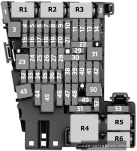
Passenger Compartment Fuse Box

Fuse box location

Left-hand drive vehicle: Reach behind the cover and pull off in the direction of the arrow.

Volkswagen ID.7 (2023 - 2024) - fuse box location - passenger compartment (LHD)
Volkswagen ID.7 (2023 – 2024) – fuse box location – passenger compartment (LHD)


Right-hand drive vehicle: Open the glove box and empty if necessary; reach behind the cover from the side and pull it

Volkswagen ID.7 (2023 - 2024) - fuse box location - passenger compartment (RHD)
Volkswagen ID.7 (2023 – 2024) – fuse box location – passenger compartment (RHD)

Fuse box diagram (Fuse Panel C -SC-)

Volkswagen ID.7 (2023 - 2024) - fuse box diagram - passenger compartment (fuse panel C -SC-)
Volkswagen ID.7 (2023 – 2024) – fuse box diagram – passenger compartment (fuse panel C -SC-)

Assignment of the fuses in the instrument panel fuse box

Amps Function / component
F1
F2 15A Airbag control unit
F3 25A Trailer detector control unit
F4 7.5A Front camera for driver assist systems
F5 25A Onboard supply control unit
F6 30A Onboard supply control unit
F7 30A Heater and air conditioning system control unit
F8 10A Control unit 1 for electrically variable glass
Roof system control unit
F9 30A Driver door control unit (LHD)
Front passenger door control unit (RHD)
Rear driver side door control unit (LHD)
Rear passenger side door control unit (RHD)
F10 5A Left tail light cluster
Centre tail light cluster
F11 15A Trailer detector control unit
F12
F13 40A Onboard supply control unit
F14 40A Digital sound package control unit
F15
F16
F17 5A Parking aid control unit
Lane change assist control unit
Lane change assist control unit 2
F18 5A Entry and start authorisation control unit
Control unit for electronic steering column lock
Rear lid power opening control unit
Control unit 2 for break-in protection
Control unit 3 for break-in protection
Control unit 4 for break-in protection
Control unit 5 for break-in protection
F19 5A Navigation system interface
Control unit with display unit for driver information system
F20 7.5A Charging unit 1 for mobile devices
Aerial amplifier for mobile telephone
USB connection 1
F21 7.5A Control unit for overhead view camera
F22 5A Engine/motor control unit
F23 5A Internet access control unit
F24 5A Right tail light cluster
Centre tail light cluster
F25 25A Front left seat belt
F26 30A Driver door control unit (RHD)
Front passenger door control unit (LHD)
Rear driver side door control unit (RHD)
Rear passenger side door control unit (LHD)
F27 25A Front right seat belt
F28 10A Battery regulation control unit
Maintenance connector for high-voltage system
Cable coil for emergency services cut-out connection
F29 15A Trailer detector control unit
F30 25A Control unit 1 for information electronics
F31 25A Trailer detector control unit
F32 25A Onboard supply control unit
F33
F34 15A Heater and air conditioning system control unit
F35 40A Operating and display unit for rear air conditioning system
F36
F37 30A Rear lid control unit
F38 5A Valve block 1 in driver seat
Valve block 2 in driver seat
Valve block 1 in front passenger seat
Valve block 2 in front passenger seat
F39 10A Steering column electronics control unit
F40 7.5A Alarm horn
F41 5A Data bus diagnostic interface
F42
F43 1A Operating and display unit for rear air conditioning system
Sensor for interior carbon dioxide concentration
Vehicle interior temperature sensor
Heated rear window relay
F44 7.5A Hazard warning light switch
Rain and light sensor
Anti-theft alarm sensor
Centre switch module in dash panei
Operating unit for window regulator in driver door
Operating unit for lighting
Dynamic light strip 3 for information
Diagnostic connection
Front roof module
F45 5A Steering column electronics control unit
F46 7.5A Display unit for front information display and operating unit control unit
Control unit for Head-up Display
F47 7.5A Electronically controlled damping control unit
F48
F49
F50
F51
F52 15A 12 V Socket 3
F53
F54
F55
F56
F57
F58 7.5A Front right seat backrest fan 1
Front right seat cushion fan 1
Front right seat depth adjustment fan
F59 7.5A Relay for power sockets
Automatic anti-dazzle interior mirror
F60 10A Diagnostic connection
F61 5A Power and control electronics for electric drive
F62
F63 7.5A Front left seat backrest fan 1
Front left seat cushion fan 1
Front left seat depth adjustment fan
F64
F65
F66
F67 25A Frequency modulation (FM) frequency filter in positive wire
A Driver seat adjustment thermal fuse 1
B Front passenger seat adjustment thermal fuse 1
R1 Power sockets relay
R2 Terminal 15 voltage supply relay
R3 Heated rear window relay


Front Compartment Fuse Box

Fuse box location

Press the locking button in the direction of the arrow (arrows) in order to unlock the cover of the fuse box.

Volkswagen ID.7 (2023 - 2024) - fuse box location - engine compartment
Volkswagen ID.7 (2023 – 2024) – fuse box location – engine compartment


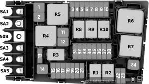
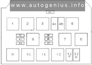
Fuse Box Diagram (Fuse panel B -SB-)

Volkswagen ID.7 (2023 - 2024) - fuse box diagram - engine compartment (fuse panel B -SB-)
Volkswagen ID.7 (2023 – 2024) – fuse box diagram – engine compartment (fuse panel B -SB-)


Assignment of the fuses in the front compartment fuse box

Amps Function / component
F1
F2 7.5A ABS control unit
F3 15A Voltage converter
Charging unit 1 for high-voltage battery
Power and control electronics for electric drive
F4 30A Front left headlight
F5 30A Front right headlight
F6 5A Adaptive cruise control unit
F7 30A Front passenger side windscreen wiper motor
F8 30A Fresh air blower control unit
F9 15A Horn or dual tone horn
Horn relay
Onboard supply control unit
F10 30A Driver side windscreen wiper motor
F11 7.5A Air conditioning System relay
F12 7.5A Engine sound generator module 1
F13 25A ABS control unit
F14
F15 40A ABS control unit
F16 50A Radiator fan
F17 30A Heated windscreen
F18 30A Heated windscreen
F19
F20
F21
F22
F23 5A Engine/motor control unit
F24 5A Radiator fan
F25 15A Coolant pump for high-voltage battery
PTC heater element 3
F26 15A Coolant pump for low-temperature circuit
Control motor for radiator roller blind
F27
F28
F29
F30
F31
F32 50A Brake servo
R1 Control motor for radiator roller blind
R2 Control motor for radiator roller blind
R3 Control motor for radiator roller blind
R4
R5
R6 Control motor for radiator roller blind

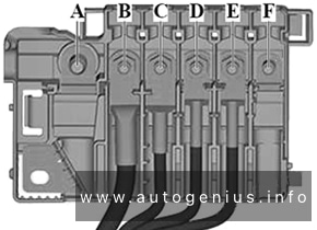
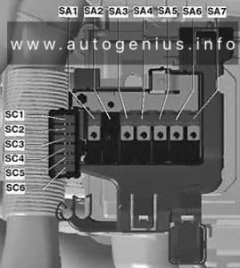
High power fuses (Fuse panel A -SA-)
Volkswagen ID.7 (2023 - 2024) - fuse box diagram - engine compartment (high power fuses (Fuse panel A -SA-))
Volkswagen ID.7 (2023 – 2024) – fuse box diagram – engine compartment (high power fuses (Fuse panel A -SA-))


Assignment of the fuses in the front compartment fuse box

Amps Function / component
508 Battery (Threaded connection (30), on E-box)
SA1 350A Voltage converter
SA2 80A Battery monitor control unit
Power steering control unit
SA3 100A Fuse holder C (Instrument Panel)
SA4 100A Fuse holder C (Instrument Panel)
SA5
SA6 125A Fuse holder B (Front Compartment)


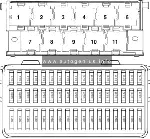
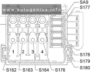
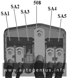
WARNING: Terminal and harness assignments for individual connectors will vary depending on vehicle equipment level, model, and market.

Chrysler Pacifica (2021 – 2024) – fuse box diagram

Chrysler Pacifica (2021 – 2024) – fuse box diagram

Year of production: 2021, 2022, 2023, 2024


The Chrysler Pacifica minivan (RU, facelifted) has been available from 2021 to the present. In this article, you’ll find fuse box diagrams for the 2021, 2022, 2023, and 2024 models, along with details on the location of the fuse panels within the vehicle and the function of each fuse (fuse layout).

Engine Compartment Fuse Box

Fuse box location

The Power Distribution Center (PDC) is situated in the engine compartment, close to the battery. To remove the cover, simply release the two latches on either side of the PDC cover. Avoid using screwdrivers or other tools, as they may exert too much force and cause damage or breakage. Once the service is complete, ensure the cover is securely fastened with the two latches.

A label identifying each component is printed on the inside of the cover.

Chrysler Pacifica (2021 - 2024) - fuse box location - engine compartment
Chrysler Pacifica (2021 – 2024) – fuse box location – engine compartment

Fuse box diagram

Chrysler Pacifica (2021 - 2024) - fuse box diagram - engine compartment
Chrysler Pacifica (2021 – 2024) – fuse box diagram – engine compartment

Assignment of the fuses in the engine compartment (2021-2024)

Amps Description
F06 Not Used
F07 25A Clear Ignition Coil / Fuel Injector
F08 Not Used
F09 25A Clear Amplifier / Active Noise Control
F10 Not Used
F11 Not Used
F12 5A Tan Battery Sensor (IBS)
F13 10A Red ECM (S)
F14 10A Red ECM
F15 40A Green CBC / Power Locks
F16 20A Yellow ECM
F17 30A Pink Starter
F18 40A Green CBC / EXT LIGHTS
F19 25A Clear 2nd Row Folding Seats Solenoid (Left)
F20 10A Red A/C Compressor Clutch
F21 25A Clear 2nd Row Folding Seat Solenoid (Right)
F22 Not Used
F23 Not used
F24 20A Yellow RR Wiper
F25 10A Red Hands Free Dr Mod / Active Grille Shutter / Pwr Mirror / VRM
F26 40A Green Front HVAC Blower Motor
F27 25A Clear RR Slide Door Module – Right
F28 10A Red Diagnostic Port / USB+(IP) / Video USB Port / Overhead DVD Player (Aftermarket)
F29 Not Used
F30 15A Blue Media HUB/ Power Lumbar
F31 Not Used
F32 20A Blue ECM
F33 30A Pink Power Liftgate Module
F34 25A Clear RR Door Module – Left
F35 25A Clear Sunroof
F36 Not Used
F37 40A Green CBC / Exterior Lights
F38 60A Yellow Vacuum Cleaner
F39 25A Clear Rear HVAC Blower Motor
F40 Not Used
F41 Not Used
F42 40A Green Folding Seat Module
F43 20A Yellow Fuel Pump Motor
F44 30A Pink CBC / Interior Lights
F45 30A Pink Power Inverter
F46 30A Pink Driver Door Module
F47 30A Pink Passenger Door Module
F48 Not Used
F49 25A Clear RR Sliding Door Module – Left
F50 25A Clear RR Door Module – Right
F51 30A Pink Front Wiper
F52 30A Pink Brake Vacuum Pump
F53 Not Used
F54 40A Green ESP-ECU And Valves
F55 15A Blue Radio Frequency HUB / Keyless Ignition System (KIN) / ESL / DVD
F56 10A Red Front and Rear HVAC Control Module / Occupant Classification Module (OCM) / Electronic Steering Lock (ESL) / ESP / ESC
F57 Not Used
F58 10A Red Drive Train Control Mod / Power Transfer Unit
F59 30A Pink Trailer Tow Receptacle
F60 20A Yellow Rear Cargo Pwr Outlet
F61 20A Yellow Trailer Tow Right Stop/Turn
F62 20A Yellow Power Transfer Unit
F63 20A Yellow Trailer Tow Left Stop/Turn
F64 15A Blue HID Headlamp (Right)
F65 Not Used
F66 15A Blue Cluster
F67 10A Red Haptic Lane Feedback Module (HALF) / Parktronics System (PTS) / Drivers Assist System Module (DASM)
F68 Not Used
F69 Not Used
F70 Not Used
F71 20A Yellow Horn
F72 10A Red Heated Mirror
F73 30A Pink Rear Defroster
F74 20A Blue Trailer Tow Backup Lights
F75 5A Tan Overhead Console / RR Center Stack
F76 20A Yellow Uconnect / Center Display / Telematics
F77 10A Red RR Entertainment / Media HUB / USB (S) / Rain Sensor/ Sunroof / RR View Mirror / Overhead DVD Player / INT Monitoring Camera / Wireless Charging Pad
F78 15A Blue TCM (ZF) / E-Shifter / Cluster
F79 10A Red ICS / HVAC / SCCM/ EPB SW
F80 Not Used
F81 Not Used
F82 Not Used
F83 20A Blue TT Park Lights
F83 30A Pink Headlamp Washer Pump
F84 30A Pink Drive Train Control MOD
F85 20A Yellow Cigar Lighter
F86 Not Used
F87 Not Used
F88 20A Yellow Front Heated Seats
F89 20A Yellow Rear Heated Seats
F90 Not Used
F91 15A Blue Front Ventilated Seats / Heated Steering Wheel
F92 5A Tan Security Gateway
F93 Not Used
F94 40A Green ESC Motor Pump
F95A 10A Red USB Charge Port – ACC/RUN
F95B 10A Red Selectable Fuse Location – USB IP (Direct) B+
F96 10A Red Airbag
F97 10A Red Airbag
F98 15A Blue HID Headlamp (Left)
F99 30A Pink Trailer Tow Elect Brake Module
F100 10A Red Headlamp Level / RR Camera / Blindspot/ Humidity SNSR / In Car Temp SNSR / Headlamp SW
CB1 25A Circuit Breaker Power Seats (Driver)
CB2 25A Circuit Breaker Power Seats (Pass) (30 Amp mini fuse is substituted for 25 Amp Circuit Breaker)
CB3 25A Circuit Breaker FRT PWR Window W/O Door Nodes + RR PWR Window Lockout

WARNING: Terminal and harness assignments for individual connectors will vary depending on vehicle equipment level, model, and market.
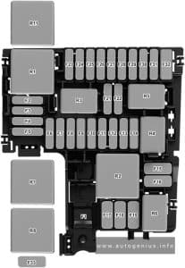
Dodge Hornet (2023 – 2024) – fuse box diagram

Dodge Hornet (2023 – 2024) – fuse box diagram

Year of production: 2023, 2024


The Dodge Hornet compact crossover has been available since 2022. In this article, you’ll find fuse box diagrams for the 2023 and 2024 Dodge Hornet models, along with details on the location of the fuse panels within the vehicle and the function of each fuse and relay (fuse layout).


Passenger compartment Fuse Box

Fuse Box Location

The interior fuse panel is located under the driver’s side lower instrument panel.

Dodge Hornet (2023 - 2024) - fuse box location - passenger compartment
Dodge Hornet (2023 – 2024) – fuse box location – passenger compartment

Fuse Box Diagram

Dodge Hornet (2023 - 2024) - fuse box diagram - passenger compartment
Dodge Hornet (2023 – 2024) – fuse box diagram – passenger compartment

Assignment of the fuses in the instrument panel

Amps Description
F31 7.5A Brown HVAC Relay Coil & Power Outlet / Seat Relay Coil
F33 20A Yellow Front Passenger Window Lifter
F34 20A Yellow Front Driver Window Lifter
F36 15A Blue HVAC / VTA / External Mirror / Ceiling Light / CVPM / Radio Mod / USB / AUX / DCSD / Electric Steering Lock
F37 10A Red Brake Switch / DASM / IPC
F38 20A Yellow Door Lock & Unlock / Liftgate Release
F42 7.5A Brown Brake System Module, Electric Power Steering
F43 20A Yellow Bi-Directional Washer Pump
F47 20A Yellow Rear Left Window Lifter
F48 20A Yellow Rear Right Window Lifter
F49 7.5A Brown Park Assist, Blind Spot, Voltage Stabilizer, Humidity Sensor, Electronic Steering Lock, Temp Sense, Mirror, Heated Seats, Light And Rain Sensor, Start Stop Switch
F50 7.5A Brown Occupant Restraint Controller
F51 7.5A Brown Electronic Climate Control, Occupant Classification, RearView Camera, Climate Control, Headlamp Leveling, Terrain Select, Heated Rear Window, Trailer Tow, Haptic Lane Mod
F53 7.5A Brown HCP / Reverse Gear / ISNSR / A/C Compressor / HVAC / Defrosting / Right & Left Headlamp Leveling / LDW / Alarm Mod / Psg Airbag / Trailer Tow Mod / AFLM / Air Quality Sensor / ASBM
F94 15A Blue Power Outlet

Engine Compartment Fuse Box

Fuse Box Location

Dodge Hornet (2023 - 2024) - fuse box location - engine compartment
Dodge Hornet (2023 – 2024) – fuse box location – engine compartment


Fuse Box Diagrams

Gasoline Engine
Dodge Hornet (2023 - 2024) - fuse box diagram - engine compartment (gasoline)
Dodge Hornet (2023 – 2024) – fuse box diagram – engine compartment (gasoline engine)

Assignment of the fuses in the engine compartment (Gas)

Amps Description
F01 70A Tan BCM1
F02 70A Tan BCM2 / RDU
F03 20A Blue BCM3
F04 40A Green BCM Valves
F05 40A Orange PTC 1
F06 20A Yellow Front Wiper Motor
F07 20A Yellow DTCM
F08 30A Pink Power Supply F24 – F87 – Fxx
F09 7.5A Brown ECM T09
F10 15A Blue Horn
F11 5A Tan Engine Secondary Loads
F14 7.5A Brown LTR
F15 40A Orange BSM Pump
F16 10A Red ECM / TCM / AGSM
F17 10A Red Engine Primary Loads
F18 5A Tan IGNM
F19 7.5A Brown A/C Compressor
F20 15A Blue Rear Cargo Outlet
F21 20A Yellow Fuel Pump
F22 15A Blue ECM
F23 5A Tan USB / Aux Outlet
F24 10A Red DTCM
F30 5A Tan AWD DTCM
F81 30A Green Brake Booster Vacuum Pump
F82 40A Green 2024: External Oil Pump (if equipped)
F83 40A Green HVAC Fan
F84 7.5A Brown Rad Fan Enable
F87 5A Tan AGSM
F88 7.5A Brown Heated Mirrors & Washer Nozzle
F89 30A Pink Rear Window Defrost
F90 5A Tan Intelligent Battery Sensor
T02 Not Used
T03 30A Horn Relay
T05 30A A/C Compressor Relay
T06 30A Rad Fan Enable Relay
T07 50A Aux.1 / DTCM Relay
T08 30A HVAC Fan Relay
T09 30A Engine Main Relay
T10 Not Used
T14 30A Rear Cargo Power Outlet Relay
T17 30A Rear Window Defrost / Heated Mirrors Relay
T19 Not Used
T20 30A Starter Relay R1
T31 30A Fuel Pump Relay
T89 Not Used
T90 30A Brake Booster Vacuum Pump Relay


Hybrid
Dodge Hornet (2023 - 2024) - fuse box diagram - engine compartment (hybrid)
Dodge Hornet (2023 – 2024) – fuse box diagram – engine compartment (hybrid)

Assignment of the fuses in the engine compartment (Hybrid)

Amps Description
F01 70A Tan BCM1
F02 70A Tan BCM2 / RDU
F03 20A Blue BMC3
F04 40A Green BCM Valves
F05 40A Orange PTC 1
F06 20A Yellow Front Wiper Motor
F07 50A Red AUX 1 RDU
F08 30A Pink Power Supply F24 – F87 – Fxx
F09 7.5A Brown ECM T09
F10 15A Blue Horn
F11 5A Tan Engine Secondary Loads
F14 7.5A Brown LTR
F15 70A Tan BSM Pump
F16 10A Red ECM / TCM / AGSM
F17 10A Red Engine Primary Loads
F18 5A Tan IGNM (if equipped)
F19 7.5A Brown A/C Compressor
F20 15A Blue Rear Cargo Outlet
F21 20A Yellow Fuel Pump
F22 20A Yellow Engine Primary Loads
F23 5A Tan USB / Aux Outlet
F24 10A Red TCM
F30 Spare
F81 40A Orange AUX 2 RDU
F82 40A Green External Oil Pump (AT) (if equipped)
F83 40A Green HVAC Fan
F84 7.5A Brown Rad Fan Enable
F87 5A Tan AGSM
F88 7.5A Brown Heated Mirrors & Washer Nozzle
F89 30A Pink Rear Window Defrost
F90 5A Tan Intelligent Battery Sensor
Fxx 25A Clear PIM
T02 Not Used
T03 30A Horn Relay
T05 30A A/C Compressor Relay
T06 30A Rad Fan Enable Relay
T07 50A Aux.1 Relay
T08 30A HVAC Fan Relay
T09 30A Engine Main Relay
T10 Not Used
T14 30A Rear Cargo Power Outlet Relay
T17 30A Rear Window Defrost / Heated Mirrors Relay
T19 30A External Oil Pump Relay
T20 30A Starter Relay R1
T31 30A Fuel Pump Relay
T89 Not Used
T90 30A Brake Booster Vacuum Pump Relay


Supplemental Fuse Box (Hybrid)
Dodge Hornet (2023 - 2024) - fuse box diagram - engine compartment (supplemental fuse box hybrid)
Dodge Hornet (2023 – 2024) – fuse box diagram – engine compartment (supplemental fuse box hybrid)
Amps Description
F01 5A Tan Electric Air Heater (EAH)
F02 7.5A Brown Electric Air Compressor (EAC)
F03 5A Tan Integrated Dual Charge Module (IDCM)
F04 5A Tan Charge Port Indicator Module (CPIM)
F05 15A Blue Power Electronic Coolant Pump 2 (PECP2)
F06 15A Blue Power Electronic Coolant Pump (PECP)
F07 5A Tan Aux Heater Pump (AHP)
F08 5A Tan PIM Feed 1
F09 10A Red BPCM Feed 1
F10 5A Tan PIM Feed 3
F11 10A Red BPCM Feed 2
F12 5A Tan Electronic Pedestrian Protection Module (EPPM)

Cargo Compartment Fuse Box

Fuse Box Location

To access the fuses, remove the access panel from the left rear section of the cargo area. The fuses may be housed in two separate units. Fuse Holder №1 is positioned nearest to the rear of the vehicle, while Fuse Holder №2 (if equipped with trailer towing) is located closer to the front of the vehicle.

Dodge Hornet (2023 - 2024) - fuse box location - cargo compartment
Dodge Hornet (2023 – 2024) – fuse box location – cargo compartment


Fuse Box Diagram

Dodge Hornet (2023 - 2024) - fuse box diagram - cargo compartment
Dodge Hornet (2023 – 2024) – fuse box diagram – cargo compartment

Assignment of the fuses in cargo compartment

Amps Description
Fuse Holder №1
F1 20A Yellow Sunroof
F2
F3 30A Green Power Liftgate Module (PLGM)
F4 5A Tan Driver And Passenger Ventilated Seats (HMSM)
F5 25A Clear Heating And Memory Drive Seat Module 1
F6 10A Red Heating And Memory Drive Seat Module 2
F7 7.5A Brown Driver And Passenger Lumbar Regulator (Without HMSM)
F8 20A Yellow Passenger Seat SW (HMSM)
Fuse Holder №2
F3 5A Tan Hands-Free Power Liftgate (HFRM)
F4 7.5A Brown Damping Control Module
F5 5A Tan Changeover Valve Feed (ELCM)
F8 7.5A Brown Damping Control Module
Maxi Fuse Holder
F01 30A Green Amplifier
On the Rear Cargo Fuse/Relay Distribution Unit bracket, there is a Maxi Fuse holder for the Amplifier (if equipped).

WARNING: Terminal and harness assignments for individual connectors will vary depending on vehicle equipment level, model, and market.