Chevrolet Equinox (2009) – fuse and relay box diagram
Year of production: 2009
This article focuses on the first-generation Chevrolet Equinox, manufactured between 2005 and 2009. It includes fuse box diagrams for the 2009 models, details the locations of the fuse panels within the vehicle, and provides information on the function and layout of each fuse and relay.
Passenger compartment
Fuse Box Location
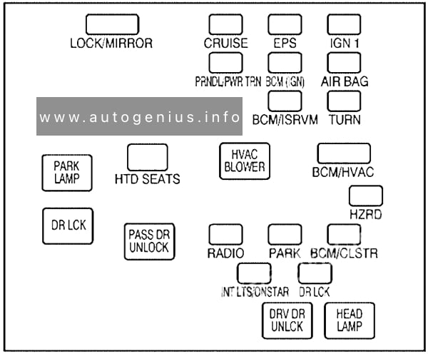
The fuse box is located under the dashboard on the passenger’s side of the center console, behind the cover.
Fuse Box Diagram

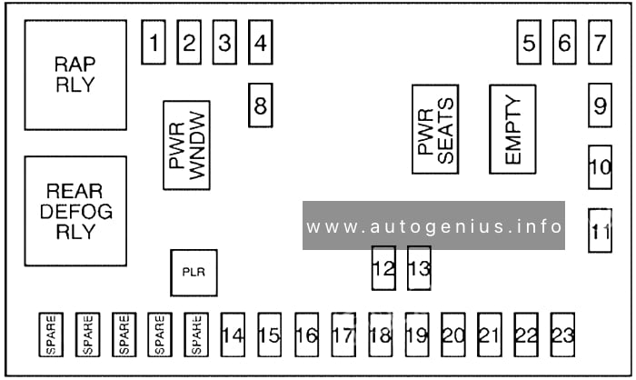
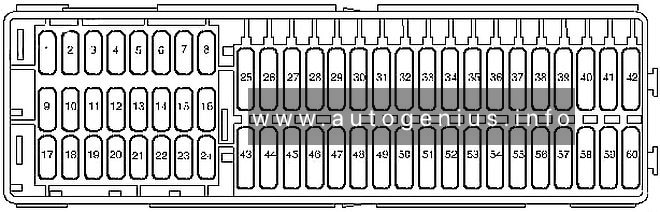
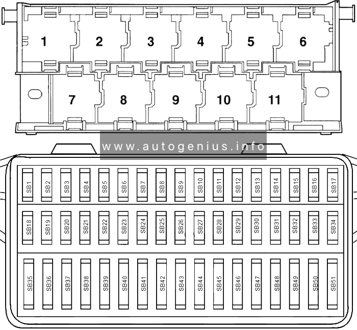
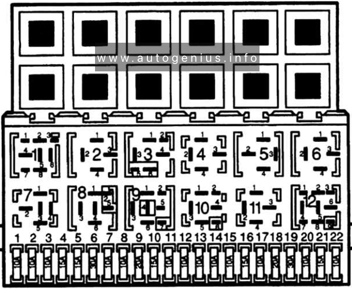
Assignment of the fuses and relays in the passenger compartment
| № | Description |
|---|---|
| 1 | Sunroof, Inside Rear View Mirror, Compass |
| 2 | Rear Seat Entertainment |
| 3 | Rear Wiper |
| 4 | Liftgate |
| 5 | Airbags |
| 6 | Heated Seats |
| 7 | Driver’s Side Turn Signal |
| 8 | Door Locks |
| 9 | Automatic Occupant Sensing Module |
| 10 | Power Mirrors |
| 11 | Passenger’s Side Turn Signal |
| 12 | Amplifier |
| 13 | Steering Wheel Illumination |
| 14 | Infotainment |
| 15 | Climate Control System, Remote Function Actuator |
| 16 | Canister Vent |
| 17 | Radio |
| 18 | Cluster |
| 19 | Ignition Switch |
| 20 | Body Control Module |
| 21 | Communications Integration Module |
| 22 | Center High-Mounted Stoplamp, Dimmer |
| 23 | Interior Lights |
| SPARE | Spare fuses |
| PWR WNDW | Power Windows (Circuit Breaker) |
| PWR SEATS | Power Seats (Circuit Breaker) |
| EMPTY | Empty (Circuit Breaker) |
| PLR | Fuse Puller |
| Relays | |
| RAP RLY | Retained Accessory Power Relay |
| REAR DEFOG RLY | Rear Defogger Relay |
Engine Compartment
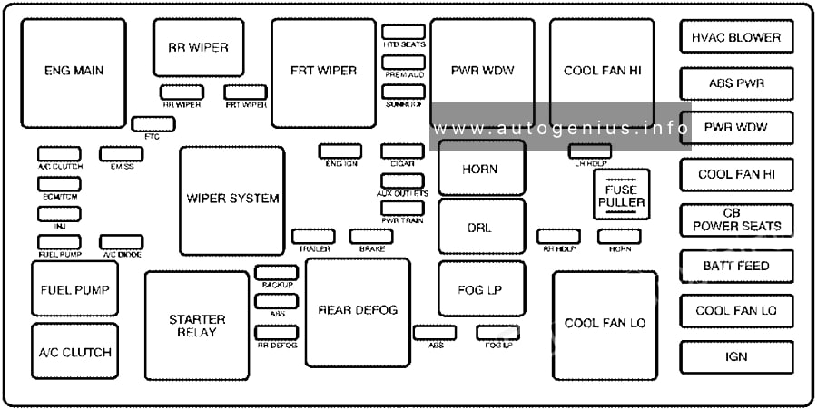
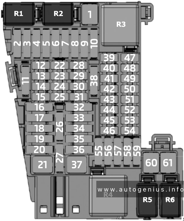
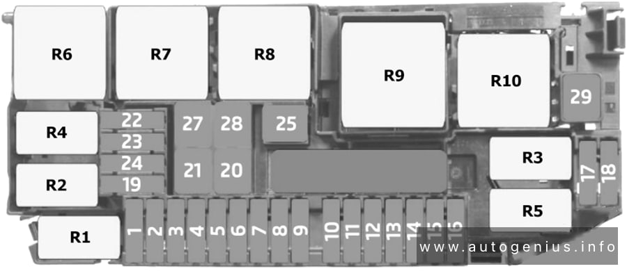
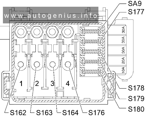
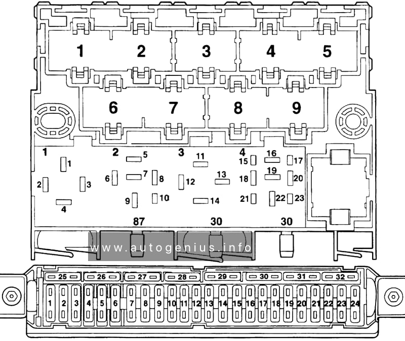
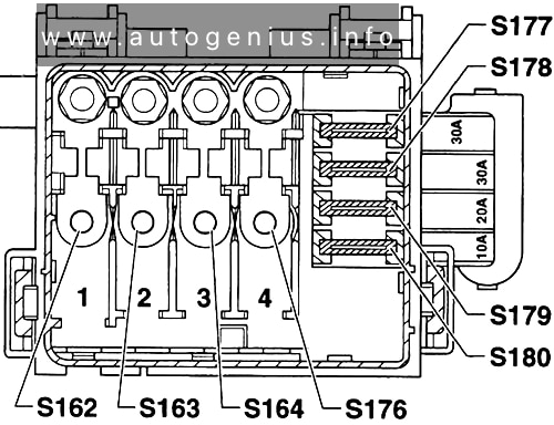
Fuse Box Diagram
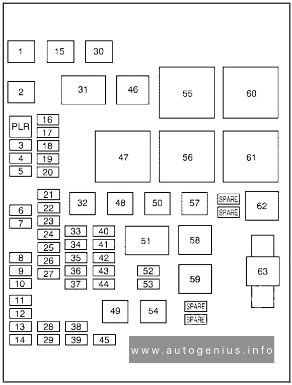
Assignment of the fuses and relays in the engine compartment
| № | Description |
|---|---|
| 1 | Cooling Fan 2 |
| 2 | Cooling Fan 1 |
| 3 | Auxiliary Power |
| 4 | Rear HVAC |
| 5 | Spare |
| 6 | Sun Roof |
| 7 | Anti-lock Brake System |
| 8 | Air Conditioning Clutch |
| 9 | Driver’s Side Low-Beam |
| 10 | Daytime Running Lamp 2 |
| 11 | Passenger’s Side High-Beam |
| 12 | Passenger’s Side Park Lamp |
| 13 | Horn |
| 14 | Driver’s Side Park Lamp |
| 15 | Starter |
| 16 | Electronic Throttle Control, Engine Control Module |
| 17 | Emission Device 1 |
| 18 | Even Coils, Injectors |
| 19 | Odd Coils, Injectors |
| 20 | Emission Device 2 |
| 21 | Spare |
| 22 | Powertrain Control Module, Ignition |
| 23 | Transmission |
| 24 | Mass Airflow Sensor |
| 25 | Airbag Display |
| 26 | Spare |
| 27 | Stoplamp |
| 28 | Passenger’s Side Low-Beam |
| 29 | Driver’s Side High-Beam |
| 30 | Battery Main 3 |
| 32 | Spare |
| 33 | Engine Control Module, Battery |
| 34 | Transmission Control Module, Battery |
| 35 | Trailer Park Lamp |
| 36 | Front Wiper |
| 37 | Driver’s Side Trailer Stoplamp, Turn Signal |
| 38 | Spare |
| 39 | Fuel Pump |
| 40 | Not Used |
| 41 | All-Wheel Drive |
| 42 | Regulated Voltage Control |
| 43 | Passenger’s Side Trailer Stoplamp, Turn Signal |
| 44 | Spare |
| 45 | Front, Rear Washer |
| 48 | Rear Defogger |
| 49 | Anti-lock Brake System Motor |
| 50 | Battery Main 2 |
| 52 | Daytime Running Lamps |
| 53 | Fog Lamps |
| 54 | Climate Control System Blower |
| 57 | Battery Main 1 |
| 63 | Megafuse / Electric Power Steering |
| Relays | |
| 31 | Ignition Main |
| 46 | Air Conditioning Compressor Clutch |
| 47 | Powertrain |
| 51 | Spare |
| 55 | Crank |
| 56 | Fan 1 |
| 58 | Passenger’s Side Trailer Stoplamp, Turn Signal |
| 59 | Driver’s Side Trailer Stoplamp, Turn Signal |
| 60 | Fan 3 |
| 61 | Fan 2 |
| 62 | Fuel Pump |
WARNING: Terminal and harness assignments for individual connectors will vary depending on vehicle equipment level, model, and market.