Audi 100 (C4; 1992 – 1994) – fuse box diagram
Year of production: 1992, 1993, 1994
This article covers the second-generation Audi 100 (C4), produced from 1990 to 1994. It includes fuse box diagrams for the 1992, 1993 and 1994 models, provides details on the location of the fuse panels inside the vehicle, and explains the function and layout of each fuse.
Passenger compartment
Fuse box diagram
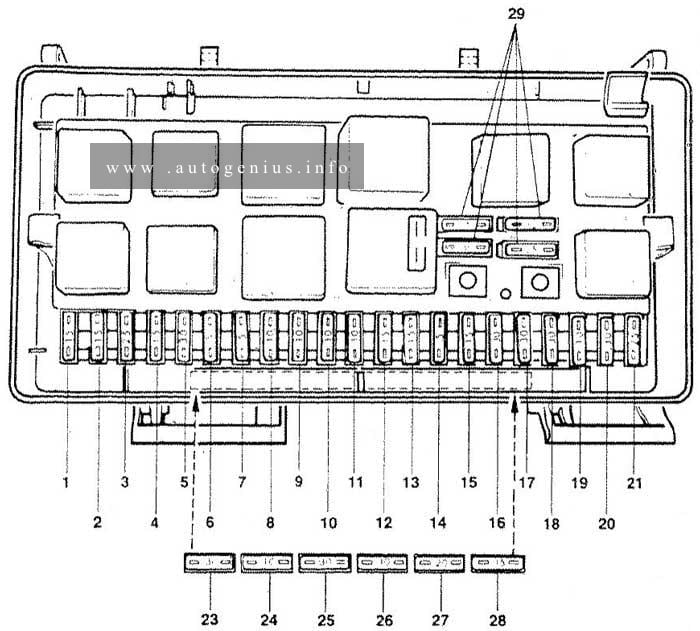
Assignment of the fuses in the passenger compartment (instrument panel)
| № |
A |
Description |
| 1 | 15 | Rear fog lights |
| 2 | 15 | Emergency flash switch, anti-theft system (USA only) |
| 3 | 25 | Horns, brake lights switch |
| 4 | 15 | Luggage compartment, light, cigar lighter, interior lights |
| 5 | 30 | Not used |
| 6 | 5 | Tail lights, side marker light, RF |
| 7 | 5 | Tail lights, side marker light, LF |
| 8 | 10 | Headlight, hi-beam, right |
| 9 | 10 | Headlight, hi beam, left |
| 10 | 10 | Headlight, lo beam, right |
| 11 | 10 | Headlight, lo beam, left |
| 12 | 15 | Automatic transmission, backup lights, interior lights |
| 13 | 15 | Fuel pump |
| 14 | 5 | License plate lights, glove compartment light, engine compartment light, center console |
| 15 | 25 | Wipers/washer |
| 16 | 30 | Rear defogger |
| 17 | 30 | Fresh air fan, air conditioning |
| 18 | 5 | Power mirror switch |
| 19 | 10 | Central locking system, anti-theft system (USA only) |
| 20 | 30 | Heated seats |
| 21 | 25 | Fuel injection control unit, diagnostic |
| 22 | — | Open |
| 23 | — | Open |
| 24 | — | Open |
| 25 | — | Open |
| 26 | 5 | Speedometer, power mirrors |
| 27 | 10 | Ignition control unit |
| 28 | 15 | Fuel injection control unit, electronic engine cintrol |
| 29 | — | Open |
| 30 | 5 | Automatic transmission |
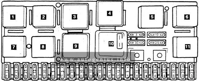
| № | Description |
| 1 | Rear fog light jumper plug |
| 2 | Rad. cooling fan relay 2nd stage |
| 3 | Rad. cooling fan relay after run control unit |
| 4 | Open |
| 5 | Load reduction relay |
| 6 | Open |
| 7 | Horn relay |
| 8 | Automatic transmission/anti-theft relay |
| 9 | Wash/wiper intermit, relay |
| 10 | Fuel pump relay, J17 |
| 11 | Open |
Fuse box diagram
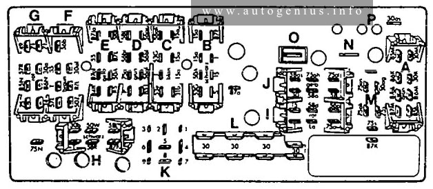
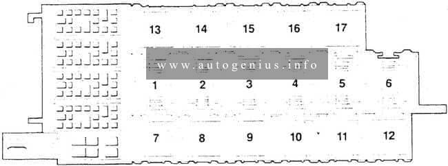
Assignment of the fuses in the passenger compartment (instrument panel)
| № |
Description | Color |
| A | Air conditioning connector | Gray |
| B | Right front wiring harness connector | Black |
| C | Instrument panel connector | Blue |
| D | Left front wiring harness connector | Green |
| E | Left front wiring harness connector | Yellow |
| F | Instrument panel connector | Brown |
| G | Instrument panel connector | Red |
| H | Rear wiring harness connector | Black |
| I | Instrument panel connector | Red |
| J | Instrument panel connector | Yellow |
| K | — | — |
| L | Single connector (terminal 30) connector | Colorless |
| M | For optional equipment connector | Colorless |
| N | — | — |
| O | — | — |
| P | To fuse 26 | — |
WARNING: Terminal and harness assignments for individual connectors will vary depending on vehicle equipment level, model, and market.