Eagle Talon (1991) – fuse and relay box diagram
Year of production: 1991
This article covers the first-generation Eagle Talon produced from 1989 to 1998. It includes fuse box diagrams for the 1991 models, provides details on the location of the fuse panels inside the vehicle, and explains the function and layout of each fuse.
Fuse box diagram
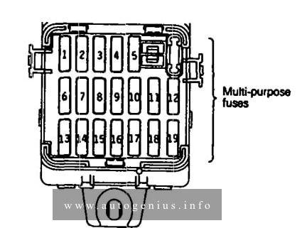
Assignment of the fuses in the fuse box
| Power supply circuit | No. | A | Load circuit | |
| Battery | 1 | 10 | Automatic seatbelt control unit, key reminder switch, passing control relay, seatbelt warning buzzer, utillight relay | |
| Ignition switch | IG2 | 2 | — | — |
| 3 | 10 | Air conditioner contlol unit, air conditioner switch, defogger timer, heater relay, power window relay, transistor relay*, daytime running light relay 2*, ABS relay | ||
| ACC | 4 | 10 | Radio | |
| 5 | 15 | Cigarette lighter, remote controlled mirror | ||
| Battery | 6 | 15 | Door lock relay, door lock control unit | |
| Ignition switch | IG2 | 7 | 10 | 4-speed automatic transaxle control unit, auto-cruise control unit <A/T>, combination meter |
| 8 | — | — | ||
| ACC | 9 | 15 | Intermittent wiper relay, wiper motor, washer motor | |
| 10 | 10 | Headlight relay, horn, theft-alarm control unit, daytime running high relay 1* | ||
| IG1 | 11 | 10 | Auto-cruise control unit, auto-cruise control actuator automatic seatbelt contyrol unit, combination meter, theft-alarm control unit, seatbelt timer* | |
| 12 | 10 | Tum-signal and hazard flasher unit | ||
| Battery | 13 | — | — | |
| 14 | 10 | Theft-alarm horn relay | ||
| 15 | — | — | ||
| 16 | 30 | Blower motor | ||
| 17 | 15 | Stop light | ||
| Ignition switch | IG1 | 18 | 10 | Back-UP light < M/T>, dome light relay |
| Battery | 19 | 10 | 4-speed automatic transaxle control unit, dome light, door-ajar warning light, foot light, ignition key illumination light, luggage compartment light, MPI control unit, radio, security light, ABS relay | |
| *: – vehicle for Canada | ||||
WARNING: Terminal and harness assignments for individual connectors will vary depending on vehicle equipment level, model, and market.