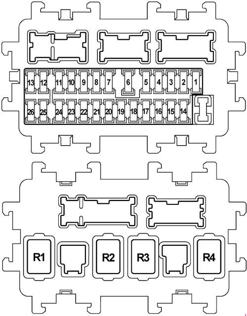
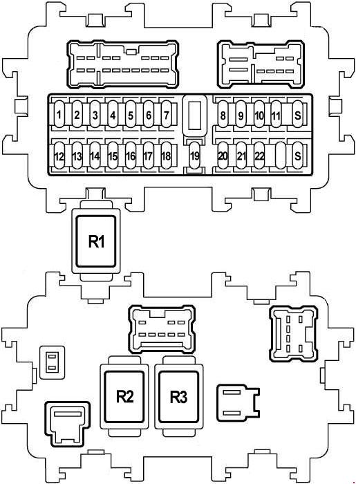
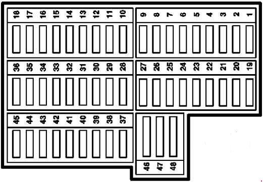
No.
|
A
|
Circuit Protected |
| 1 |
10 |
Main Power Supply and Ground Circuit, Injector, Remote Keyless Entry System, Intelligent Key System, Nissan Anti-Theft System, Power Window, Rear Window Defogger, Sunroof, Automatic Drive Positioner, Power Seat, Headlamp, Auto Light Control, Headlamp Aiming Control System, Front Fog Lamp, Rear Fog Lamp, Turn Signal and Hazard Warning Lamp, Combination Switch, Parking Lamps, License and Tail Lamps, Interior Room Lamp, Illumination, Warning Chime, Front Wiper and Washer, Headlamp Washer, Vehicle Information and Integrated Switch System |
| 2 |
10 |
Starting Signal |
| 3 |
10 |
Heated Seat |
| 4 |
10 |
Audio |
| 5 |
15 |
Power Outlet |
| 6 |
10 |
Remote Keyless Entry System, Power Door Mirror, Rear Window Defogger, Automatic Drive Positioner, Air Conditioner, Headlamp, Auto Light Control, Headlamp Aiming Control System, Front Fog Lamp, Rear Fog Lamp, Turn Signal and Hazard Warning Lamp, Combination Switch, Illumination, Parking Lamps, License and Tail Lamps, Speedometer, Tachometer, Temp. and Fuel Gauges, Headlamp Washer, Audio, Audio Antenna, Vehicle Information and Integrated Switch System, Audio Visual Communication Line |
| 7 |
15 |
Cigarette Lighter |
| 8 |
10 |
Heated Seat, Air Conditioner |
| 9 |
10 |
Automatic Drive Positioner |
| 10 |
15 |
Air Conditioner |
| 11 |
15 |
Air Conditioner |
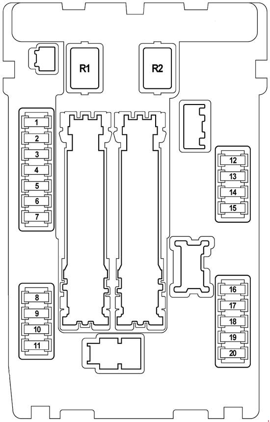
| 12 |
10 |
Automatic Speed Control Device (ASCD) Brake Switch, MIL & Data Link Connector, Vehicle Speed Sensor, Non-Detective Items, Shift Lock System, Vehicle Dynamics Control System, Intelligent Key System, Nissan Anti-Theft System, Rear Window Defogger, Heated Seat, Rear Sunshade, Air Conditioner, Parking Lamps, License and Tail Lamps, Headlamp Aiming Control System, Illumination, Adaptive Front Lighting System, Speedometer, Tachometer, Temp. and Fuel Gauges, Warning Chime, Warning Lamps, A/T Indicator Lamp, CVT Indicator Lamp, Audio, Audio Visual Communication Line, Vehicle Information and Integrated Switch System |
| 13 |
10 |
Supplemental Restraint System |
| 14 |
10 |
Park/Neutral Position Switch, Automatic Speed Control Device (ASCD) Indicator, MIL & Data Link Connector, Non-Detective Items, Anti-Lock Brake System, Vehicle Dynamics Control System, Supplemental Restraint System, Rear Sunshade, Intelligent Key System, Charging System, Headlamp, Front Fog Lamp, Rear Fog Lamp, Turn Signal and Hazard Warning Lamp, Back-Up Lamp, Illumination, Parking Lamps, License and Tail Lamps, Speedometer, Tachometer, Temp. and Fuel Gauges, Warning Chime, Warning Lamps, A/T Indicator Lamp, CVT Indicator Lamp, Audio, Vehicle Information and Integrated Switch System |
| 15 |
15 |
Air Massage Seat |
| 16 |
– |
Not Used |
| 17 |
15 |
Power Door Lock, Automatic Speed Control Device (ASCD) Indicator, A/T Fluid Temperature Sensor and TCM Power Supply, Main Power Supply and Ground Circuit, Non-Detective Items, Manual Mode Switch, Shift Lock System, Vehicle Dynamics Control System, Remote Keyless Entry System, Intelligent Key System, Nissan Anti-Theft System, Trunk Lid Opener, Power Window, Sunroof, Rear Window Defogger, Automatic Drive Positioner, Auto Light Control, Headlamp Aiming Control System, Headlamp, Power Seat, Front Fog Lamp, Rear Fog Lamp, Turn Signal and Hazard Warning Lamp, Combination Switch, Parking Lamps, License and Tail Lamps, Interior Room Lamp, Illumination, Warning Chime, Warning Lamps, A/T Indicator Lamp, CVT Indicator Lamp, Vehicle Information and Integrated Switch System, Front Wiper and Washer |
| 18 |
15 |
Shift Lock System, Power Door Lock, Intelligent Key System, Nissan Anti-Theft System, Automatic Drive Positioner, Warning Chime, Interior Room Lamp |
| 19 |
10 |
Electronic Controlled Engine Mount, MIL & Data Link Connector, Non-Detective Items, Manual Mode Switch, Intelligent Key System, Vehicle Dynamics Control System, Nissan Anti-Theft System, Air Conditioner, Illumination, Parking Lamps, License and Tail Lamps, Speedometer, Tachometer, Temp. and Fuel Gauges, Warning Chime, Warning Lamps, A/T Indicator Lamp, CVT Indicator Lamp, Audio, Vehicle Information and Integrated Switch System, Audio Visual Communication Line |
| 20 |
10 |
Automatic Speed Control Device (ASCD) Brake Switch, Brake Switch, Non-Detective Items, Shift Lock System, Stop Lamp, Anti-Lock Brake System, Vehicle Dynamics Control System |
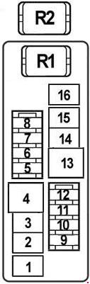
| 21 |
10 |
Interior Room Lamp, Vanity Mirror Lamp |
| 22 |
10 |
Fuel Lid Opener |
| S |
– |
Spare Fuse |
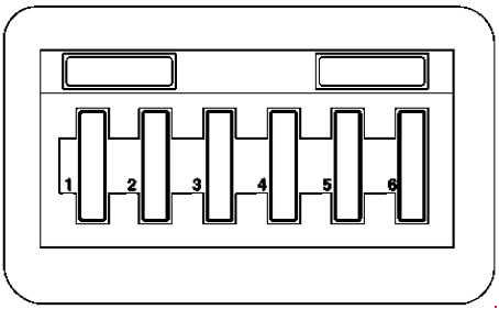
Relay
|
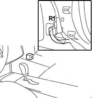
| R1 |
Heated Seat Relay |
| R2 |
Blower Relay |
| R3 |
Accessory Relay |