* These items are only for the cab specification machine.
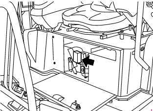
Fusible Link
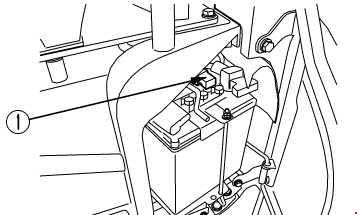
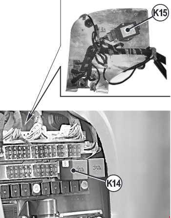
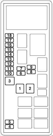
If the power does not come on when the starting switch is turned to the ON position, the wire-shaped fusible link ® may be cut, so remove the cover on the right side of the chassis, and check or replace.
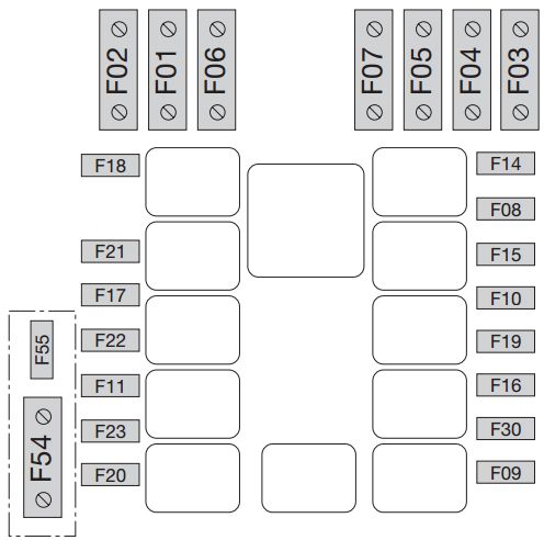
Komatsu PC40-7 – fuse box diagram – fusible link
WARNING: Terminal and harness assignments for individual connectors will vary depending on vehicle equipment level, model, and market.
* These items are only for the cab specification machine.
Fusible Link
If the power does not come on when the starting switch is turned to the ON position, the wire-shaped fusible link ® may be cut, so remove the cover on the right side of the chassis, and check or replace.
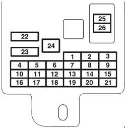
Komatsu PC30-7 – fuse box diagram – fusible link
WARNING: Terminal and harness assignments for individual connectors will vary depending on vehicle equipment level, model, and market.
* These items are only for the cab specification machine.
Fusible Link
If the power does not come on when the starting switch is turned to the ON position, the wire-shaped fusible link ® may be cut, so remove the cover on the right side of the chassis, and check or replace.
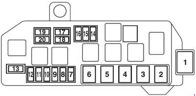
Komatsu PC25-1 – fuse box diagram – fusible link
WARNING: Terminal and harness assignments for individual connectors will vary depending on vehicle equipment level, model, and market.
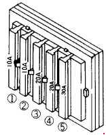
High-low speed switch, PPC solenoid valve, display power supply
5
15
Horn
6
15
Windshield wiper, overhead light, heating (for machine with cab)
7
10
Optional equipment
8
10
Revolving light
9
—
Free
10
—
Free
11
—
Free
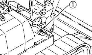
Main Fuse
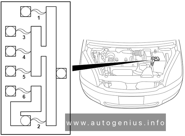
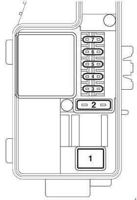
If the starter does not run when the ignition switch is turned to position ON, the fuse (1) may have blown. Open the cover on the left side of the machine to check the fuse and change it if necessary. The main fuse is positioned on the battery.
Komatsu PC14R-2 – fuse box diagram – main fuse
WARNING: Terminal and harness assignments for individual connectors will vary depending on vehicle equipment level, model, and market.
Year of production: 2003, 2004, 2005, 2006, 2007, 2008
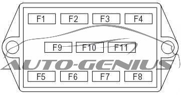
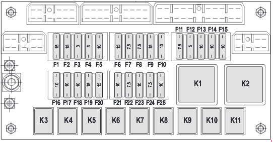
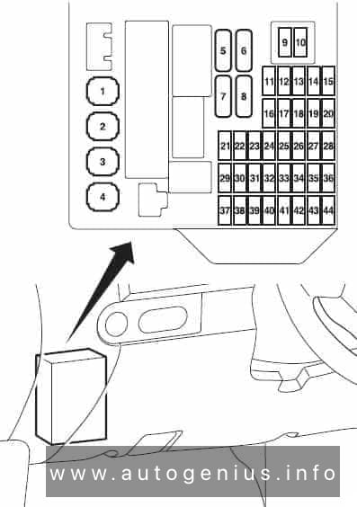
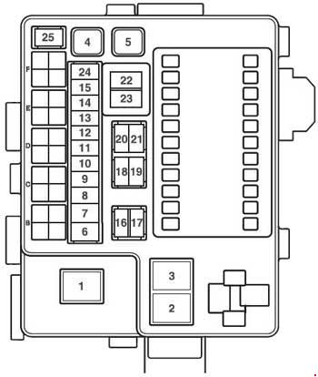
This article focuses on the pre-facelift Mitsubishi Colt (Z30), manufactured from 2002 to 2008. It includes fuse box diagrams for the 2003 through 2009 models, provides details on the locations of the fuse panels inside the vehicle, and explains the purpose of each fuse (fuse layout).
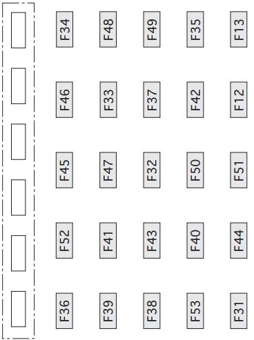
Passenger Compartment Fuse Box
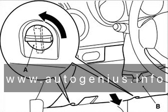
Fuse Box Location
It is located behind the cover in front of the driver’s seat. Turn the clips (A) anticlockwise, then remove the cover (B).
ETACS-ECU, windshield wiper motor and washer motor
14
7.5A
Fog lamp switch, hazard warning switch, position lamp and tail lamp
15
7.5A
Licence plate lamp, position lamp and tail lamp
16
20A
Air flow sensor (4G15), camshaft position sensor, crank angle sensor, EGR valve (CVT), engine control relay, engine-CVT-ECU (CVT), engine-ECU (M/T), fuel pressure control solenoid valve (4G15), injector, oxygen sensor, primary speed sensor (CVT), purge control solenoid valve, oil feeder control valve, secondary speed sensor (CVT), turbine speed sensor (CVT), throttle valve control servo relay and wastegate solenoid valve (4G15)
17
15A
Fuel pump and gauge unit
18
10A
Horn and horn relay
19
10A
Headlamp (HI)
20
10A
Headlamp (HI)
21
–
–
22
–
–
23
7.5A
Door mirror assembly
24
10A
A/C compressor, A/C compressor relay, engine-CVT-ECU (CVT) and engine-ECU (M/T)
25
15A
Cigarette lighter
26
15A
ETACS-ECU, rear wiper motor and washer motor
27
20A
Sunroof motor assembly
28
–
–
29
10A
–
30
15A
–
31
10A
ETACS-ECU and turn-signal lamp
32
10A
–
33
15A
Diagnosis connector, ETACS-ECU, door lock actuator and door mirror assembly
34
15A
Fog lamp and fog lamp relay
35
15A
Headlamp (LO)
36
15A
Headlamp (LO)
37
7.5A
Engine-CVT-ECU (CVT), SRS-ECU and back-up lamp
38
7.5A
Engine-CVT-ECU (CVT) engine-ECU (M/T) and fuel pump relay
39
10A
Ignition coil and noise condenser
40
7.5A
ABS-ECU (4A91), ASC-ECU (4G15)>, column switch, combination meter, EPS-ECU, ETACS-ECU, SRS-ECU, G and yaw rate sensor and steering wheel sensor
41
7.5A
Blower relay, combination meter, cooling fan control relay, engine-CVT-ECU (CVT), engine-ECU (M/T), outside/inside air selection damper control motor and rear window defogger relay