Ferrari Enzo (2002 – 2003) – fuse box diagram
Year of production: 2002, 2003, 2004
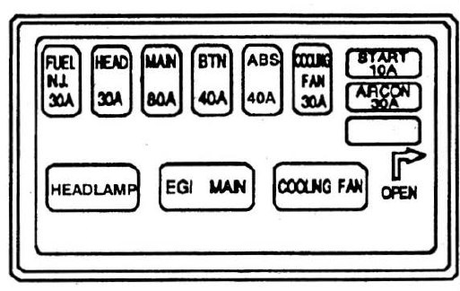
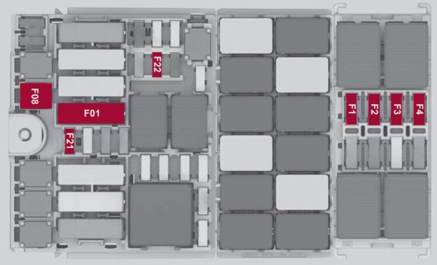
Fuse boxes in the front luggage compartment
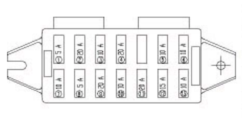
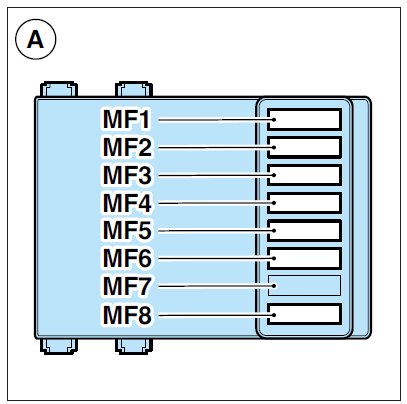
Fuse box A
| Fuse location | Ampere rating [A] | Function |
| MF1 | 40 | Right-hand fan |
| MF2 | 30 | F1 Pump |
| MF3 | 80 | Front fuse box |
| MF4 | 20 | Sensing alternator |
| MF5 | 40 | Air-conditioner unit |
| MF6 | 40 | Left-hand fan |
| MF7 | — | Position availble |
| MF8 | 80 | Front fuse box |
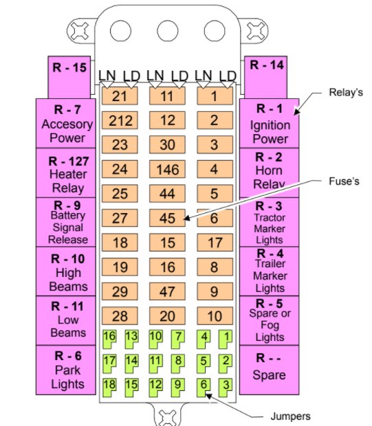
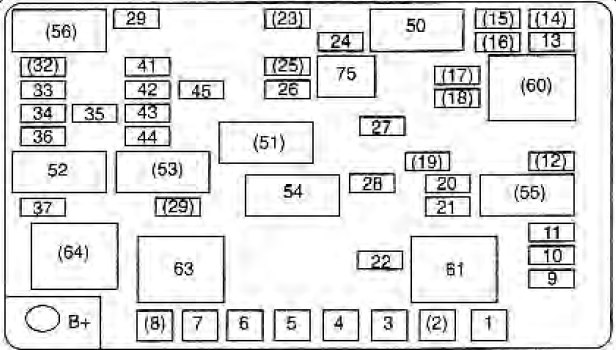
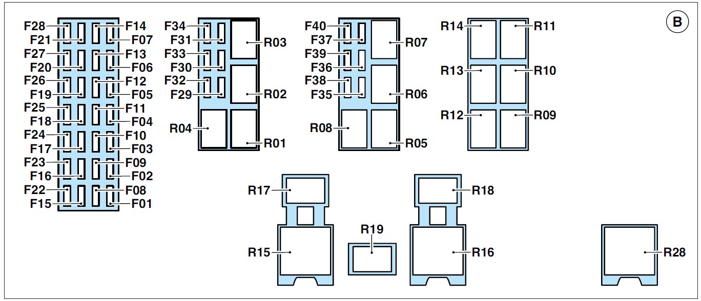
Fuse box B
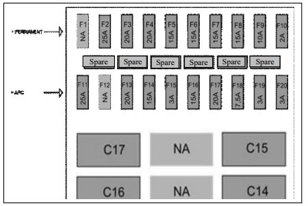
| Fuse location | Ampere rating [A] | Function |
| F01 | 10 | +15 LH Injection |
| F02 | 10 | +15 Inertia RH injection |
| F03 | 15 | +30 LH fuel pump |
| F04 | 30 | Main LH Injection |
| F05 | 15 | Immobilizer |
| F06 | 10 | OBDII, parking, ceiling light doduco, (+30) engine signal |
| F07 | 20 | +30 F1 gearbox ECU |
| F08 | 5 | Relay coils (+15 ignition cut-out) |
| F09 | 10 | A.C. SYSTRM (+15 ignition cut-out) |
| F10 | 15 | Cigarette lighter, mirrors, ceilling light (+15 ignition cut-out) |
| F11 | 25 | Windscreen wipers, wiper/washer pumps (+15 ignition cut-out) |
| F12 | 15 | Battery charger |
| F13 | 30 | Headlight washer |
| F14 | 15 | Repeater node |
| F15 | 10 | Instrument (+30) |
| F16 | 7,5 | Steering column stalk and steering wheel ECU (+30) |
| F17 | 20 | +30 wing check control unit |
| F18 | 10 | Stop, clutch (+15 no cut-out upon ignition) |
| F19 | 7,5 | Instrument steering column stalk and steering wheel, immobilizer (+15 no cut-out upon ignition) repeater node |
| F20 | 10 | Boge, doduco, alternator (+15 device not cut-out upon ignition) |
| F21 | 10 | Airbag (+15 devices not cut out upon ignition) |
| F22 | — | Position avaible |
| F23 | 10 | Tyre pressure monitoring system |
| F24 | 7,5 | +30 A.C (signals) |
| F25 | 7,5 | Reverse gear |
| F26 | 15 | +30 RH fuel pump |
| F27 | 30 | RH main injection |
| F28 | 15 | Key (+30) |
| F29 | 15 | LH low beam light |
| F30 | 15 | RH low beam light |
| F31 | 15 | Horns |
| F32 | 10 | RH High beam light |
| F33 | 10 | LH High beam light |
| F34 | 7,5 | A.C. Compressor |
| F35 | — | Position avaible |
| F36 | 30 | 50 starter motor |
| F37 | 30 | Lift |
| F38 | 7,5 | RH parking light |
| F39 | 7,5 | LH parking light |
| F40 | 7,5 | Dipped, number-plate, interior lighting |
| Relay | Function | |
| R01 | MICRO SWITCH | Low beam lights |
| R02 | MICRO SWITCH | Compressor |
| R03 | MICRO SWITCH | Horns |
| R04 | MICRO SWITCH | High beam lights |
| R05 | MICRO SWITCH | Dipped, number-plate, interior lighting |
| R06 | MICRO SWITCH | Dipped – parking lights |
| R07 | MICRO SWITCH | Rear fog lights |
| R08 | MICRO SWITCH 30A | Starter motor |
| R09 | MICRO SWITCH | Windscreen wipers, 2 speed (switch) |
| R10 | MICRO SWITCH 30 A | Devices not cut out upon ignition |
| R11 | MICRO SWITCH | Windscreen washer |
| R12 | MICRO SWITCH | Reverse gear |
| R13 | MICRO SWITCH 30A | Devices cut out upon ignition |
| R14 | MICRO SWITCH | Windscreen wipers, 1 speed )switch) |
| R15 | 2to RH fan | |
| R16 | 2to LH fan | |
| R17 | 1to RH fan | |
| R18 | 1to LH fan | |
| R19 | Headlight washer | |
| R28 | F1 gearbox | |
Fuse boxes in the front luggage compartment
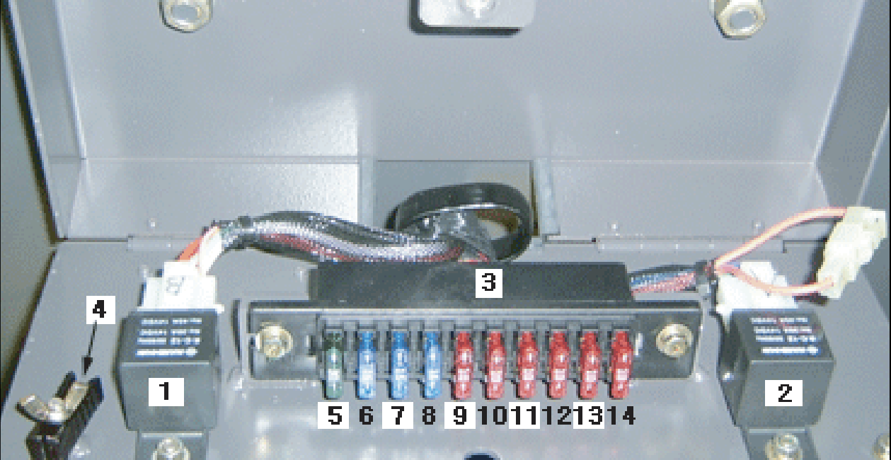
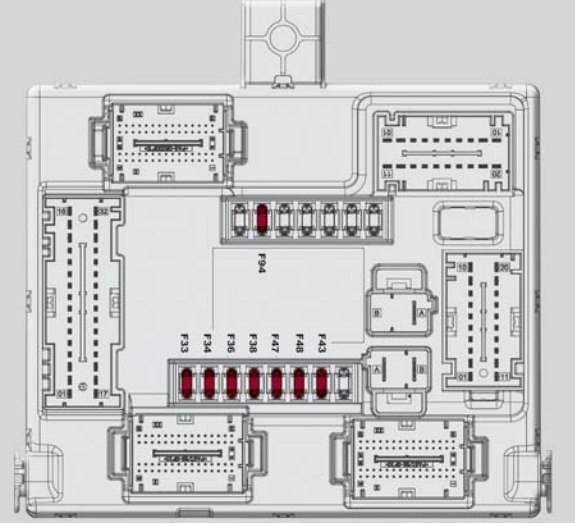
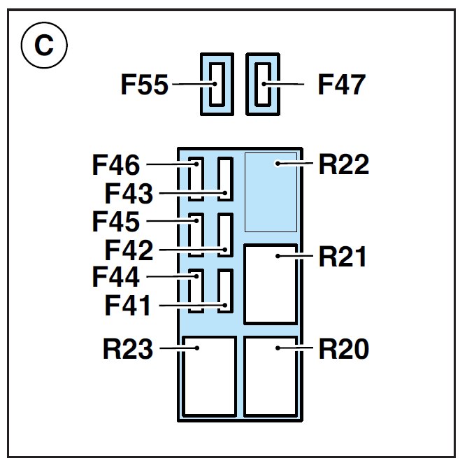
Fuse box C
| Fuse location | Ampere rating [A] | Function |
| F41 | 7,5 | +30 pin 62 injection |
| F43 | 15 | Injectors |
| F44 | 15 | Electric fans, air flow meter, etc. |
| F45 | 15 | Lambda sensor |
| F46 | 7,5 | Injection (+87 main relay) (pin 3) |
| F47 | 10 | Timing variator |
| F55 | 10 | ABS (+87 main relay) |
| Relay | Function | |
| R20 | MICROSWITCH BOSCH | Immobilizer (switch) |
| R21 | MICROSWITCH BOSCH | Fuel pump 1 speed |
| R22 | — | Position avaible |
| R23 | MICROSWITCH BOSCH | Main injection |
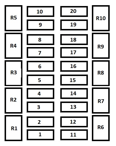
Fuse box D
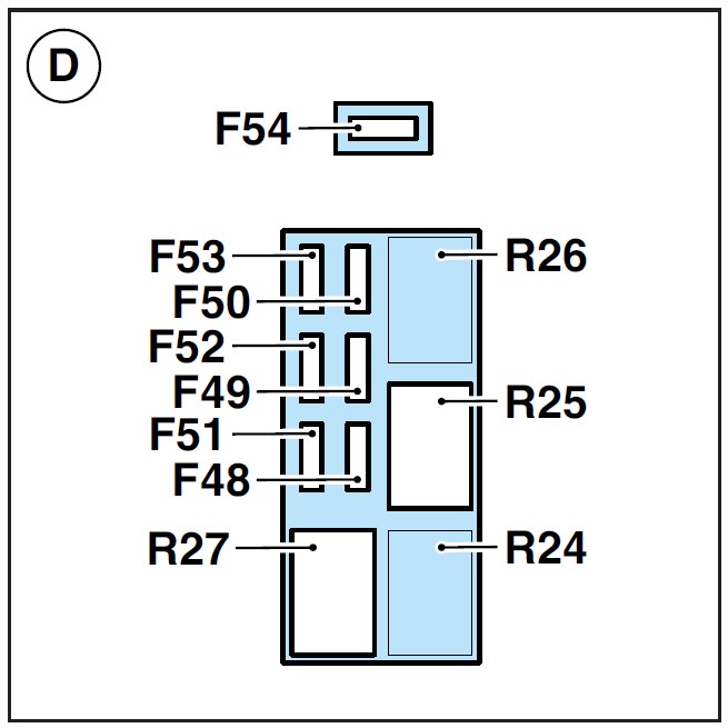
engine compartment (box D)
| Fuse location | Ampere rating [A] | Function |
| F48 | 7,5 | +30 pin 62 injection |
| F49 | 15 | Injectors |
| F50 | 15 | Coils |
| F51 | 15 | Electric fans, air flow, etc |
| F52 | 15 | Lambda sensor |
| F53 | 7,5 | Injection (+87 main relay) (pin 3) |
| F54 | 10 | Timing variator (deriv. 10) |
| Relay | Function | |
| R24 | — | Position avaible |
| R25 | MICROSWITCH BOSCH | Fuel pump 1 speed |
| R26 | — | Position available |
| R27 | MICROSWITCH BOSCH | Main injection |
WARNING: Terminal and harness assignments for individual connectors will vary depending on vehicle equipment level, model, and market.