Fiat Ducato (III FL; 2014 – 2019) – fuse and relay box diagram
Year of production: 2014, 2015, 2016, 2017, 2018, 2019
This article covers the third-generation (3rd generation), produced from 2014 to present. It includes fuse box diagrams for the 2014, 2015, 2016, 2017, 2018 and 2019 models, provides details on the location of the fuse panels inside the vehicle, and explains the function and layout of each fuse.
Passenger compartment
Fuse box diagram
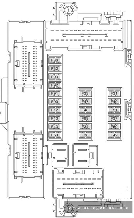
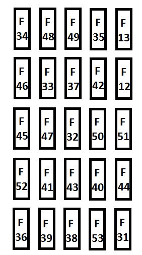
Assignment of the fuses in the passenger compartment (dashboard)
| № | Ampere rating [A] | Device protected |
|---|---|---|
| F12 | 7,5 | Right dipped beam headlight |
| F13 | 7,5 | Left dipped headlight |
| F31 | 5 | Engine compartment control unit relay, dashboard control unit relay (+key) |
| F32 | 7,5 | Lighting of roof lights in the passenger compartment (+battery) |
| F33 | 7,5 | Battery monitoring sensor for Start&Stop versions (+battery) |
| F34 | 7,5 | Minibus interior lights (emergency) |
| F35 | 7,5 | Reversing lights, sevotronic control unit, Water in diesel fuel filter sensor, (+key) |
| F36 | 10 | Radio, climate control, alarm, tachograph, battery disconnecting control unit, Webasto timer (+battery |
| F37 | 7,5 | Brake light control (main), third brake light instrument panel (+key |
| F38 | 20 | Door lock (+battery |
| F43 | 20 | Windscreen wiper (+key) |
| F47 | 20 | Driver’s side electric window |
| F48 | 20 | Passenger side electric window |
| F49 | 5 | Parking sensor control unit, radio, steering wheel controls, central control panel, left control panel, auxiliary panel, battery disconnecting control unit (+key |
| F51 | 5 | Climate control, power steering control unit, reverse lights, diesel filter water sensor, flow meter, tachograph (+key) |
| F53 | 7,5 | Instrument panel (+battery) |
| F89 | — | — |
| F90 | 7,5 | Left main beam headlight |
| F91 | 7,5 | Right main beam headlight |
| F92 | 7,5 | Left fog light |
| F93 | 7,5 | Right fog light |
Passenger compartment (optional fuse box)
Fuse box location
Optional fuse box on the right central post (where provided)
Fuse box diagram
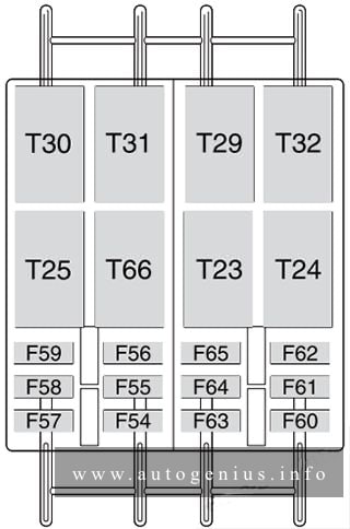
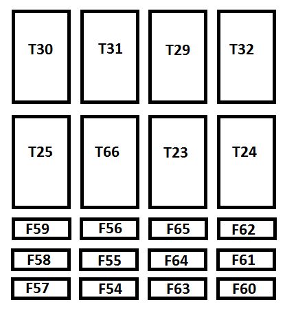
Assignment of the fuses in the passenger compartment (optional fuse box)
| № | Ampere rating [A] | Device protected |
|---|---|---|
| F54 | — | — |
| F55 | 15 | Heated seats |
| F56 | 15 | Rear passenger power socket |
| F57 | 10 | Additional heater under the seat |
| F58 | 10 | Left heated rear window |
| F59 | 7,5 | Right heated rear window |
| F60 | — | — |
| F61 | — | — |
| F62 | — | — |
| F63 | 10 | Additional passenger heater control |
| F64 | — | — |
| F65 | 30 | Additional passenger heater fan |
Engine compartment
Fuse box diagram
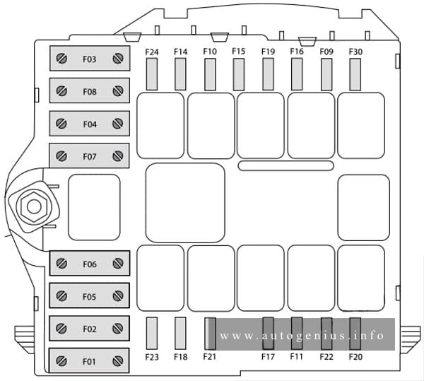
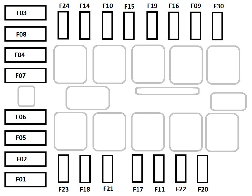
Assignment of the fuses in the engine compartment
| № | Ampere rating [A] | Device protected |
|---|---|---|
| F03 | 30 | Ignition switch (+battery) |
| F04 | 40 | Heated filter |
| F05 | 20/50 | Vaporiser for Puma engine/Passenger compartment ventilation with Webasto, robotised gearbox pump (+battery) |
| F06 | 40/60 | Engine cooling high speed fan (+battery) |
| F07 | 40/50/60 | Engine cooling low speed fan (+battery) |
| F08 | 40 | Passenger compartment fan (+key |
| F09 | 15 | Rear power socket (+battery) |
| F10 | 15 | Horn |
| F14 | 15 | Power socket (+battery) |
| F15 | 15 | Cigar lighter (+battery) |
| F18 | 7,5 | Powertrain Control Module, robotised gearbox control unit (+battery) |
| F19 | 7,5 | Air conditioning compressor |
| F20 | 30 | Windscreen wiper |
| F24 | 7,5 | Auxiliary control panel for mirror movement and folding (+key) |
| F30 | 15 | Mirrors demisting |
WARNING: Terminal and harness assignments for individual connectors will vary depending on vehicle equipment level, model, and market.