Toyota Yaris Sedan mk2 (2008) – fuse box diagram
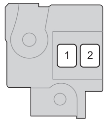
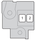
Engine compartment (type A)
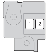
| Fuse | Ampere rating [A] | Circuit | |
| 1 | ALT | 120 | Charging system, HTR SUB2, EPS, ABS1/VSC1, HTR, ABS2/ VSC2, HTR SUB1,RDI, DEF, FR FOG, OBD2, D/L, POWER, RR DOOR, RL DOOR, STOP and AM1 |
| 2 | MAIN | 60 | EFI, HORN, AM2, ALT-S, DOME, ST, ECU-B, ETCS, HAZ, H-LP LH/ H-LP LO LH and H-LP RH/H-LP LO RH fuses |
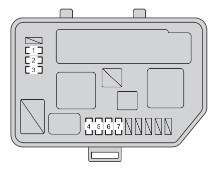
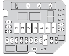
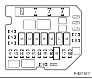
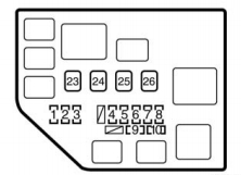
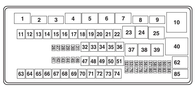
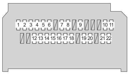
Engine compartment (type B)

| Fuse | Ampere rating [A] | Circuit | |
| 1 | AM2 | 15 | Starting system, multiport fuel injection system/sequential multiport fuel injection system |
| 2 | HORN | 10 | Horn |
| 3 | EFI | 20 | Multiport fuel injection system/ sequential multiport fuel injection system |
| 4 | SPARE | 30 | Spare fuse |
| 5 | SPARE | 15 | Spare fuse |
| 6 | SPARE | 10 | Spare fuse |
| 7 | FR DEF | 20 | No circuit |
| 8 | ABS2/VSC2 | 30 | Anti-lock brake system |
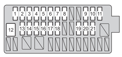
| 9 | H-LP MAIN | 30 | H-LP LH/H-LP LO LH fuse |
| 10 | ST | 30 | Starting system |
| 11 | S-LOCK | 20 | No circuit |
| 12 | DOME | 15 | Interior light, personal lights, theft deterrent system, audio system, wireless remote control system |
| 13 | ECU-B | 7,5 | Engine immobilizer system, daytime running light system, front passenger occupant classification system, power windows, door lock system, theft deterrent system, meter and gauge |
| 14 | ALT-S | 7,5 | Charging system |
| 15 | ETCS | 10 | Multiport fuel injection system/ sequential multiport fuel injection system, electronic throttle control system |
| 16 | HAZ | 10 | Turn signal lights, emergency flashers |
| 17 | H-LP RH/H-LP LO RH | 10 | Right-hand headlight |
| 18 | H-LP LH/H-LP LO LH | 10 | Left-hand headlight |
| 19 | EFI2 | 10 | Multiport fuel injection system/ sequential multiport fuel injection system |
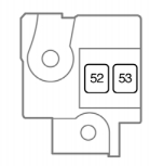
| 20 | HTR SUB2 | 40 | Air conditioning system |
| 21 | EPS | 50 | Electric power steering system |
| 22 | ABS1/VSC1 | 50 | Anti-lock brake system |
| 23 | HTR | 40 | Air conditioning system |
| 24 | RDI | 30 | Electric cooling fan |
| 25 | HTR SUB1 | 30 | Air conditioning system |
| 26 | H-LP CLN/PWR HTR | 30 | No circuit |
| 27 | AMT | 50 | No circuit |
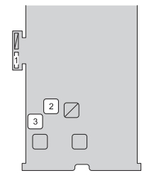
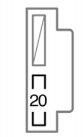
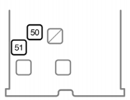
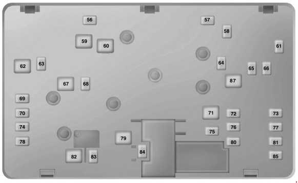
Under the instrument panel (type A)
| Fuse | Ampere rating [A] | Circuit | |
| 1 | ACC2 | 7,5 | Shift lock system |
| 2 | DEF | 30 | Rear window defogger |
| 3 | POWER | 30 | Power windows |
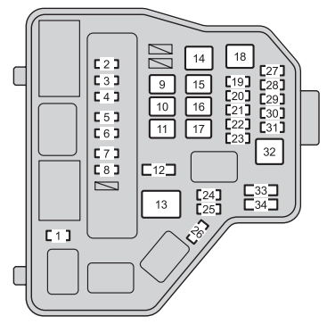
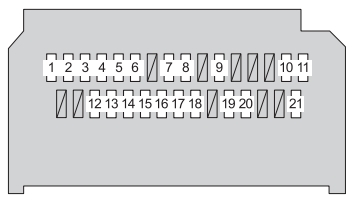
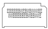
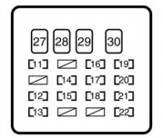
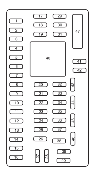
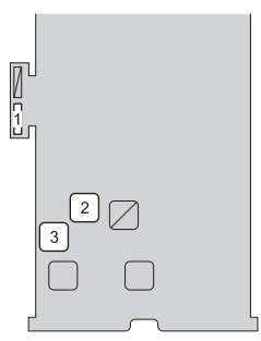
Under the instrument panel (type B)
| Fuse | Ampere rating [A] | Circuit | |
| 1 | TAIL* | 10 | Side marker lights, parking lights, tail lights, license plate lights, multiport fuel injection system/sequential multiport fuel injection system |
| PANEL 2* | 7,5 | Side marker lights, parking lights, tail lights, license plate lights | |
| 2 | PANEL 1 | 7,5 | Illuminations, instrument panel light control, meter and gauge |
| 3 | A/C | 7,5 | Rear window defogger, air conditioning system |
| 4 | D DOOR | 20 | Power windows |
| 5 | RL DOOR | 20 | Rear passenger’s power window (left side) |
| 6 | RR DOOR | 20 | Rear passenger’s power window (right side) |
| 7 | CIG | 15 | Power outlet |
| 8 | ACC | 7,5 | Door lock system, outside rear view mirrors, audio system |
| 9 | ID/UP/MIR HTR | 10 | Multiport fuel injection system/ sequential multiport fuel injection system |
| 10 | IGN | 7,5 | Multiport fuel injection system/ sequential multiport fuel injection system, engine immobilizer system, SRS airbag system, front passenger occupant classification system |
| 11 | MET | 7,5 | Meter and gauge |
| 12 | WIP | 25 | Windshield wiper and washer |
| 13 | RR WIP | 15 | No circuit |
| 14 | WISH | 15 | Windshield wiper and washer |
| 15 | ECU-IG | 10 | Daytime running light system, antilock brake system, electric power steering system, power windows, door lock system, theft deterrent system, electric cooling fan, meter and gauge |
| 16 | GAUGE | 10 | Charging system, turn signal lights, emergency flashers, back-up lights, instrument panel light control, shift lock system, rear window defogger, air conditioning system, automatic transmission system |
| 17 | OBD2 | 7,5 | On-board diagnosis system |
| 18 | STOP | 10 | Stop lights, high mounted stoplight, multiport fuel injection system/sequential multiport fuel injection system, shift lock system, anti-lock brake system |
| 19 | D/L | 25 | Door lock system |
| 20 | FR FOG | 15 | Front fog lights |
| 21 | TAIL | 10 | Side marker lights, parking lights, tail lights, license plate lights, multiport fuel injection system/sequential multiport fuel injection system |
| 22 | AM1 | 25 | Multiport fuel injection system/ sequential multiport fuel injection system |
WARNING: Terminal and harness assignments for individual connectors will vary depending on vehicle equipment level, model, and market.