BYD Seal (2022 – 2023) – fuse box diagram
Year of production: 2022, 2023
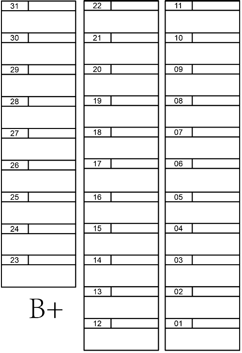
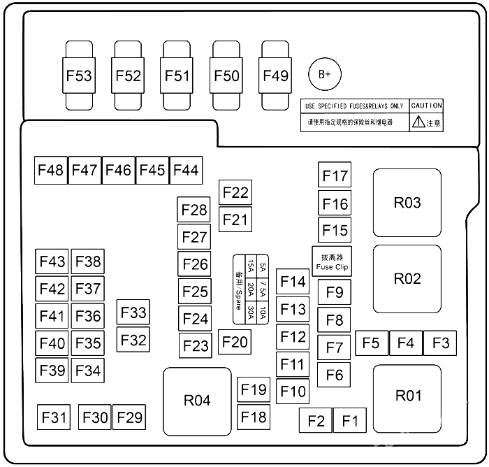
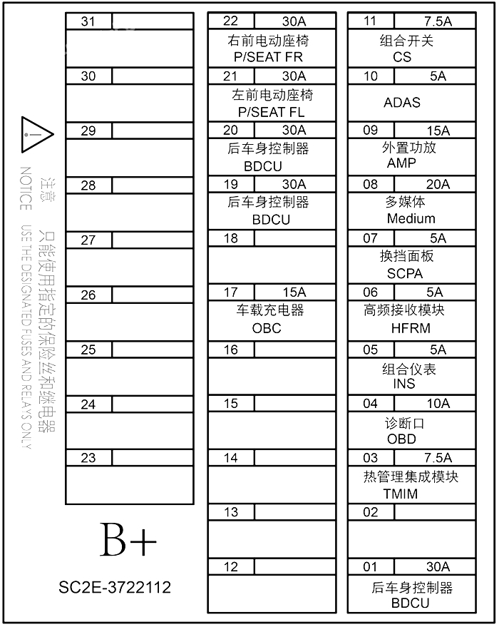
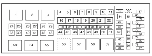
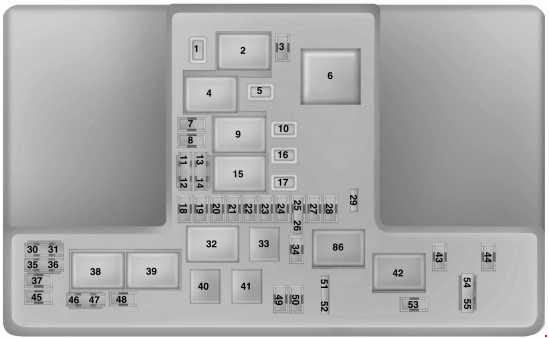
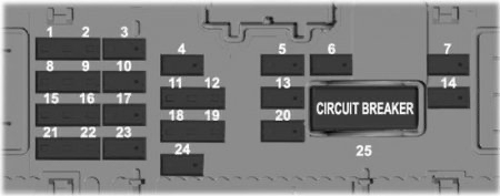
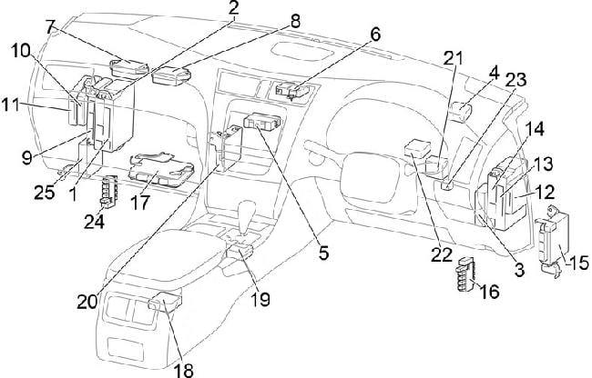
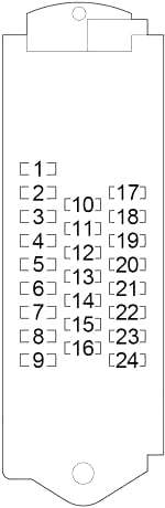
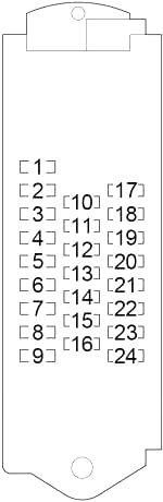
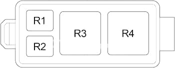
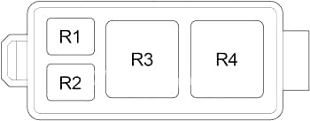
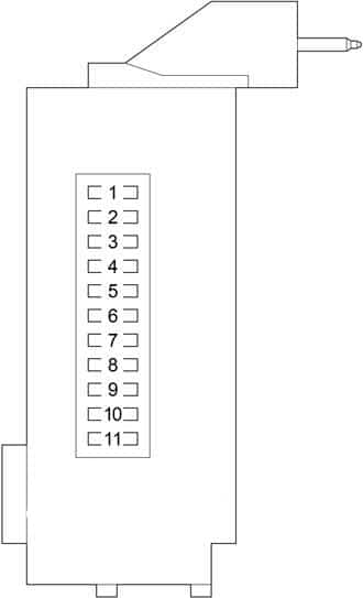
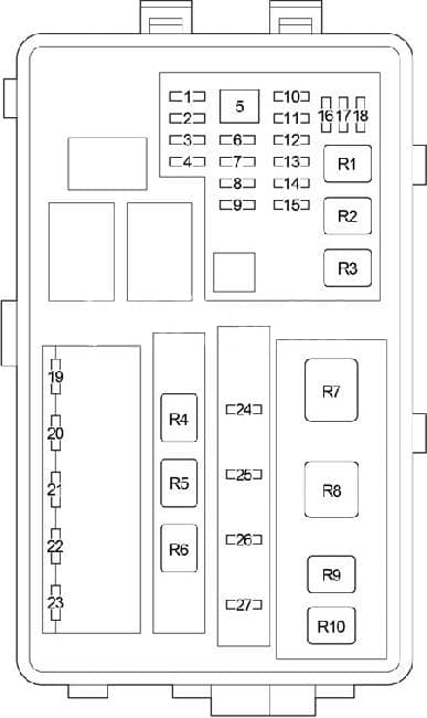
Instrument panel fuse box
The dashboard panel fuses are located under the driver side of the dashboard.

| № | Amps | Protected Component or Circuit | Warning Labels |
|---|---|---|---|
| 01 | 30A | Rear body controller | BDCU |
| 02 | 30A | Rear body controller | BDCU |
| 03 | 10A | Wireless charger | CW Charge |
| 04 | 10A | Diagnosis port | OBD |
| 05 | 7.5A | HUD | HUD |
| 06 | 5A | High-frequency receiving module | HFRM |
| 07 | 5A | Gearshift panel | SCPA |
| 08 | 20A/15A | Infotainment system | Medium |
| 09 | 5A | Brake light switch | STOP SW |
| 10 | 30A | Rear body controller | BDCU |
| 11 | 7.5A | Combination switch | CS |
| 12 | 30A | Constant power | Bat |
| 13 | 25A | External amplifier | AMP |
| 14 | 30A | Intelligent driving | IDSDC |
| 15 | 30A | Intelligent driving | IDSDC |
| 16 | 15A | HV all-in-one controller | PDC |
| 17 | 15A | HV all-in-one controller | PDC |
| 18 | 15A/25A | Suspension module | DiSus |
| 19 | 25A | Front left window | FL Door |
| 20 | 25A | Front right window | FR Door |
| 21 | 25A | Rear left window | RL Door |
| 22 | 25A | Rear right window | RR Door |
| 23 | 15A | CCS communication converter | CCS |
| 24 | 10A | Alcohol interlock | Alcohol interlock |
| 25 | 7.5A | E-Call | E-Call |
| 26 | – | – | – |
| 27 | – | – | – |
| 28 | – | – | – |
| 29 | – | – | – |
| 30 | – | – | – |
| 31 | – | – | – |
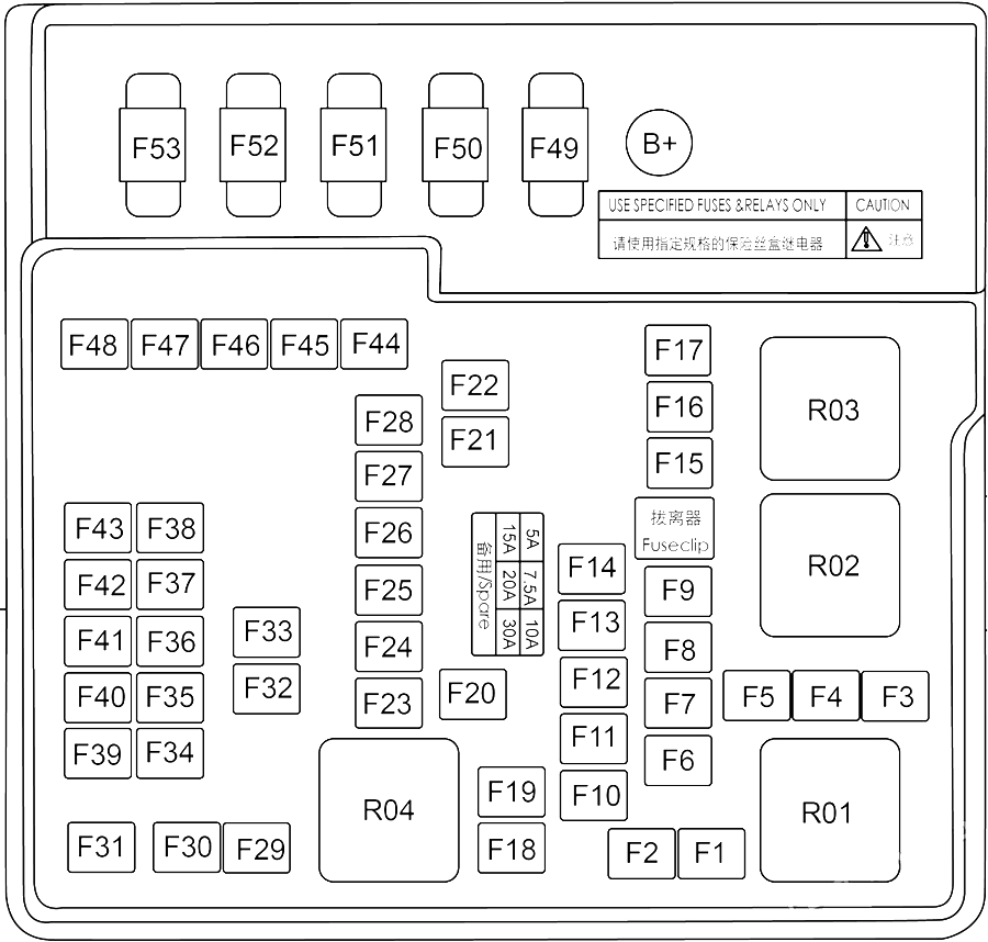
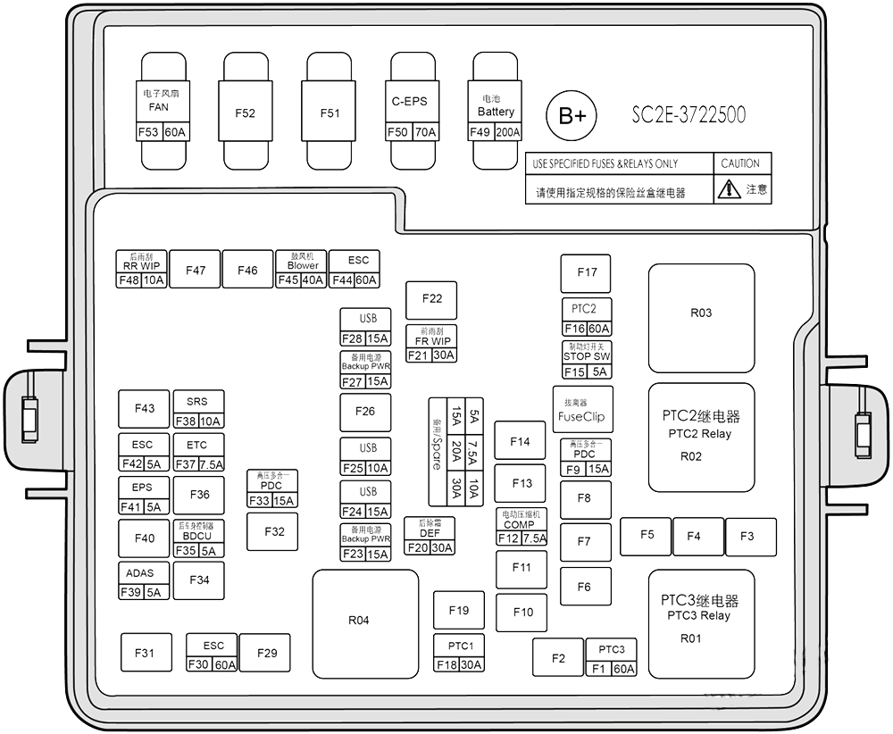
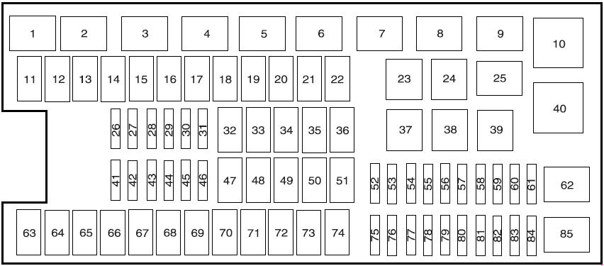
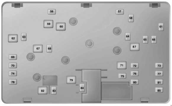
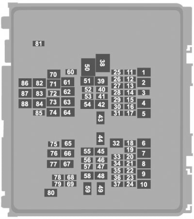
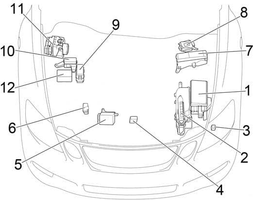
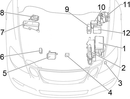
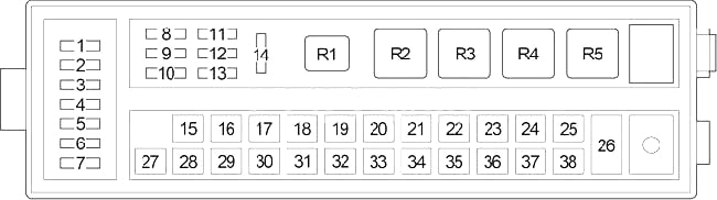
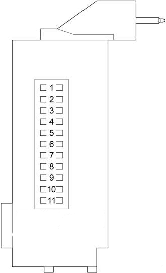
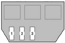
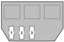
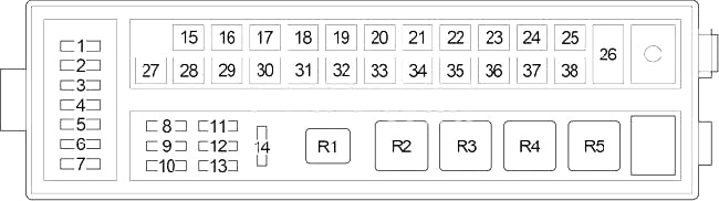
Engine Compartment Fuse Box
The fuse under the hood is located on the rear left side of the motor compartment.

| № | Amps | Protected Component or Circuit |
|---|---|---|
| F1 | – | – |
| F2 | 25A | External amplifier |
| F3 | – | – |
| F4 | – | – |
| F5 | – | – |
| F6 | – | – |
| F7 | – | – |
| F8 | – | – |
| F9 | 7.5A | Battery manager |
| F10 | 15A | Electrically controlled cooling water pump |
| F11 | 10A | Electrically controlled cooling water pump |
| F12 | – | – |
| F13 | – | – |
| F14 | – | – |
| F15 | 10A | ADAS |
| F16 | 40A | Low speed fan |
| F17 | – | – |
| F18 | – | – |
| F19 | – | – |
| F20 | 20A | Trailer controller |
| F21 | 30A | Front wiper |
| F22 | 30A | Rear windshield defroster |
| F23 | 20A | Rear electronic fuel pump |
| F24 | 10A | Compressor |
| F25 | 10A | Motor controller |
| F26 | 7.5A | E-Call |
| F27 | 15A | Auxiliary power |
| F28 | 15A | USB |
| F29 | 30A | Left front electric seat |
| F30 | 60A | ESC |
| F31 | 20A | Front electronic fuel pump |
| F32 | 30A | Right front electric seat |
| F33 | 10A | Integrated thermal management module |
| F34 | 15A | Heater |
| F35 | 5A | Rear body controller |
| F36 | 10A | ADAS |
| F37 | 7.5A | ADAS |
| F38 | 10A | SRS |
| F39 | – | – |
| F40 | 7.5A | ETC |
| F41 | 5A | EPS |
| F42 | 5A | ESC |
| F43 | 7.5A | Suspension module |
| F44 | 60A | ESC |
| F45 | 40A | Blower |
| F46 | 15A | USB |
| F47 | – | – |
| F48 | – | – |
| F49 | 125A | DP-EPS |
| F50 | – | – |
| F51 | 60A | Electric fan |
| F52 | – | – |
| F53 | – | – |
WARNING: Terminal and harness assignments for individual connectors will vary depending on vehicle equipment level, model, and market.