BYD Seal (2022 – 2024) – fuse and relay box diagram
Year of production: 2022, 2023, 2024
This article provides fuse box diagrams for the 2022 and 2023 BYD Seal models, details the location of the fuse panels within the vehicle, and explains the function of each fuse (fuse layout).
Instrument panel fuse box
Fuse Box Location
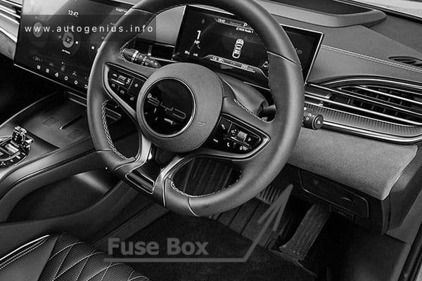
The dashboard panel fuses are located under the driver side of the dashboard.
Fuse Box Diagram
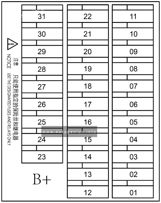
Assignment of the fuses in the instrument panel
| № | Amps | Protected Component or Circuit | Warning Labels |
|---|---|---|---|
| 01 | 30A | Rear body controller | BDCU |
| 02 | 30A | Rear body controller | BDCU |
| 03 | 10A | Wireless charger | CW Charge |
| 04 | 10A | Diagnosis port | OBD |
| 05 | 7.5A | HUD | HUD |
| 06 | 5A | High-frequency receiving module | HFRM |
| 07 | 5A | Gearshift panel | SCPA |
| 08 | 20A/15A | Infotainment system | Medium |
| 09 | 5A | Brake light switch | STOP SW |
| 10 | 30A | Rear body controller | BDCU |
| 11 | 7.5A | Combination switch | CS |
| 12 | 30A | Constant power | Bat |
| 13 | 25A | External amplifier | AMP |
| 14 | 30A | Intelligent driving | IDSDC |
| 15 | 30A | Intelligent driving | IDSDC |
| 16 | 15A | HV all-in-one controller | PDC |
| 17 | 15A | HV all-in-one controller | PDC |
| 18 | 15A/25A | Suspension module | DiSus |
| 19 | 25A | Front left window | FL Door |
| 20 | 25A | Front right window | FR Door |
| 21 | 25A | Rear left window | RL Door |
| 22 | 25A | Rear right window | RR Door |
| 23 | 15A | CCS communication converter | CCS |
| 24 | 10A | Alcohol interlock | Alcohol interlock |
| 25 | 7.5A | E-Call | E-Call |
| 26 | – | – | – |
| 27 | – | – | – |
| 28 | – | – | – |
| 29 | – | – | – |
| 30 | – | – | – |
| 31 | – | – | – |
Engine Compartment Fuse Box
Fuse Box Location
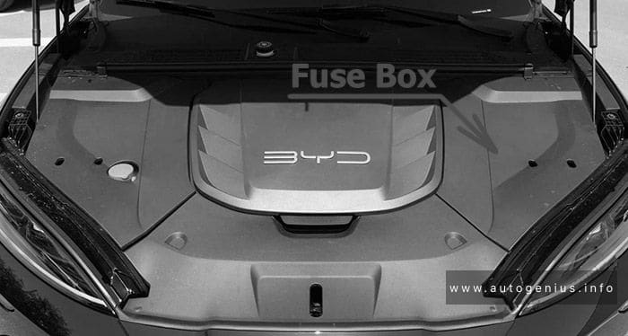
The fuse under the hood is located on the rear left side of the motor compartment.
Fuse Box Diagram
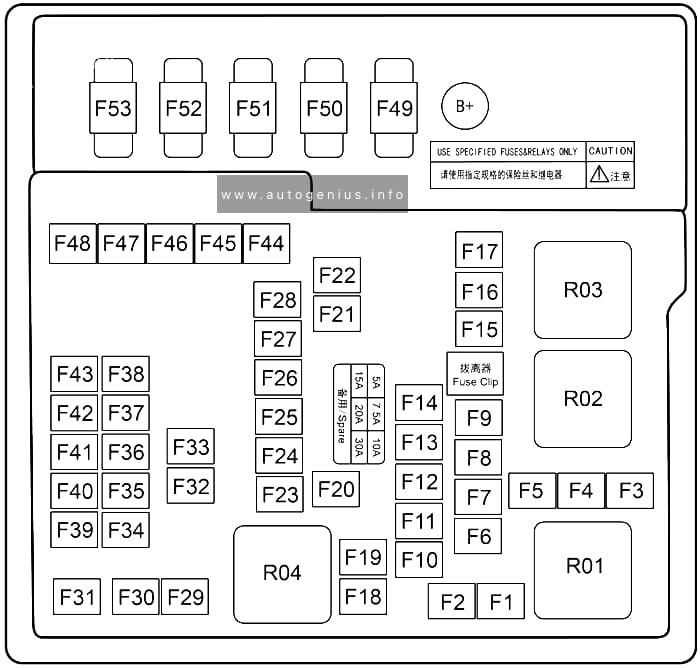
Assignment of the fuses in the engine compartment
| № | Amps | Protected Component or Circuit |
|---|---|---|
| F1 | – | – |
| F2 | 25A | External amplifier |
| F3 | – | – |
| F4 | – | – |
| F5 | – | – |
| F6 | – | – |
| F7 | – | – |
| F8 | – | – |
| F9 | 7.5A | Battery manager |
| F10 | 15A | Electrically controlled cooling water pump |
| F11 | 10A | Electrically controlled cooling water pump |
| F12 | – | – |
| F13 | – | – |
| F14 | – | – |
| F15 | 10A | ADAS |
| F16 | 40A | Low speed fan |
| F17 | – | – |
| F18 | – | – |
| F19 | – | – |
| F20 | 20A | Trailer controller |
| F21 | 30A | Front wiper |
| F22 | 30A | Rear windshield defroster |
| F23 | 20A | Rear electronic fuel pump |
| F24 | 10A | Compressor |
| F25 | 10A | Motor controller |
| F26 | 7.5A | E-Call |
| F27 | 15A | Auxiliary power |
| F28 | 15A | USB |
| F29 | 30A | Left front electric seat |
| F30 | 60A | ESC |
| F31 | 20A | Front electronic fuel pump |
| F32 | 30A | Right front electric seat |
| F33 | 10A | Integrated thermal management module |
| F34 | 15A | Heater |
| F35 | 5A | Rear body controller |
| F36 | 10A | ADAS |
| F37 | 7.5A | ADAS |
| F38 | 10A | SRS |
| F39 | – | – |
| F40 | 7.5A | ETC |
| F41 | 5A | EPS |
| F42 | 5A | ESC |
| F43 | 7.5A | Suspension module |
| F44 | 60A | ESC |
| F45 | 40A | Blower |
| F46 | 15A | USB |
| F47 | – | – |
| F48 | – | – |
| F49 | 125A | DP-EPS |
| F50 | – | – |
| F51 | 60A | Electric fan |
| F52 | – | – |
| F53 | – | – |
WARNING: Terminal and harness assignments for individual connectors will vary depending on vehicle equipment level, model, and market.