Cadillac Seville (1980 – 1985) – fuse box diagram
Year of production: 1980, 1981, 1982, 1983, 1984, 1985
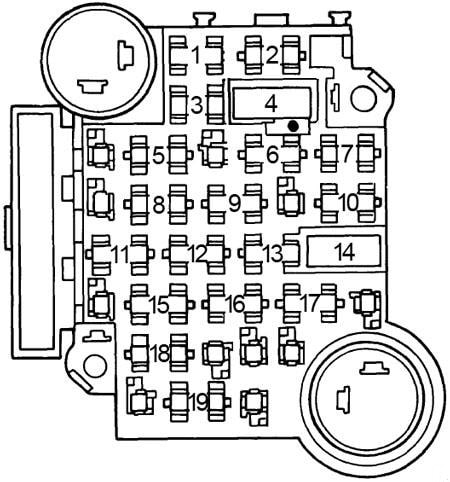
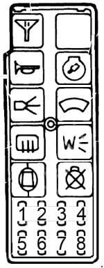
Fuse box diagram

| Fuse | [A] | Protected Component |
| 1 | 10 | Front side marker, cornering and ash tray lights |
| 2 | 3 | Cruise control and DFI brake switch |
| 3 | 5 | Rheostat controlled instrument panel lights |
| 4 | — | — |
| 5 | 10 | Back-up lights, diesel fast idle, diesel controller |
| 6 | 20 | Air conditioning compressor feed, ECC programmer and power module, rear defogger relay coil and generator indicator |
| 7 | 10 | Antenna motor feed |
| 8 | 20 | Turn signal lights |
| 9 | 25 | Opera, license, tail and rear side marker lights |
| 10 | 20 | Stop light switch, hazard warning flasher and ECC control head |
| 11 | 20 | Fuel gauge, oil pressure and coolant temperature indicator, low brake fluid indicator, seat belt warning chime and indicator and electronic level control compressor |
| 12 | 20 | Key warning buzzer, coolant temperature indicator, instrument panel courtesy and compartment lights and cigar lighter |
| 13 | — | — |
| 14 | — | — |
| 15 | 10 | Radio and antenna relay coil |
| 16 | — | — |
| 17 | 20 | Body courtesy and ash tray lights, electronic level control height sensor |
| 18 | 25 | Windshield wipers and low washer fluid indicator |
| 19 | 25 | Rear window defogger |
| Fuse | [A] | Protected Component |
| 1 | 3 | Fuel injector |
| 2 | 3 | Fuel injector |
| 3 | 3 | Fuel pump cranking circuit |
| 4 | 20 | ECS battery |
| 5 | 10 | MDA ignition |
| 6 | 10 | Fuel pump |
| 7 | 15 | ECS ignition |
| 8 | — | — |
Circuit Breaker:
Headlights (Twilight Sentinel) — Integral with headlight switch.
Windshield Wiper — Integral with windshield wiper switch.
Rear Defogger — Circuit breaker located on lower steering column cover reinforcement.
Fusible Link:
All models are equipped with fusible links which attach to lower ends of main feed wires at junction block, or at starter solenoid. Gauge size is marked on insulation and each link is four sizes smaller than the cable it is designed to protect. The same size wire with special hypalon insulation must be used when replacing a fusible link.
In-Line Fuse:
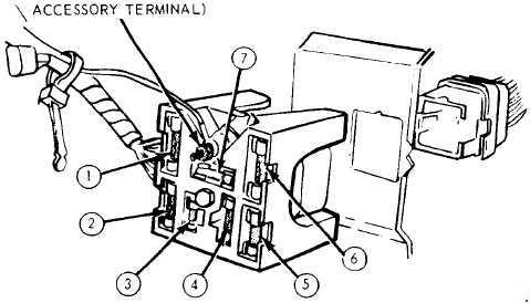
Vanity Mirror — 2 amp. fuse located behind mirror.
Theft Deterrent – One 20 amp. fuse for lights, and one 25 amp. fuse for horn is located above radio in instrument panel.
Trunk Lid Pull Down — One 20 amp. fuse is located behind right hand fabric rear end panel inside trunk.
WARNING: Terminal and harness assignments for individual connectors will vary depending on vehicle equipment level, model, and market.