Chevrolet Silverado mk4 (Fourth Generation) (2019 – 2022) – fuse box diagram

Chevrolet Silverado mk4 (Fourth Generation) (2019 – 2022) – fuse box diagram

Year of production: 2019, 2020, 2021, 2022

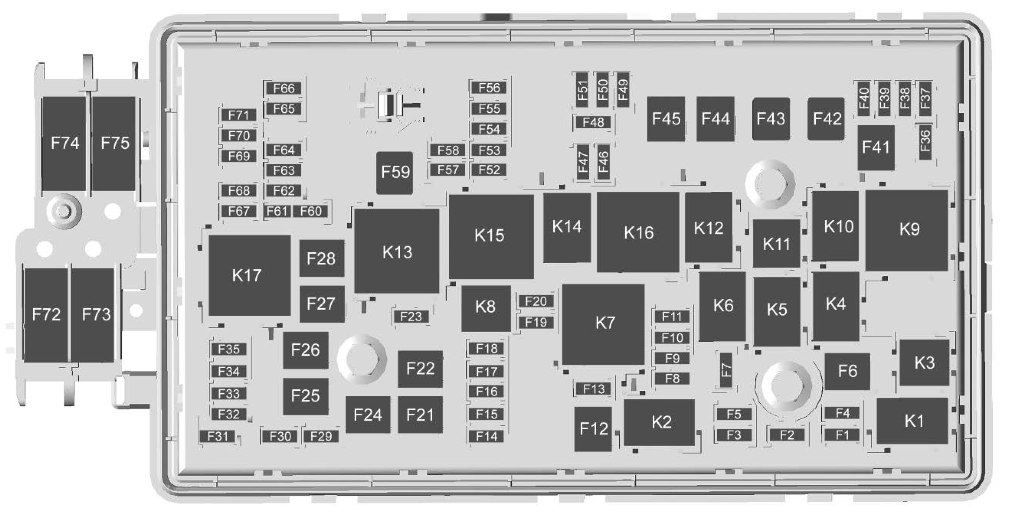
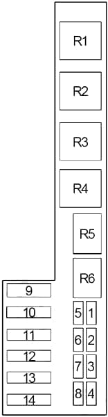
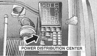
Engine Compartment Fuse Block
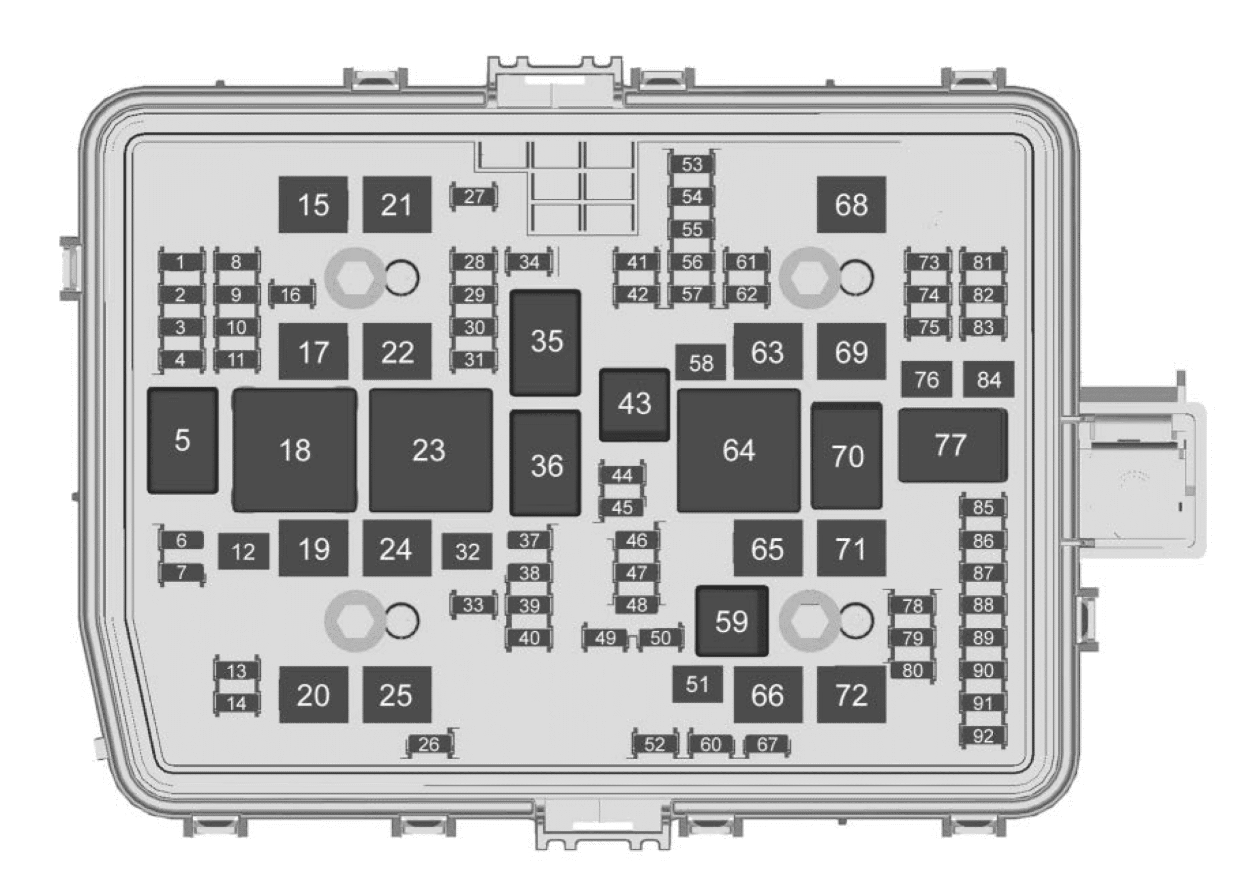
Chevrolet Silverado mk4 - fuse box diagram - engine compartment
Chevrolet Silverado mk4 – fuse box diagram – engine compartment
Fuses Usage
1 High-beam left
2 High-beam right
3 Headlamp left
4 Headlamp right
6 2019-2021: TIM
7
8 Fog lamp
9 2019-2020: VKM
10
11 Police upfitter
12
13 Washer front
14 Washer rear
15 2019-2021: MSB driver
16
17 IECL 1
19 DC/AC inverter
20 2019: IECR 2.
2020-2022: IECR 2 (LD) / EBCM2 (HD)
21 2019-2021: MSB pass
22 IECL 2
24 Eboost 1 / EBCM 1
25 2019-2021: REC
26
27 Horn
28
29
30
31
32 Rear window defogger
33 Heated mirror
34 Parking lamp left
37 2019-2021: Euro trailer
38 2019-2021: TIM
39
40 Misc ignition
41 Trailer parking lamp
42 Park lamp right
44
45 2019-2021: Second fuel pump
46 Engine control module ignition
47 Transmission control module ignition
48
49 Transmission control module
50 A/C clutch
51 Transfer case control module
52 Front wiper
53 Center high-mounted stop lamp
54 Trailer reverse lamp
55 Trailer back-up lamp
56 SADS
57 TTPM/SBZA
58 2019: Starter motor.
2020-2022: Starter motor (LD & HD DSL)
60 Active fuel management 1
61 VES
62 Integrated chassis control module/CVS
63 Trailer battery
65 Auxiliary underhood electrical center
66 Cooling fan motor left
67 Active fuel management 2
68
69 2019: Starter pinion.
2020-2022: Starter Pinion (LD) / Starter Motor (HD Gas)
71 Cooling fan
72 Cooling fan right
73 Trailer stop/turn lamp left
74 2019-2021: TIM
2022: Trailer Interface Module 1
75 DEFC
76 Electric RNG BDS
78 Engine control module
79 Auxiliary battery
80 Cabin cooling pump
81 Trailer stop/turn lamp right
82 2019-2021: TIM
2022: Trailer Interface Module 2
83 FTZM
84 Trailer brake
85 ENG
86 Engine control module
87 Injector B even
88 O2 B sensor
89 O2 A sensor
90 Injector A odd
91 Engine control module throttle control
92 2019-2021: Cool fan clutch
2022: Cool fan clutch/ Aeroshutter
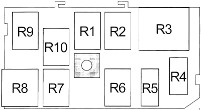


Relays Usage
5 Headlamp
18 DC/AC inverter
23 Rear window defogger
35 Parking lamp
36 Run/Crank
43 2019-2021: Second fuel pump
59 A/C clutch
64 2019: Starter motor.
2020-2021: Starter Motor (LD & HD DSL) / Cool Fan Clutch (HD Gas)
2022: Starter Motor (LD & HD DSL)
70 2019: Starter pinion.
2020-2022: Starter Pinion (LD) / Starter Motor (HD Gas)
77 Powertrain


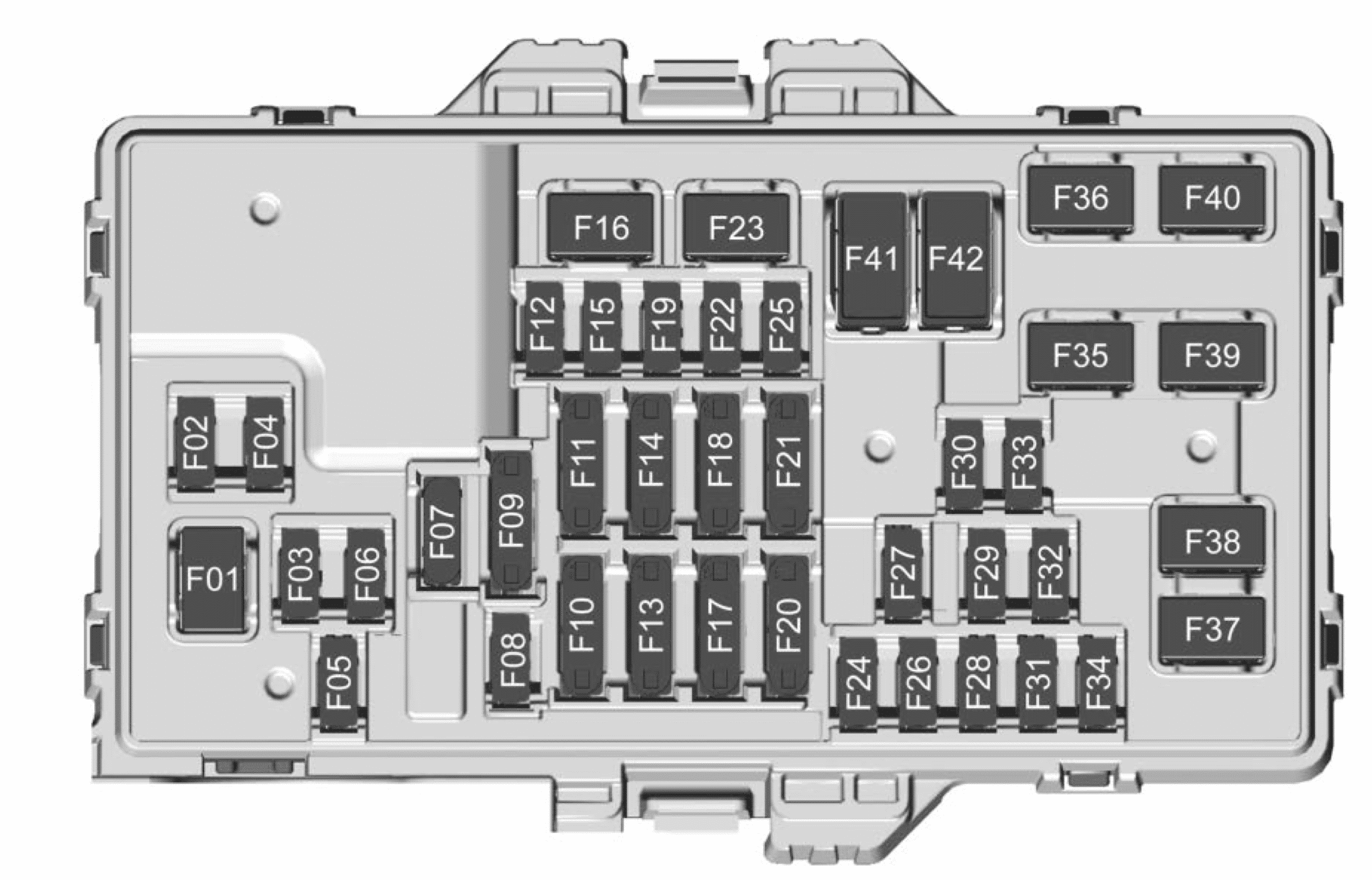
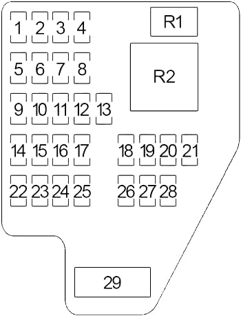
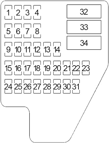
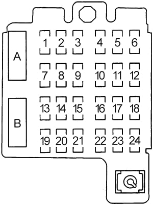
Instrument Panel Fuse Block (left side)
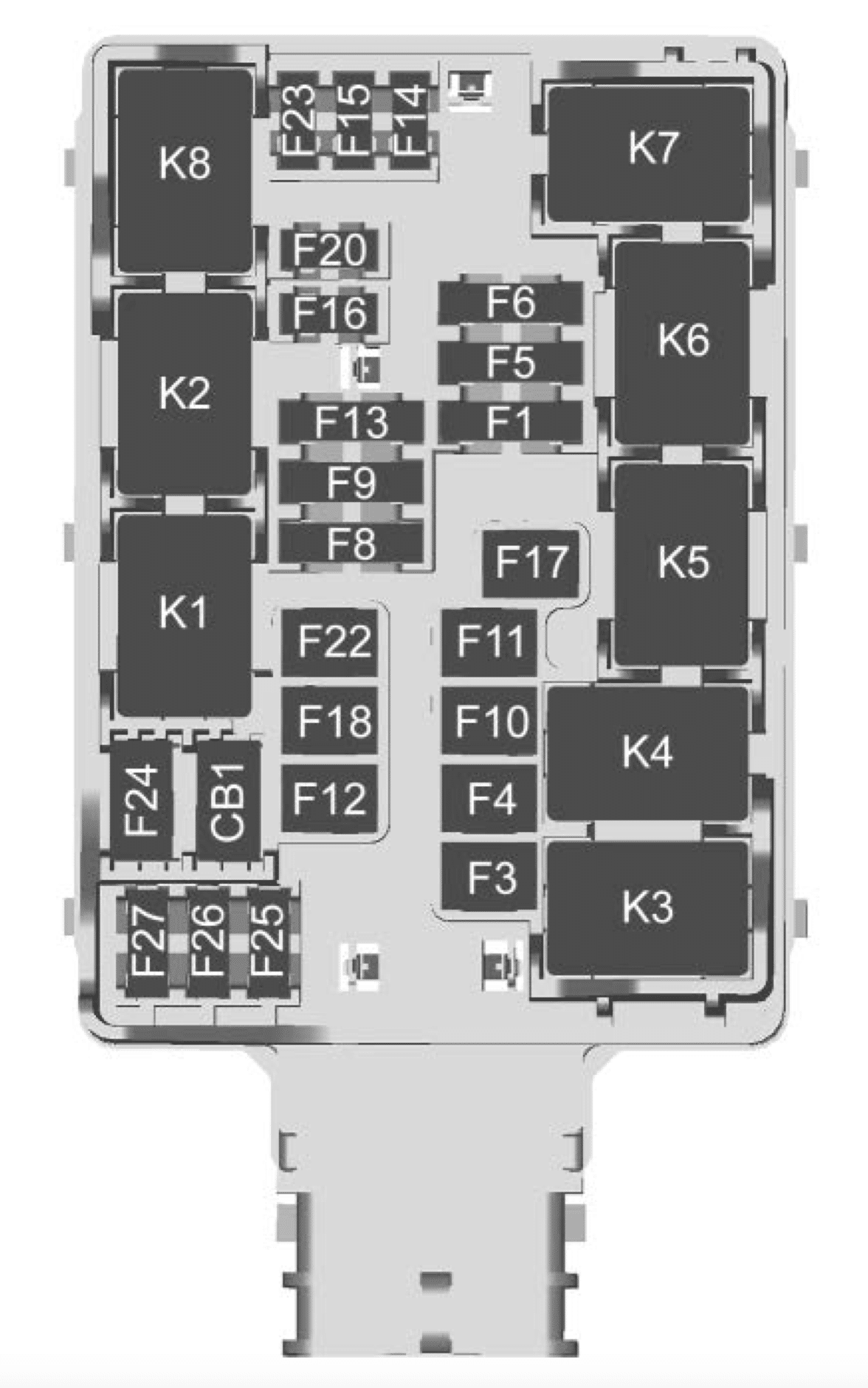
Chevrolet Silverado mk4 - fuse box diagram - instrument panel (left side)
Chevrolet Silverado mk4 – fuse box diagram – instrument panel (left side)
Number Usage
F1 Rear heated seats left/right
F3 2019-2020: Euro trailer
F4
F5 2019-2020: Front Bolster
2021-2022: Spare/MFEG (Multifunction End Gate)
F6 Heated and cooled seats left/right
F8 2019-2020: Rear seat entertainment/ Theft deterrent
F9 Passive entry/Passive start/Driver seat module
F10
F11 2019-2020: Sunshade
F12 Passenger power seat
F13 Export power take off/ Special equipment option 1
F14
F15
F16 Amplifier
F17 MFEG (Multifunction End Gate)
F18
F20 Endgate
F22 Rear sliding window
F23
F24
F25
F26
F27
Circuit Breakers
CB1
Relays
K1 Rear sliding window open
K2 Rear sliding window close
K3 MFEG major 1
K4 MFEG minor 1
K5 MFEG minor 2
K6 MFEG major 2
K7 2019-2020: Anti-theft
K8

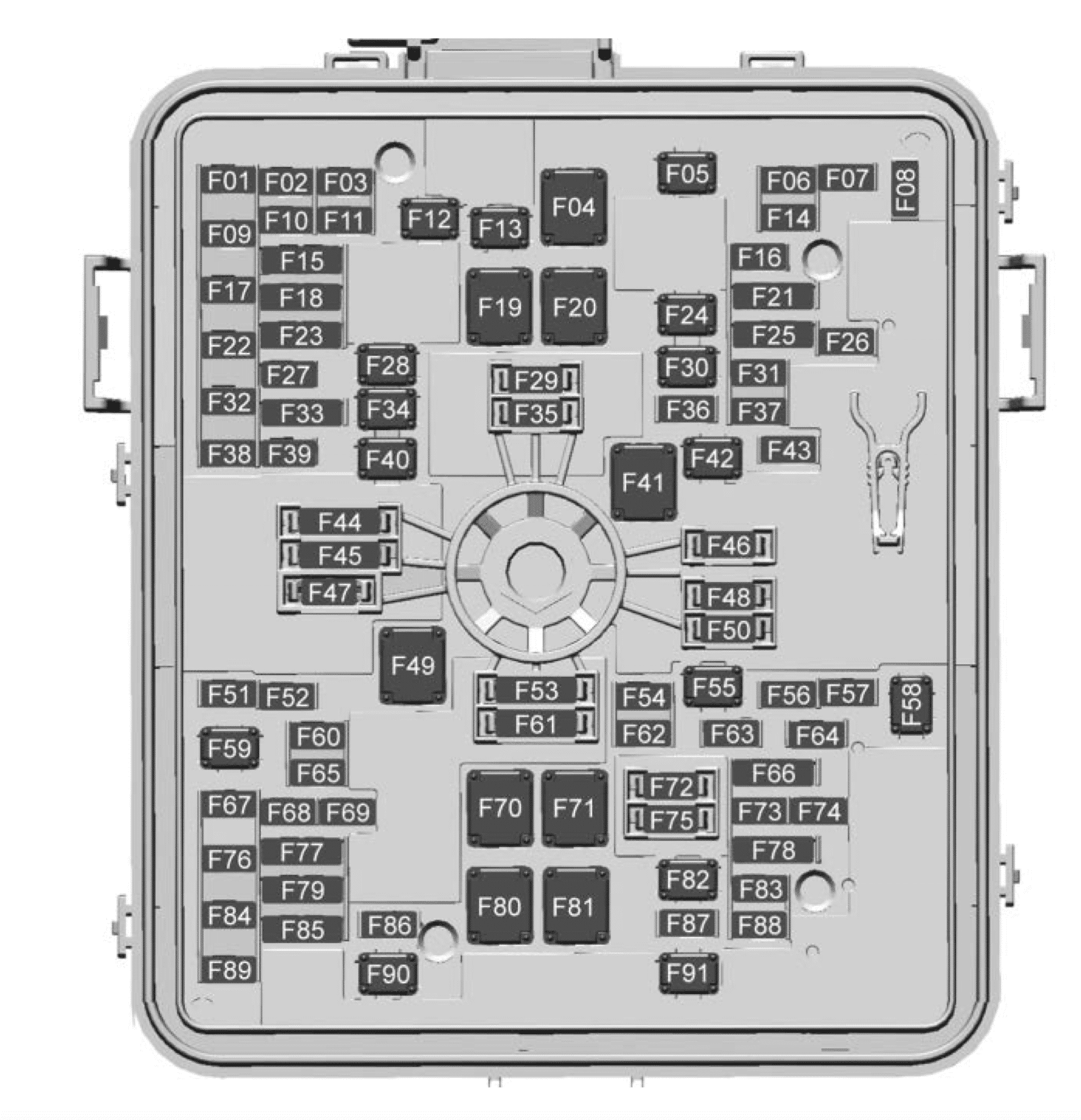
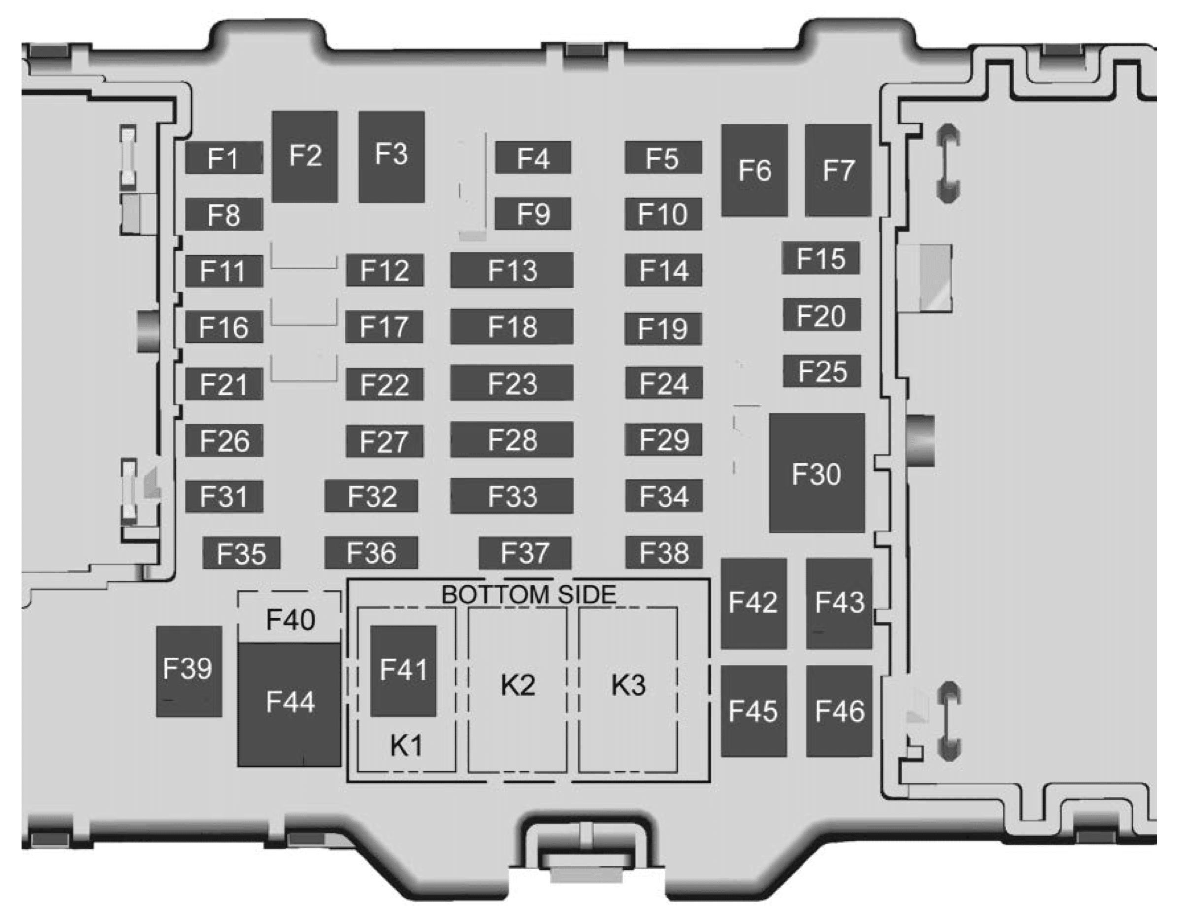
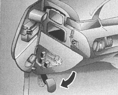
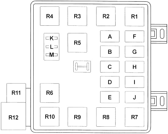
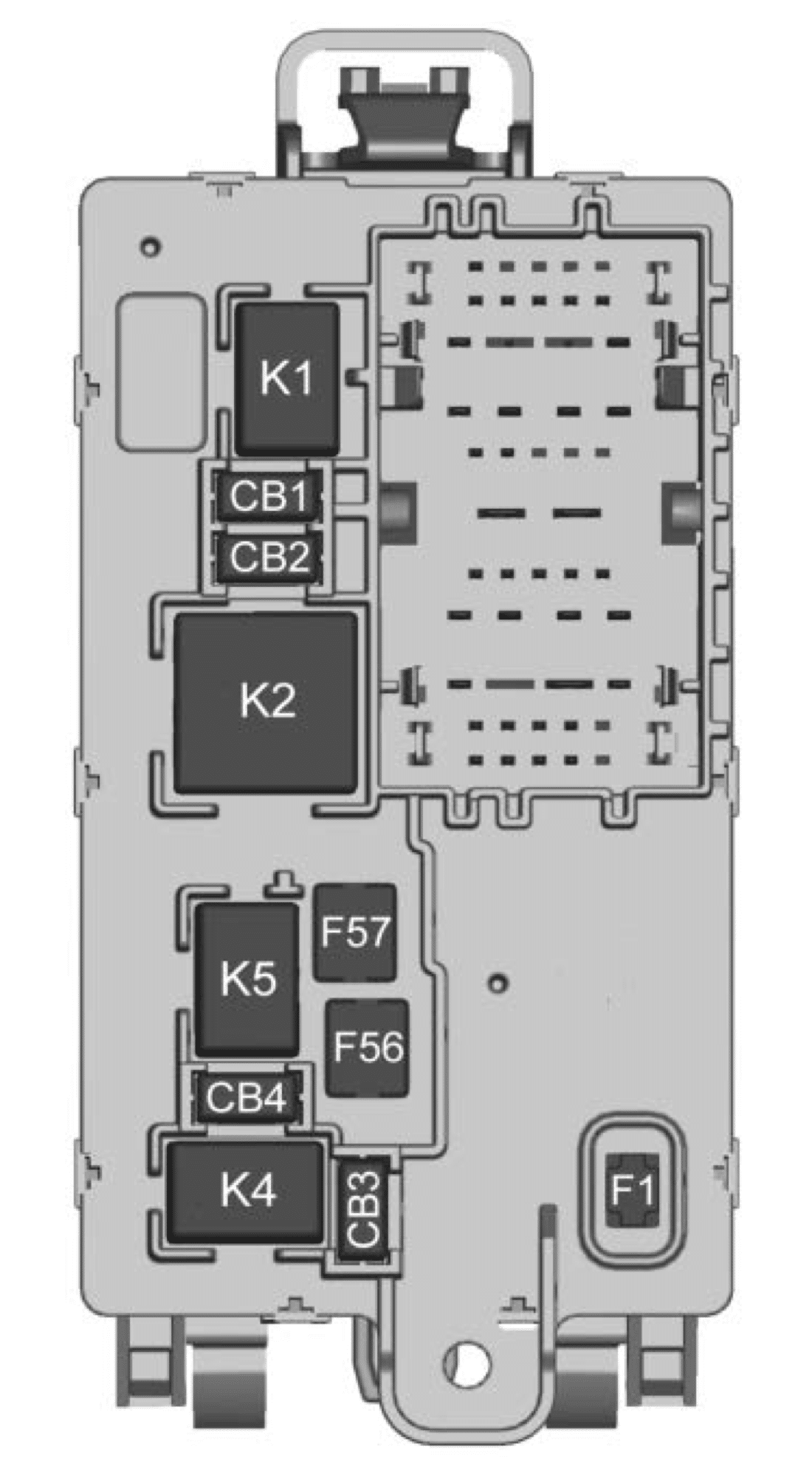
Instrument Panel Fuse Block (Right)

The right instrument panel fuse block access door is on the passenger side edge of the instrument panel.
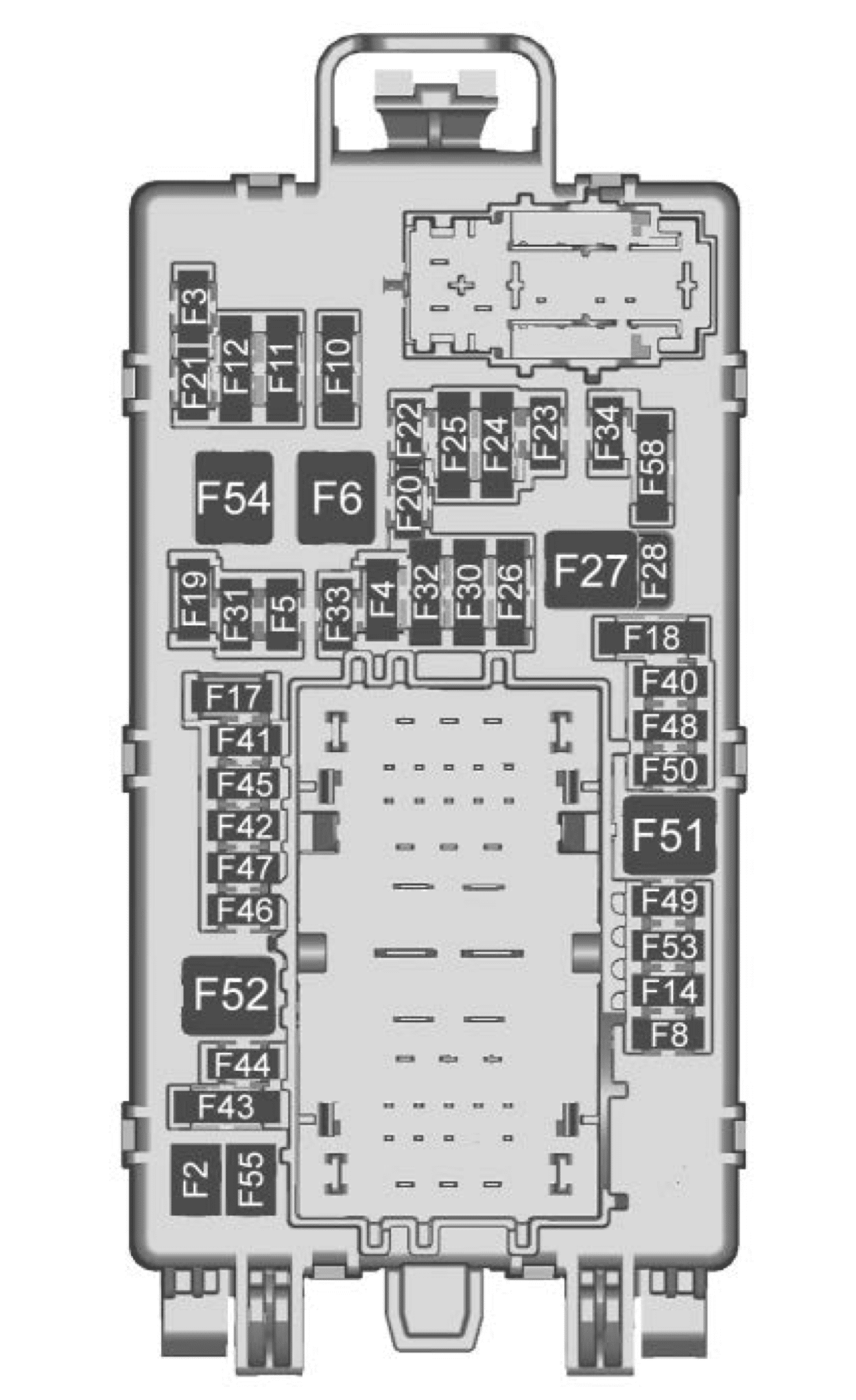
Chevrolet Silverado mk4 - fuse box diagram - instrument panel (left side - front)
Chevrolet Silverado mk4 – fuse box diagram – instrument panel (left side – front)
Chevrolet Silverado mk4 - fuse box diagram - instrument panel (left side - back)
Chevrolet Silverado mk4 – fuse box diagram – instrument panel (left side – back)
Number Usage
F1 Right doors
F2 Left doors
F3 Universal remote system
F4
F5
F6 Front blower
F8 Lumbar switch
F10 Body control module 6/ Body control module 7
F11 Seat/ Column lock module
F12 Body control module 3/Body control module 5
F14 Mirrors/Windows module
F17 Steering wheel controls
F18 Video processing module/ Obstacle detection
F19 Discrete Logic Ignition Switch (DLIS)
F20 Cooled seats
F21 NOT R/C
F22 Heated steering wheel
F23 MISC R/C
F24 2019-2021: Instrument panel cluster ignition/ Overhead
2022: Power Take Off/ Reflective Light Auxiliary Display/ Instrument Panel Cluster/ Central Gateway Module/ Inside Rear View Mirror/ Overhead Console Module Ignition
F25 Heating, ventilation, and air conditioning ignition/Heating, ventilation, and air conditioning auxiliary
F26 USB ports/Special equipment option retained accessory power
F27 Accessory power outlet/retained accessory power
F28 Accessory power outlet/Battery
F30 Sensing and diagnostic module/ Parking brake
F31 Body control module 4
F32 Special equipment option/Data link connection
F33 Body control module 8
F34 Cargo lamp
F40 Central Gateway Module (CGM)
F41 Infotainment 1
F42 Telematics Connectivity Platform (TCP)
F43
F44 2019-2021: Active vibration management (AVM)
F45 Body control module 2
F46 Heating, ventilation, and air conditioning/ Battery 1
F47 Instrument panel cluster/Battery
F48 Transmission control module
F49 Body control module 1
F50
F51 Battery 1
F52 Battery 2
F53
F54 Sunroof
F55 Driver power seat
F56 DC DC TRANS 1
F57 DC DC TRANS 2
F58 Infotainment 2
Circuit Breakers
CB1 Accessory power outlet 2
CB2 Accessory power outlet 1/ Cigarette Lighter
CB3 2019-2021: Accessory power outlet 3
CB4 2019-2021: Accessory power outlet 4
Relays
K1 Run/Crank
K2 Retained accessory power/ Accessory 1
K4 2019-2021: Retained accessory power/ Accessory 2
K5

WARNING: Terminal and harness assignments for individual connectors will vary depending on vehicle equipment level, model, and market.

Yamaha YZF-R1 2015 (2015-2019) wiring diagram

Yamaha YZF-R1 2015 (2015-2019) wiring diagram

Yamaha YZF-R1 - wiring diagrams
Yamaha YZF-R1 – wiring diagrams

YZF-R1/YZF-R1F 2015

1. ACmagneto
2. Rectifier/regulator
3. Mainswitch
4. Mainfuse
5. Radiatorfanmotorrelay
6. Hazardlightingfuse
7. Fuelinjectionsystemfuse
8. Electricthrottlevalvefuse
9. Backupfuse
10. Radiator fan motor fuse (right)
11. Radiator fan motor fuse (left)
12. Ignition fuse
13. Signaling system fuse
14. ABS ECU fuse
15. ABS solenoid fuse
16. Headlight fuse
17. Auxiliary fuse
18. Joint coupler
19. Battery
20. Engine ground
21. ABS motor fuse
22. Starter relay
23. Starter motor
24. Immobilizer unit
25. Handlebar switch (right)
26. Front brake light switch
27. Wheel switch
28. Start/engine stop switch
29. Relay unit
30. Starting circuit cut-off relay
31. Fuel pump relay
32. Neutral switch
33. Sidestand switch
34. Fuel sender
35. Fuel pump
36. Shift switch
37. ECU (Engine Control Unit)
38. Ignition coil #1
39. Ignition coil #2
40. Ignition coil #3
41. Ignition coil #4
42. Spark plug
43. Air induction system solenoid 44. Primary injector #1
45. Primary injector #2
46. Primary injector #3
47. Primary injector #4
48. Secondary injector #1
49. Secondary injector #2
50. Secondary injector #3
51. Secondary injector #4
52. Accelerator position sensor 53. Throttle position sensor
54. Intake funnel servo motor
55. Throttle servo motor
56. Steering damper solenoid
57. ABS ECU (Electronic Control Unit)
58. Front wheel sensor
59. Rear wheel sensor
60.Jointconnector
61.Yamahadiagnostictoolcou-pler
62. CCU (Communication Control Unit) (OPTION)
63. GPS unit (OPTION)
64. IMU (Inertial Measurement Unit)
65. Intake solenoid
66. EXUP servo motor
67. Coolant temperature sensor
68. Crankshaft position sensor
69. O2 sensor 2 (right side)
70. O2 sensor 1 (left side)
71. Intake air temperature sensor
72. Atmospheric pressure sensor
73. Intake air pressure sensor
74. Cylinder identification sensor
75. Gear position sensor
76. Meter assembly
77. Immobilizer system indicator light
78. Fuel level warning light
79. Neutral indicator light
80. Shift timing indicator light
81. Multi-function meter
82. Stability control indicator light
83. Oil pressure and coolant temperature warning light
84. Engine trouble and system warning light
85. Turn signal indicator light
86. Meter light
87. ABS warning light
88. High beam indicator light
89. Oil pressure switch
90. Rear brake light switch
91. Handlebar switch (left)
92. Mode switch
93. Pass/LAP switch
94. Dimmer switch
95. Horn switch
96. Horn
97. Clutch switch
98. Turn signal switch
99. Hazard switch
100.Rear turn signal light (right)
101.Rear turn signal light (left)
102.Front turn signal light (right)
103.Front turn signal light (left)
104.Headlight control unit
105.Headlight (high beam)
106.Headlight (low beam)
107.Tail/brake light
108.License plate light
109.Auxiliary light
110.Radiator fan motor (right)
111.Radiator fan motor (left)
112.Auxiliary DC outlet

GMC Canyon (2023) – fuse box diagram

GMC Canyon (2023) – fuse box diagram

Year of production: 2023

Engine compartment fuse block

The engine compartment fuse block is located on the driver side of the engine compartment.

GMC Canyon - fuse box diagram - engine compartment
GMC Canyon – fuse box diagram – engine compartment
No. Usage
F01 ICCM – Integrated Chassis Control Module
F02 Fuel Tank Zone Module
F03
F04 Cooling Fan 2
F05
F06
F07 MTAOP – Transmission Auxiliary Oil Pump Motor
F08
F09
F10
F11 SECONDARY AXLE MTR – Front Drive Axle Actyator
F12
F13 Trailer Connector
F14
F15 SBZA/CVS – Side Blind Zone Alert/Canister Vent Solenoid
F16
F17
F18
F19 EBCM – Electronic Brake Control Module
F20 Cooling Fan 1
F21
F22
F23
F24 Cooling Fan 3
F25 ENG MISC 1&2 – Wide Range Air Fuel Oxygen Sensor/ Canister Purge/ Turbo Bypass/ Step Cam Intake-Exhaust Solenoids Block Coolant Valve Actuator/ Mass Air Flow/ Humidity/ Induction Air Temperature/ Throttle Inlet Pressure Sensors
F26 A/C CLUTCH – Air Compressor Clutch
F27 Park Lamps
F28 TIM 2 – Trailer Interface Module 2
F29 Spare
F30
F31 POWER TRAIN IGN 1 – Power Train Ignition 1
F32
F33 TRLR REVERSE LAMPS – Trailer Reverse Lamps
F34 TIM 1 – Trailer Interface Module 1
F35 Spare
F36 ENGINE CONTROL MDL – Engine Control Module
F37 IGNITION COILS
F38 TRLR STOP LAMP LT – Trailer Stop Lamp Left
F39 TRLR STOP LAMP RT – Trailer Stop Lamp Right
F40 TCCM – Transfer Case Control Module
F41 Starter Pinion
F42 Starter
F43
F44 Spare
F45 Spare
F46 Spare
F47 Spare
F48 Spare
F49 TBPM/TRLR WGR – Trailer Brake Control Module/ Trailer Wiring Provisions
F50 Spare
F51 CHMSL – Center High Mounted Stop Lamp
F52 Side Markers
F53 Spare
F54
F55 REAR WNDW DEFFOGGER – Rear Windows Defogger
F56
F57
F58 Front Wipers
F59 MISC WINDOWS LEFT – Driver Door Panel Switch (Express Down)/ Window Switch Left Rear (Express Down), Window Motor Left Rear (Express Up/Down)
F60
F61 Spare
F62 Amplifier
F63
F64
F65 ELM 4 – Exterior Lighting Module 4 – Right Front Park Lamp/ Daytime Running Lamp/ Left Trailer Stop/ Turn Lamp/ Left Rear Park Lamp/ Right High Beam
F66 LOW BEAMS – Low Beam Left/Low Beam Right
F67
F68 HTD ST MDL 1 – Heated Seat Module 1
F69 U/B CAMERA WASHER – Underbody Camera Washer
F70
F71 DC/AC INVERTER  – Direct Current to Alternate Current Inverter
F72 Spare
F73 Aeroshutter
F74 ELM 6 – Exterior Lighting Module 6 – Left Low Beam/ Right Rear Stop/Turn Lamp
F75 Spare
F76 HTD ST MDL 2 – Heated Seat Module 2
F77
F78
F79
F80
F81
F82
F83 LED Cargo Lamp
F84 ELM 7 – Exterior Lighting Module 7 – Left Front Park Lamp/ Daytime Running Lamp/ Left Front Turn Lamp/ Center High Mounted Stop Lamp/ Right Rear Park Lamp/ Reverse Lamps
F85
F86 Horn
F87 Front Washer Pump
F88
F89
F90 MISC WINDOWS RIGHT – Passenger Door Panel Switch (Express Down) Window Motor Right Front (Express Up/Down) Window Switch  Right Rear (Express Down) Window Motor Right Rear (Express Up/Down)
F91


Instrument panel fuse block

GMC Canyon - fuse box diagram - instrument panel
GMC Canyon – fuse box diagram – instrument panel
No. Usage
F01 FRONT HVAC BLOWER – Front HVAC Module
F02 ELM 1 – Exterior Lighting Module 1
F03 TRANS CNTRL MODULE – Transmission Control Module
F04 ELM 2 – Exterior Lighting Module 2
F05 DRIVER SEAT MISC – Memory Seat Module
F06 BODY CNTRL MODULE 1 – Body Control Module 1
F07 STR/WHL/CNTRLS – Steering Wheel Control
F08
F09
F10 MISCELLANEOUS 1 – Electric Park Break Switch/ Automatic Occupant Sensing Display
F11 AUX JACK/TPC – Auxiliary Audio/ Video Jack/ Telematics Control Platform
F12
F13 CGM & SDM/AOS – Central Gateway Module/ Sensing and Diagnostic Module/ Automatic Occupant Sensing Module
F14 MISCELLANEOUS 2 – transmission Control Module/ Transfer Case Control/ Electronic Brake Control Nodule/ Integrated Chassis Control Module/ Trailer Interface Module
F15 MISCELLANEOUS 3 – Exterior Lighting Module/ DC-AC Inverter Module/ Vented Module
F16
F17 WCM/DATA LINK CONN – Wireless Charger Module/ Datav Link Connector
F18 MISCELLANEOUS 4 – E-Stop/ Driver Mode Switch/ Reflective Light Auxiliary Display/  Sensing and Diagnostic Module/ Inside Rear View Mirror/ Humidity Sensor
F19 ENGINE CNTRL MODULE – Engine Control Module
F20 RFA/RPA – Remote Function Antenna/ Park Assist AMP Amplifier
F21 MISC 1 DISPLAYS/VPM – Video Processing Module/ Display
F22 SUNROFF – Sunroof
F23
F24 TRLR BRK CNTRL SW – Trailer Break Control Switch
F25 AUX USB FLOOR CNSL – Auxiliary USB Power Outlet
F26 BODY CNTRL MODULE 2 – Body Control Module 2
F27 DOOR PANEL SW LF (EXPRESS UP/DOWN) – Door Panel Switch Left
F28 BODY CNTRL MODULE 3 – Body Control Module 3
F29 ELM 3 – Exterior Lighting Module 3
F30 FRONT CAMERA – Front Camera Module
F31 VCU MDL/SPARE – Virtual Cockpit Unit Module
F32 HTD STR WHL – Heated Steering Wheel Module
F33 ELM 5 – Exterior Lighting Module 5
F34 BODY CNTRL MODULE 4 – Body Control Module 4
F35 DC/DC Converter 2
F36 DC/DC Converter 1
F37 FRT SEATS LMBR SWS – Seat Lumbar Switch
F38
F39 DRIVER POWER SEAT – Power Seat Driver
F40 PASSENGER POWER SEAT – Power Seat Co-Driver
F41 APO CONSOLE – Auxiliary DC Power Outlet Row 1
F42

WARNING: Terminal and harness assignments for individual connectors will vary depending on vehicle equipment level, model, and market.

GMC Canyon (2019 – 2022) – fuse box diagram

GMC Canyon (2019 – 2022) – fuse box diagram

Year of production: 2015, 2016, 2017, 2018

Engine compartment fuse block

The engine compartment fuse block is located on the driver side of the engine compartment.

GMC Canyon - fuse box diagram - engine compartment
GMC Canyon – fuse box diagram – engine compartment
No. Usage
F1 Traction control module power
F2 Engine control module power
F3 Air conditioning clutch
F4 Not Used
F5 Engine control module/ lntegrated chassis control module/ Fuel pump power module
F6 Wipers
F7 Cargo lamp/Bed lighting
F8 Fuel injectors-even
F9 Fuel injectors-odd
F10 Engine control module 1
F11 Oxygen/ Mass air flow/ Humidity/ Induction air temperature/ Throttle inlet pressure sensors
F12 Starter
F13 Traction control module
F14 Not Used
F15 Not Used
F16 Not Used
F17 Front axle actuator
F18 Not Used
F19 Aeroshutters
F20 Not Used
F21 Front blower
F22 Antilock brake system valves
F23 Not Used
F24 Trailer
F25 Transfer case electronic control
F26 Antilock brake system pump
F27 Trailer brake control module/ Trailer wiring provisions
F28 Rear window defogger
F29 Not Used
F30 Driver heated seat
F31 Not Used
F32 Passenger heated seat
F33 2019: Mid park phase lock/ Active fuel management/ Engine oil and canister purge solenoid(s)/ Oxygen sensor.

2020-2022: Right headlamp low beam/ Front right park lamp/ Right front side marker/ Right rear side marker

F34 Fuel pump power module
F35 Integrated chassis control module
F36 Center high-mounted stoplamp
F37 Right high-beam headlamp
F38 Left high-beam headlamp
F39 Not Used
F40 Not Used
F41 Not Used
F42 Not Used
F43 2019: Cooling fan
2020-2022: Not Used
F44 Not Used
F45 Brake vaccuum pump
F46 Engine control module 2
F47 2019: Right headlamp low beam/ Front right park lamp/ Right front side marker/ Right rear side marker.

2020-2022: Mid park phase lock/ Active fuel management/ Engine oil and canister purge solenoid(s)/ Oxygen sensor.

F48 Fog lamps
F49 Not Used
F50 Trailer parking lamps
F51 Horn
F52 Not Used
F53 Not Used
F54 Not Used
F55 Not Used
F56 Washer pump
F57 Not Used
F58 Not Used
F59 Not Used
F60 Mirrors defogger
F61 Not Used
F62 Canister vent solenoid
F63 Not Used
F64 Trailer reverse lamp
F65 Left trailer stoplamp/ Turn signal lamps
F66 Right trailer stoplamp/ Turn signal lamps
F67 Electric power steering
F68 Not Used
F69 Battery regulated voltage control
F70 Not Used
F71 Not Used
F72 Not Used
F73 Not Used
F74 Generator
F75 Not Used


Relays Usage
K1 Air conditioning clutch
K2 Starter
K3 Not Used
K4 Wipers speed
K5 Wipers control
K6 Cargo lamp/Bed lighting
K7 Powertrain
K8 Not Used
K9 Not Used
K10 Not Used
K11 Center high-mounted stoplamp
K12 Not Used
K13 Vacuum pump
K14 Trailer parking lamps
K15 Run/Crank
K16 Not Used
K17 Rear window defogger

Instrument panel fuse block

GMC Canyon - fuse box diagram - instrument panel
GMC Canyon – fuse box diagram – instrument panel
No. Usage
F1 2019-2021: Run/ Crank relay control/ Horn switch/ Dome lamps
2022: Body Control Module 1 – Indicator Dimming Control, Retained Accessory Power (RAP) Relay Coil Control, Rear License Lamp Supply Voltage, Windshield Washer Relay Control, Run/Crank Relay Coil Control, Cruise / Electronic Torque Control / Torque Converter Clutch Brake Signal, Run Ignition 3 Voltage
F2 Not Used
F3 Not Used
F4 Steering wheel controls
F5 2019-2021: Left headlamp low beam/ Front left park lamp/ Left front side marker/ Left rear side marker
2022: Body Control Module 2 – Interior Lamp Control, Accessory Voltage (1), Backup Lamp Relay Control, Park Lock Solenoid Control, Trailer Brake Apply Signal
F6 Not Used
F7 Not Used
F8 Mirror window module
F9 Instrument panel cluster
F10 Not Used
F11 2019-2021: Door latches
2022: Body Control Module 8 – Door Lock Actuator Lock Control 2, Door Lock Control (2), Door Lock Actuator Unlock Control
F12 Not Used
F13 OnStar/HVAC
F14 Radio/Infotainment
F15 2019-2021: RAP accessory relay control/ Shifter control/ Shifter solenoid/ Wiper relay control/ Washer pump relay control/ Rear defog relay control
2022: Body Control Module 6 – LED Backlight Dimming Control, Interior Lamps, Lights Exterior Reverse/Backup Lamps Direct Drive, Stop Lamp Relay Coil Supply Voltage
F16 Communication gateway module (CGM)
F17 2019-2021: Left rear side marker/ Right front turn lamp/ Left rear stop lamp/ Left front turn lamp/ Right rear stop lamp
2022: Body Control Module 4 – Left Headlamp Low Beam Supply Voltage, Right Park Lamp Supply Voltage, Left Rear Stop Lamp Supply Voltage, Right Rear Park Lamp Supply Voltage
F18 Airbag/ Sensing and diagnostic module/ Automatic occupant sensing module
F19 Not Used
F20 Amplifier
F21 Not Used
F22 Not Used
F23 Data link connector/USB front
F24 2019-2020: HVAC Ignition
2021-2022: HVAC Ignition / Auxiliary Heater
F25 2019-2021: Driver door latch
2022: Body Control Module 7 – Right Rear Stop Lamp Supply Voltage, Left Front Turn Signal Lamp Supply Voltage, Standing Lamp Relay Control
F26 Not Used
F27 Not Used
F28 Instrument panel cluster and automatic sensing display
F29 Rear vision camera/ Transfer case control module (4WD)/lnside rear view
F30 Not Used
F31 Front camera/Rear park assist
F32 Steering wheel controls backlighting
F33 Heated steering wheel/ Spare
F34 2019: Spare.
2020: Front ventilated seats
F35 Park/Reverse/Neutral/ Drive/Low display/ Wireless charging module/USB rear
F36 Discrete logic ignition sensor
F37 Not Used
F38 Not Used
F39 Auxiliary power outlet 2
F40 Not Used
F41 Auxiliary power outlet 1/ Cigarette lighter
F42 Left power window
F43 Driver power seat
F44 Auxiliary power outlet
F45 Right power window
F46 Passenger power seat


Relays Usage
K1 Retained accessory power
K2 Run/Crank
K3 Not Used


WARNING: Terminal and harness assignments for individual connectors will vary depending on vehicle equipment level, model, and market.

Pontiac Sunfire (1995 – 2005) – fuse box diagram

Pontiac Sunfire (1995 – 2005) – fuse box diagram

Year of production: 195, 1996, 1997, 1998, 1999, 2000, 2001, 2002, 2003, 2004, 2005

Passenger Compartment Fuse Box (’00-’05)

Pontiac Sunfire - fuse box diagram - passenger compartment (2000 - 2005)
Pontiac Sunfire – fuse box diagram – passenger compartment (2000 – 2005)
No. A Circuit Protected
1 20 Ignition Module
2 20 ’02-’05: Accessory Power Outlet
3 15 Right Headlamp
4 15 Horn
5 10 Powertrain Control Module (PCM)
6 10 Anti-lock Brake Solenoids
7 10 Radio, Interior Lamps, OnStar
8 10 Daytime Running Lamps: Fog Lamps
9 10 Body Control Module, Instrument Panel Cluster
10 10 Cruise Control
11 15 Left Headlamp
12 20 Cigarette Lighter, Interior Lamps, Exterior Lamps
13 20 Stop Lamps, Hazard Lamps, Anti-lock Brakes, Cruise Control
14 10 Brake Transaxle Shift Interlock (BTSI), Cruise Control, HVAC Compressor Control, Multi-Port Injection
15 15 Air Bag
16 10 Power Mirror, Data Link Connector
17 20 Park Lamps, Side Marker Lamps, Instrument Panel Lamps
18 15 Power Door Locks, Convertible Top
19 10 Anti-lock Brake, Coolant Fan, HVAC: Compressor Control
20 10 Body Control Module
21 10 Cavalier: Amplifier
20 Sunfire: Amplifier
22 10 Backup Lamps, Turn Signal Lamps
23 15 Fuel Pump, Fuel Injectors
24 15 ’01-’05: Remote Keyless Entry System
10 ’00: Remote Keyless Entry System
25 10 Instrument Panel Cluster, Electronic Brake Control Module
26 30 Rear Window Defogger
27 10 O2 Sensor Heater
28 25 Wiper/Washer
Relay
29 25 Power Windows, Power Sunroof
30 Convertible: Power Windows, Convertible Top
Relay
R1 ’05: Headlamps
R2 Daytime Running Lamps

Passenger Compartment Fuse Box (’95-’99)

Pontiac Sunfire - fuse box diagram - passenger compartment (1995 - 1999)
Pontiac Sunfire – fuse box diagram – passenger compartment (1995 – 1999)
No. A Protected Component
1 20 Engine Ignition, Multiport Fuel Injection
2  –
3 10 Headlamp
15 Right Headlamp
4
5 10 Powertrain Control Module (PCM)
6  –
7 10 Alarm Module, Warning Chimes, Illuminated Entry, Trunk Lamp, Overhead Lamps, Map/Reading Lamps, Glove Box Lamp, Radio Power Mirrors
8 10 Daytime Running Lights, Fog Lamps
9 10 Alarm Module, Warning Chimes, Illuminated Entry
10 10 Cruise Control
11 20 Headlights (Flash to Pass)
15 Left Headlamp
12 15 Cigarette Lighter, Horn, Diagnostic Connector, Asynchronous Receiver/Transmitter (UART) Link
13 10 Instrument Panel Lamps
14 20 Stop Lamps, Hazard Lamps, ABS, Cruise Control, Exterior Lights
15 10 Automatic Transaxle, Brake Transaxle Shift Interlock (BTSI), Cruise Control, HVAC: Compressor Control, EGR (2.2L), Canister Purge Valve, A/C High Pressure Switch (2.3L)
16 15 Air Bag-DERM (Diagnostic Energy Reserve Module) Power
17  –
18 20 Park Lamps, Side Marker Lamps, Instrument Panel Lamps
19  –
20 20 Power Door Locks, Convertible Top
21 10 Heater-A/C Control, Crankcase Vent Heater (2.3L), Rear Window Defogger, Antilock Brake System, Engine Cooling Fan (2.2L)
22 10 Radio/Audio Systems
23  –
24 20 Turn Signals, Back-Up Lights
25 20 Fuel Pump, Fuel Injectors
26 10 Air Bag-DERM (Diagnostic Energy Reserve Module) Crank Signal
27 10 Instrument Panel, Antilock Brake Control Module
28 10 Instrument Panel, Powertrain Control Module (PCM), Asynchronous Receiver/Transmitter (UART) Link
29 30 Rear Window Defogger
30 10 Rear Oxygen Sensor Heater (2.3L Cal. Auto)
31 25 Wiper/Washer
Relay
32 20 Headlight, Daytime Running Lights
33  –
33 25 Power Windows, Sunroof
30 Convertible: Power Windows, Convertible Top

Engine Compartment Fuse Box

Pontiac Sunfire - fuse box diagram - engine
compartment
Pontiac Sunfire – fuse box diagram – engine compartment
No. A Protected Component
1 10 ’95-’99: Starter and Charging System: Generator Voltage Sense
2 10 HVAC Compressor Control
3 10 PCM, Multiport Fuel Injection
4 30 HVAC Blower Control, HVAC Compressor Control
5 15 ’95-’99: ABS
6 10 ’02-’05: Starter Relay Control
7  –
8 10 ’95-’96: Tach
9 50 ’00-’05: Blower Relay Control, Multiport Fuel Injection
10 30 Cooling Fan
11 50 ’00-’05: ABS, Power Distribution
40 ’95-’99: ABS
12 40 Power Distribution (Lighting)
13 40 Power Distribution (Power ACC/Stop Lamp)
14 50 Power Distribution, Starter, Ignition, Charging System
Relay
R1 Blower Motor
R2 ’95-’99: ABS and Electronic Variable Orifice Steering
R3 Cooling Fan
R4 ’02-’05: Starter
R5 Fuel Pump
R6 Air Conditioner

WARNING: Terminal and harness assignments for individual connectors will vary depending on vehicle equipment level, model, and market.

GMC Jimmy (1995 – 2005) – fuse box diagram

GMC Jimmy (1995 – 2005) – fuse box diagram

Year of production: 1995, 1996, 1997, 1998, 1999, 2000, 2001, 2002, 2003, 2004, 2005

Passenger Compartment Fuse Box

GMC Jimmy - fuse box diagram - passenger compartment
GMC Jimmy – fuse box diagram – passenger compartment

No.
A
Protected Component
1 20 ’95-’97: Stoplights, Hazard Warning Lights, Chime Module
10 ’98: Headlamp Switch
2 20 ’95-’97: Dome Light, Glove Box Light, Lighted Visor Mirror, Horn, I/P Courtesy Light, Cigar Lighter, Liftgate Glass Release, Power Mirror, Endgate Lock Switch, Keyless Entry, Cargo Lamp, Driver’s Information Display Center, Interior Lamps Control Module, Inside Rear View Mirror
15 ’98-’05: Cigar Lighter, Data Link Connector (DLC)
3 20 ’95-’97: Electric Shift Transfer Case Module, Parking Lights, License Plate Light, Rear Windshield Washer Pump, Underhood Lamp
10 ’98-’05: Body Control Module (BCM), Cruise Control Module (CCM), Multifunction Switch (Cruise Control Switch), Seat Lumbar Switch – Driver/Front Passenger
4 20 ’95: Auto Transmission, Alternator Field, Variable Throttle Control, A/C Compressor, Cluster, Chime Module, 4WD Indicator Light, Heated O2 Sensor, Daytime Running Lights Module, Rear Window Defog Switch, Keyless Entry
10 ’96-’97: A/C Compressor Relay, Daytime Running Lamps Control Module, Daytime Running Lamps Relay, Four Wheel Drive Indicator Switch, Front Axle Switch, Fuel Level Buffer Module, Inflatable Restraint Diagnostic Energy’ Reserve Module, Instrument Ouster, Interior Lamps Control Module, Rear Window Defogger Switch, Remote Control Door Lock Receiver, Seat Belts Lamp Alarm, Ignition Key Lamp Alarm, Transfer Case Select Switch, Transfer Case Shift Control Module
10 ’98-’05: Body Control Module (BCM), Instrument Panel Cluster (IPC)
5 20 ’95-’97: Linear EGR Valve, Evaporative Emissions Canister Purge Solenoid, Evaporative Emission Canister Vent Solenoid Valve, Heated O2 Sensors, Camshaft Position Sensor, Vehicle Control Module, Powertrain Control Module, Mass Air Flow Sensor
10 ’98: Radio, Heater Controller (except A/C), Heater and A/C Controller (with A/C), Fog Lamp Switch, IP Module Switch, Truck Body Control Module (TBC), Transfer Case Select Switch, Instrument Cluster
10 ’99-’05: Body Control Module (BCM), Outside Rear View Mirror Switch, Door Lock and Side Window Switch – Driver/Front Passenger, Side Window Lockout Switch, Rear Seat Audio Control, IP Ashtray Lamp
6 25 ’95: Heater and A/C Select Switch, Air Temperature Valve Electric Actuator
20 ’96-’97: Air Temperature Valve Electric Actuator, Heater and A/C Controller, Heater Controller
2 ’99-’05: Redundant Steering Wheel Controls
7 25 ’95-’97: Power Auxiliary Outlets, Data Link Connector
5 ’98: Outside Rear View Mirror Switch, Door Lock Switch Assembly, Side Window Switch Assembly
10 ’99-’05: Headlamp Switch
8 30 ’95-’97: Rear Window Defog Switch
10 ’98-’05: Courtesy Lamps – Left/Right Console, Inadvertent Power Relay, Transfer Case Shift Control Module (NP1)
9 15 ’95: Powertrain Control Module (Battery), ABS Battery, Fuel Pump Relay
20 ’96-’97: Powertrain Control Module (Battery), Fuel Pump Relay, Fuel Pump Switch and Engine Oil Pressure Gauge Sensor
20 ’98-’05: Heater and A/C Control Module (with A/C), Heater Controller (except A/C)
10 10 ’95: Powertrain Control Module (Ignition), Injectors, Engine Sensors
20 ’96-’97: Crankshaft Position Sensor, Electronic Ignition Control Module, Fuel Injectors, Powertrain Control Module
20 ’98-’05: Multifunction Switch (Hazard Switch)
11 20 ’95-’97: Radio, Inside Rearview Mirror Map Lights, Rear Window Wiper/Washer, Driver Information Display Control Module, Map/Dome Lamp Relay
10 ’98-’05: Instrument Panel Cluster (IPC), Automatic Transmission Shift Lock Actuator, Automatic Transmission, Powertrain Control Module
12 10 ’96-’97: Cruise Control Module, Cruise Control Switch (Multi-Function Switch), Electronic Brake Control Module (ABS), TCC/Brake And Cruise Control Release Switch
10 ’98: IP Ashtray Lamp, Truck Body Control Module (TBC), Outside Rear View Mirror Switch, Door Lock Switch Assembly, Side Window Switch Assembly
10 ’99-’05: Radio, Heater and A/C Control Module, Fog Lamp Switch, Rear Wiper/Washer and Endgate/Liftgate Window Release Switch, Driver Information Center (DIC), Automatic Transmission Shift Lever Position Indicator, Body Control Module (BCM), Transfer Case Select Switch, Instrument Panel Cluster (IPC), Headlamp Leveling Switch
13 15 ’95: Clock, Radio Battery, CD Player
10 ’96-’97: Radio
20 ’98-’05: Accessory Power Outlet – Left/Right, Accessory Power Outlet – Floor Console, Accessory Power Outlet – Rear
14 5 ’95: Cluster Illumination, Ash Tray Lamp, Radio Illumination, Heater Lamp, 4WD Illumination, Chime Module, Fog Lamp Sw. Illumination, Daytime Running Lights
10 ’96-’97: A/C Compressor Relay
15 ’98-’05: Door Lock Relay, Door Unlock Relay, Door Unlock Relay – Driver (Power Door Locks)
15 10 ’95: Daytime Running Lights Relay
20 ’96-’97: Fog Lamp Relay, Daytime Running Lights Relay
10 ’98-’05: Powertrain Control Module (PCM), Transfer Case Shift Control Module, Transfer Case Shift Control Switch (NP1, NP8), Front Axle Vacuum Solenoid (NP1, NP8), Front Axle Indicator Switch (NP1, NP8)
16 15 ’95-’97: Turn Signal Lights, Back-Up Lights, Backup Lamp Switch (Manual Transmission), Transmission Range Switch (Park/Neutral Position and Backup Lamp Switch)
15 ’98-’05: Inflatable Restraint Sensing and Diagnostic Module (SDM)
17 25 Windshield Wiper Motor, Multifunction Switch (Wiper Switch)
18 15 ’95: Speedometer, ABS System, Cruise Control
2 ’99-’05: Redundant Steering Wheel Controls
19 20 ’95-’97: Transfer Case Control Module (Four-Wheel Drive)
15 ’98-’05: Radio, Instrument Panel Cluster (IPC), Heater and A/C Control Module, Vehicle Interface Unit (VIU)
20 10 ’95: Diagnostic Energy Reserve Module (DERM)
10 ’96-’97: Clutch Pedal Position and Cruise Control Shutoff Switch, Inflatable Restraint Diagnostic Energy Reserve Module, Transfer Case Shift Control Module, Transmission Range Switch (Park/Neutral Position And Backup Lamp Switch)
25 ’98-’05: Audio Amplifier
21 20 ’95: Fog Lamps Relay
10 ’98-’05: Air Temperature Actuator, Heater and A/C Control Module, Inside Rear View Mirror (Automatic Day – Night Mirror), Air Temperature Sensor Assembly – Inside, Vacuum Control Assembly
22 10 ’95-’97: Air Bag Diagnostic Energy Reserve Module (DERM), Arming Sensor
10 ’98-’05: Stop Lamp Switch, ABS – Electronic Brake Control Module (EBCM)
23 10 ’95-’97: Automatic Transmission Position Indicator Lamp, Driver’s Information Display Center, Endgate Window Release Switch, Fog Lamp Switch, Four Wheel Drive Indicator Switch, Heater and A/C Controller Heater Controller, Instrument Cluster, Liftgate Window Release Switch, Radio, Rear Window Defogger Switch, Rear Window Wiper and Washer Switch, Seat Belts Lamp Alarm, Ignition Key Lamp Alarm
15 ’98-’05: Rear Wiper/Washer Switch, Endgate/Liftgate Window Release Switch
24 10 ’95-’97: Instrument Cluster, Automatic Transmission, Park Pawl Actuator (Brake Transmission Shift Interlock Solenoid)
10 ’98-’05: Radio, Driver Information Center (DIC), Rear Seat Audio (RSA) Module, Vehicle Interface Unit (VIU), Outside Rear View Mirror Switch
Circuit Breaker
A 20 ’95-’97: Power Door Locks
B 30 ’95-’97: Power Windows, Sunroof


Engine Compartment Fuse Box (’98-’05)

GMC Jimmy - fuse box diagram - engine compartment
GMC Jimmy – fuse box diagram – engine compartment

No.
A
Protected Component
1 50 except Envoy: Fuses (Passenger Compartment): “2”, “7”, “8”, “13”, “14”, “19”
60 Envoy: Fuses (Passenger Compartment): “2”, “7”, “8”, “13”, “14”, “19”
2 60 ABS – Electronic Brake Control Module (EBCM)
3  –
4  –
5 50 Ignition Switch
6 50 Retained Accessory Power (RAP) Relay, “POWER SEATS” Circuit Breaker
7 40 Starter Relay, Ignition and Start Switch
8 30 Trailer Wiring Provision (Power Aux)
9 10 Trailer Wiring Provision (LP – Stop, T/Sig – LH)
10 10 Trailer Wiring Provision (LP – Stop, T/Sig – RH)
11 10 Trailer wiring Provision (LP-B/U)
12 15 Backup Lamp – Right/Left, Inside Rear View Mirror (Automatic Day – Night Mirror)
13 10 Park/Turn Signal Lamp – RH, Marker Lamp, Repeater Lamps
14 10 Park/Turn Signal Lamp – LH, Marker Lamp, Repeater Lamp
15 10 Park/Turn Signal Lamp – LR, Turn Signal Lamp – LR
16 10 Park/Turn Signal Lamp – RR, Turn Signal Lamp – RR
17 10 Park/Turn Signal Lamps – RR (Domestic), Tail/Stop Lamp – RH, License Plate Light
18 10 Park/Turn Signal Lamp – LH/RH (Domestic), Marker Lamp, Headlamp Washer Pump Relay
19 10 License Lamps, and Trailer Wiring Provisions (LP Park)
20 10 ’98: Headlamp Low Beam (LH), Daytime Running Lamp (DRL) Relay
15 ’99-’05: Left Headlamp, Daytime Running Lamps (DRL) Relay
20 Envoy (’99-’01): Left Low Beam (HID)
21 10 ’98: Right Headlamp
15 ’99-’05: Right Headlamp
20 Envoy (’99-’01): Right High Beam (HID)
22 10 Evaporative Emission (EVAP) Canister Purge Solenoid, Evaporative Emission (EVAP) Canister Vent Solenoid, Mass Air Flow (MAF) Sensor, Camshaft Position (CMP) Sensor
23 20 Fuel Pump Relay, Powertrain Control Module (PCM), Fuel Pump and Engine Oil Pressure Gauge Sensor
24 15 Envoy (’98): Left High Beam (HID)
10 Envoy (’99-’01): Left High Beam (HID)
25 10 ’99-’05: Headlamp Washer Fluid Pump Relay
15 Envoy (’98): Right High Beam (HID)
10 Envoy (’99-’01): Right High Beam (HID)
26 15 Horn
27 15 Ignition Control Module (ICM), Fuel Injectors, Powertrain Control Module (PCM), Ignition Coil, Crankshaft Position Sensor
28 10 ’99-’05: A/C Compressor Relay
15 Envoy (’98): Daytime Running Lamps
29 10 Stop Lamp Switch, Transfer Case Shift Control Module, Automatic Transmission Shift Lock Actuator
30 25 Backup Lamp Switch, Park Neutral Position (PNP)
31 10 ’98: A/C Compressor Clutch Relay
32 10 A/C Compressor Relay, Secondary Air Injection (AIR) Relay (California Emissions), Rear Defogger Relay, Headlamp Leveling Switch, Headlamp Leveling Actuator Motor (LH/RH), Automatic Level Control (ALC) Sensor and Compressor
33 15 Fog Lamp Relay, Daytime Running Lamps (DRL) Relay, Headlamp Ground Relay
34 20 Heated Oxygen Sensor (HO2S) Bank 1, Sensor 1, Heated Oxygen Sensor (HO2S) Bank 1, Sensor 3, Heated Oxygen Sensor (HO2S) Bank 2, Sensor 1
35 10 Park/Turn Signal Lamps – LR (Domestic) and Tail/Stop Lamp – LH, License Lamp
36 20 Ignition Switch
37 20 Seat Heater Module (LH/RH), Lumbar Switch (RH, LH)
38 20 Park Lamp Relay, Headlamp Grounding Relay, Headlamp Switch
39 20 ’98: Transfer Case Control Module
20 Envoy: High Beam Relay
40 30 Rear Window Defogger Grid
41 30 Blower Motor Relay (without Electronic Climate Control), Blower Motor Control Module (Electronic Climate Control)
42 10 Trailer Wiring Provision (LP – High MT Stop)
43 10 ’99-’05: Body Control Module (BCM), Remote Control Door Lock Receiver (RCDLR), Multifunction Switch (Flash to Pass)
44 10 Transfer Case Shift Control Module, Clutch Pedal Position (CPP) Switch (M/T Only), Park/Neutral Position (PNP), Backup Lamp Switch, Manual Transmission Clutch Start Switch
45  –
46 20 HID Headlamps
47 20 Multifunction Switch (Hazard)
48 10 Center High Mounted Stop Lamp (CHMSL), Center High Mounted Stop Lamp (CHMSL) Resistor, Cruise Control Module (CCM), Tail/Stop Lamp – LH/RH, Dome Lamp
49 10 Heated Mirrors
50 20 Stop Lamp Switch, High Mounted Stop Lamp Relay
51 10 ’98: Truck Body Control Module (TBC), RFA Module Assembly (Remote Keyless Entry)
15 ’99-’05: Rear Window Wiper Motor
61 15 Headlamp Washer
62 3 Outside Rear View Mirror Switch, Door Lock and Side Window Switch – Left/Right, Lift Glass Relay, Liftgate or Endgate Lock Cylinder Switch
63 25 Load Leveling Pump, Load Leveling Timer Relay
64 20 Transfer Case Shift Control Module, Transfer Case Encoder Motor (NP1)
Relay
52 Daytime Running Lamps (DRL)
53 Fuel Pump
54 Horn
55 Air Conditioner
56 Fog Lamp
57 Headlamp (Low Beam Headlamps)
58 Starter
59 Rear Window Defogger
65 ’98: Headlamps
Liftgate/Endgate Window Release Actuator
66 ’98: Center High Mounted Stop Lamp (CHMSL)

Relay Box

Chevrolet Blazer - fuse box diagram - relay box
Chevrolet Blazer – fuse box diagram – relay box

No.
Relay
R1 Park Lamp
R2 Courtesy Lamp
R3 Retained Accessory Power (RAP)
R6 Inadvertent Power
R7 Door Lock
R8 except Envoy: Headlamp Ground
Envoy: High Beam
R9 Driver Door Unlock
R10 Door Unlock
Circuit Breaker
R4 Power Seats
R5 Power Windows

WARNING: Terminal and harness assignments for individual connectors will vary depending on vehicle equipment level, model, and market.

Chrysler New Yorker (1993 – 1997) – fuse box diagram

Chrysler New Yorker (1993 – 1997) – fuse box diagram

Year of production: 1993, 1994, 1995, 1996, 1997

Passenger compartment fuse box

Chrysler New Yorker - fuse box diagram - passenger compartment
Chrysler New Yorker – fuse box diagram – passenger compartment

Chrysler New Yorker - fuse box diagram - passenger compartment fuse box
Chrysler New Yorker – fuse box diagram – passenger compartment fuse box


A
Protected Component
1 5 Heated Power Mirrors
2 10 Radio
3 10 Right & Left Turn Signals
4 20 Stoplights
5 5 Headlight Delay Sense
6 10 Climate Control, Rear Window Defrost, Back-Up Lights, ABS Module, Daytime Running Lights, Speed Proportional Steering
7 10 Air Bag Module
8 20 Horns, Horn Relay, Cigarette Lighter, Radio Amplifier
9 15 Taillights, License & Parking Lights, Illumination Lights, Radio
10 10 Wiper Motor Relay, Washer Motor
11 15 Left High Beam Headlight
12 15 Right High Beam Headlight, High Beam Indicator
13 10 Body Controller, Door Lock Switches, Instrument Panel Connector, Radio Memory, Power Mirrors, Trunk Release, Remote Keyless Entry, Message Center, ATC Aspirator Motor, Lights: Rear Reading, Map, Glove Box, Key-In, Vanity Mirror, Underhood, Trunk, Door & Front Courtesy
14 5 Body Controller, Message Center, Speed Control Relay (’93-’95), Power Window Switch, Door Lock Switch Light, Power Mirrors, Overhead Console, Remote Keyless Entry, Sunroof Control Module
15 15 Left Low Beam
16 15 Right Low Beam, Foglights
17 5 Auto Trans Controller, Body Controller, Gear Selector Indicator
18 10 Engine Controller, Fuel Pump Relay, ASD Relay
19 10 Air Bag Module
20 10 Oxygen Sensor, Fan Relay, Purge Solenoid, EGR Solenoid, A/C Relay, Fan Relays, Manifold Solenoid
21 25 Blower Motor
22 20 Circuit Breaker: Power Window Motors, Power Window Switch Lights
23 20 Circuit Breaker: Power Door Lock Motors, Power Seats, Power Antenna, Sunroof Control Module
Relay
R1 Door Unlock
R2 Door Lock
R3 Horn
R4  –
R5 Headlamp Delay

Engine compartment

Chrysler New Yorker - fuse box diagram - engine comaprtment
Chrysler New Yorker – fuse box diagram – engine compartment

Chrysler New Yorker - fuse box diagram - engine comaprtment fuse box
Chrysler New Yorker – fuse box diagram – engine comaprtment fuse box


A
Protected Component
A 20 ’94-’97: Ignition Switch, Starter Relay, Fuel Pump Relay
20 ’93: Powertrain Control Module (PCM), Automatic Shut Down Relay, Transmission Relay, Transmission Control Module (TCM)
B 20 ’94-’97: Powertrain Control Module (PCM), Automatic Shut Down Relay, Transmission Relay, Transmission Control Module (TCM)
20 ’93: Ignition Switch
C 40 ’94-’97: ABS Pump Motor Relay
30 ’93: Intermmitent Wiper Relay
D 40 High Speed Radiator Fan Relay, Low Speed Radiator Fan, A/C Compressor Clutch Relay
E 30 ’94-’97: Intermmitent Wiper Relay
30 ’93: Headlamp Switch, Headlamp Dimmer Switch, Headlamp Delay Relay, Fuse No.: “L”; Circuit Breaker: “23”
F 20 ’94-’97: Fuse No.: “8”, “9”
40 ’93: ABS Motor Relay
G 20 ’94-’97: Fuse No.: “4”, “13”
40 ’93: Ignition Switch
H 30 ’94-’97: Headlamp Switch, Headlamp Dimmer Switch, Headlamp Delay Relay, Fuse No.: “L”; Circuit Breaker: “23”
30 ’93: ABS Main Relay, ABS Control Module
I 30 ’94-’97: ABS Main Relay, ABS Control Module
20 ’93: Fuse No.: “8”, “9”
J 40 ’94-’97: Ignition Switch
20 ’93: Fuse No.: “4”, “13”
K 20 Combination Flasher (Hazard Warning Light)
L 10 Daytime Running Lamp Module
M  –
Relay
R1 High Speed Radiator Fan
R2 Low Speed Radiator Fan
R3 A/C Compressor Clutch
R4 Automatic Shut Down
R5 Fuel Pump
R6 Intermmitent Wiper
R7  –
R8 Starter
R9 Transmission
R10 Wiper (High/Low Speed)
R11 ABS Main
R12 ABS Pump Motor


Fusible Link

  1. WHT (22 Ga) – Fuse No.: “K” (Combination Flasher)
  2. BRN (18 Ga) – A/C Heater Control (Manual A/C) / Automatic Temp Control Module (Auto A/C)
  3. BLK (12 Ga) – Alternator

WARNING: Terminal and harness assignments for individual connectors will vary depending on vehicle equipment level, model, and market.

Chrysler LHS (1993 – 1997) – fuse box diagram

Chrysler LHS (1993 – 1997) – fuse box diagram

Year of production: 1993, 1994, 1995, 1996, 1997

Passenger compartment fuse box

Chrysler LHS - fuse box diagram - passenger compartment
Chrysler LHS – fuse box diagram – passenger compartment

Chrysler LHS - fuse box diagram - passenger compartment fuse box
Chrysler LHS – fuse box diagram – passenger compartment fuse box


A
Protected Component
1 5 Heated Power Mirrors
2 10 Radio
3 10 Right & Left Turn Signals
4 20 Stoplights
5 5 Headlight Delay Sense
6 10 Climate Control, Rear Window Defrost, Back-Up Lights, ABS Module, Daytime Running Lights, Speed Proportional Steering
7 10 Air Bag Module
8 20 Horns, Horn Relay, Cigarette Lighter, Radio Amplifier
9 15 Taillights, License & Parking Lights, Illumination Lights, Radio
10 10 Wiper Motor Relay, Washer Motor
11 15 Left High Beam Headlight
12 15 Right High Beam Headlight, High Beam Indicator
13 10 Body Controller, Door Lock Switches, Instrument Panel Connector, Radio Memory, Power Mirrors, Trunk Release, Remote Keyless Entry, Message Center, ATC Aspirator Motor, Lights: Rear Reading, Map, Glove Box, Key-In, Vanity Mirror, Underhood, Trunk, Door & Front Courtesy
14 5 Body Controller, Message Center, Speed Control Relay (’93-’95), Power Window Switch, Door Lock Switch Light, Power Mirrors, Overhead Console, Remote Keyless Entry, Sunroof Control Module
15 15 Left Low Beam
16 15 Right Low Beam, Foglights
17 5 Auto Trans Controller, Body Controller, Gear Selector Indicator
18 10 Engine Controller, Fuel Pump Relay, ASD Relay
19 10 Air Bag Module
20 10 Oxygen Sensor, Fan Relay, Purge Solenoid, EGR Solenoid, A/C Relay, Fan Relays, Manifold Solenoid
21 25 Blower Motor
22 20 Circuit Breaker: Power Window Motors, Power Window Switch Lights
23 20 Circuit Breaker: Power Door Lock Motors, Power Seats, Power Antenna, Sunroof Control Module
Relay
R1 Door Unlock
R2 Door Lock
R3 Horn
R4  –
R5 Headlamp Delay

Engine compartment

Chrysler LHS - fuse box diagram - engine comaprtment
Chrysler LHS – fuse box diagram – engine comaprtment

Chrysler LHS - fuse box diagram - engine comaprtment fuse box
Chrysler LHS – fuse box diagram – engine comaprtment fuse box


A
Protected Component
A 20 ’94-’97: Ignition Switch, Starter Relay, Fuel Pump Relay
20 ’93: Powertrain Control Module (PCM), Automatic Shut Down Relay, Transmission Relay, Transmission Control Module (TCM)
B 20 ’94-’97: Powertrain Control Module (PCM), Automatic Shut Down Relay, Transmission Relay, Transmission Control Module (TCM)
20 ’93: Ignition Switch
C 40 ’94-’97: ABS Pump Motor Relay
30 ’93: Intermmitent Wiper Relay
D 40 High Speed Radiator Fan Relay, Low Speed Radiator Fan, A/C Compressor Clutch Relay
E 30 ’94-’97: Intermmitent Wiper Relay
30 ’93: Headlamp Switch, Headlamp Dimmer Switch, Headlamp Delay Relay, Fuse No.: “L”; Circuit Breaker: “23”
F 20 ’94-’97: Fuse No.: “8”, “9”
40 ’93: ABS Motor Relay
G 20 ’94-’97: Fuse No.: “4”, “13”
40 ’93: Ignition Switch
H 30 ’94-’97: Headlamp Switch, Headlamp Dimmer Switch, Headlamp Delay Relay, Fuse No.: “L”; Circuit Breaker: “23”
30 ’93: ABS Main Relay, ABS Control Module
I 30 ’94-’97: ABS Main Relay, ABS Control Module
20 ’93: Fuse No.: “8”, “9”
J 40 ’94-’97: Ignition Switch
20 ’93: Fuse No.: “4”, “13”
K 20 Combination Flasher (Hazard Warning Light)
L 10 Daytime Running Lamp Module
M  –
Relay
R1 High Speed Radiator Fan
R2 Low Speed Radiator Fan
R3 A/C Compressor Clutch
R4 Automatic Shut Down
R5 Fuel Pump
R6 Intermmitent Wiper
R7  –
R8 Starter
R9 Transmission
R10 Wiper (High/Low Speed)
R11 ABS Main
R12 ABS Pump Motor


Fusible Link

  1. WHT (22 Ga) – Fuse No.: “K” (Combination Flasher)
  2. BRN (18 Ga) – A/C Heater Control (Manual A/C) / Automatic Temp Control Module (Auto A/C)
  3. BLK (12 Ga) – Alternator

WARNING: Terminal and harness assignments for individual connectors will vary depending on vehicle equipment level, model, and market.

Chrysler Concorde (1993 – 1997) – fuse box diagram

Chrysler Concorde (1993 – 1997) – fuse box diagram

Year of production: 1993, 1994, 1995, 1996, 1997

Passenger compartment fuse box

Chrysler Concorde - fuse box diagram - passenger compartment
Chrysler Concorde – fuse box diagram – passenger compartment

Chrysler Concorde - fuse box diagram - passenger compartment fuse box
Chrysler Concorde – fuse box diagram – passenger compartment fuse box


A
Protected Component
1 5 Heated Power Mirrors
2 10 Radio
3 10 Right & Left Turn Signals
4 20 Stoplights
5 5 Headlight Delay Sense
6 10 Climate Control, Rear Window Defrost, Back-Up Lights, ABS Module, Daytime Running Lights, Speed Proportional Steering
7 10 Air Bag Module
8 20 Horns, Horn Relay, Cigarette Lighter, Radio Amplifier
9 15 Taillights, License & Parking Lights, Illumination Lights, Radio
10 10 Wiper Motor Relay, Washer Motor
11 15 Left High Beam Headlight
12 15 Right High Beam Headlight, High Beam Indicator
13 10 Body Controller, Door Lock Switches, Instrument Panel Connector, Radio Memory, Power Mirrors, Trunk Release, Remote Keyless Entry, Message Center, ATC Aspirator Motor, Lights: Rear Reading, Map, Glove Box, Key-In, Vanity Mirror, Underhood, Trunk, Door & Front Courtesy
14 5 Body Controller, Message Center, Speed Control Relay (’93-’95), Power Window Switch, Door Lock Switch Light, Power Mirrors, Overhead Console, Remote Keyless Entry, Sunroof Control Module
15 15 Left Low Beam
16 15 Right Low Beam, Foglights
17 5 Auto Trans Controller, Body Controller, Gear Selector Indicator
18 10 Engine Controller, Fuel Pump Relay, ASD Relay
19 10 Air Bag Module
20 10 Oxygen Sensor, Fan Relay, Purge Solenoid, EGR Solenoid, A/C Relay, Fan Relays, Manifold Solenoid
21 25 Blower Motor
22 20 Circuit Breaker: Power Window Motors, Power Window Switch Lights
23 20 Circuit Breaker: Power Door Lock Motors, Power Seats, Power Antenna, Sunroof Control Module
Relay
R1 Door Unlock
R2 Door Lock
R3 Horn
R4  –
R5 Headlamp Delay

Engine compartment

Chrysler Concorde - fuse box diagram - engine comaprtment
Chrysler Concorde – fuse box diagram – engine comaprtment

Chrysler Concorde - fuse box diagram - engine comaprtment fuse box
Chrysler Concorde – fuse box diagram – engine comaprtment fuse box


A
Protected Component
A 20 ’94-’97: Ignition Switch, Starter Relay, Fuel Pump Relay
20 ’93: Powertrain Control Module (PCM), Automatic Shut Down Relay, Transmission Relay, Transmission Control Module (TCM)
B 20 ’94-’97: Powertrain Control Module (PCM), Automatic Shut Down Relay, Transmission Relay, Transmission Control Module (TCM)
20 ’93: Ignition Switch
C 40 ’94-’97: ABS Pump Motor Relay
30 ’93: Intermmitent Wiper Relay
D 40 High Speed Radiator Fan Relay, Low Speed Radiator Fan, A/C Compressor Clutch Relay
E 30 ’94-’97: Intermmitent Wiper Relay
30 ’93: Headlamp Switch, Headlamp Dimmer Switch, Headlamp Delay Relay, Fuse No.: “L”; Circuit Breaker: “23”
F 20 ’94-’97: Fuse No.: “8”, “9”
40 ’93: ABS Motor Relay
G 20 ’94-’97: Fuse No.: “4”, “13”
40 ’93: Ignition Switch
H 30 ’94-’97: Headlamp Switch, Headlamp Dimmer Switch, Headlamp Delay Relay, Fuse No.: “L”; Circuit Breaker: “23”
30 ’93: ABS Main Relay, ABS Control Module
I 30 ’94-’97: ABS Main Relay, ABS Control Module
20 ’93: Fuse No.: “8”, “9”
J 40 ’94-’97: Ignition Switch
20 ’93: Fuse No.: “4”, “13”
K 20 Combination Flasher (Hazard Warning Light)
L 10 Daytime Running Lamp Module
M  –
Relay
R1 High Speed Radiator Fan
R2 Low Speed Radiator Fan
R3 A/C Compressor Clutch
R4 Automatic Shut Down
R5 Fuel Pump
R6 Intermmitent Wiper
R7  –
R8 Starter
R9 Transmission
R10 Wiper (High/Low Speed)
R11 ABS Main
R12 ABS Pump Motor


Fusible Link

  1. WHT (22 Ga) – Fuse No.: “K” (Combination Flasher)
  2. BRN (18 Ga) – A/C Heater Control (Manual A/C) / Automatic Temp Control Module (Auto A/C)
  3. BLK (12 Ga) – Alternator

WARNING: Terminal and harness assignments for individual connectors will vary depending on vehicle equipment level, model, and market.

Dodge Intrepid (1993 – 1997) – fuse box diagram

Dodge Intrepid (1993 – 1997) – fuse box diagram

Year of production: 1993, 1994, 1995, 1996, 1997

Passenger compartment fuse box

Dodge Intrepid - fuse box diagram - passenger compartment
Dodge Intrepid – fuse box diagram – passenger compartment

Dodge Intrepid - fuse box diagram - passenger compartment fuse box
Dodge Intrepid – fuse box diagram – passenger compartment fuse box


A
Protected Component
1 5 Heated Power Mirrors
2 10 Radio
3 10 Right & Left Turn Signals
4 20 Stoplights
5 5 Headlight Delay Sense
6 10 Climate Control, Rear Window Defrost, Back-Up Lights, ABS Module, Daytime Running Lights, Speed Proportional Steering
7 10 Air Bag Module
8 20 Horns, Horn Relay, Cigarette Lighter, Radio Amplifier
9 15 Taillights, License & Parking Lights, Illumination Lights, Radio
10 10 Wiper Motor Relay, Washer Motor
11 15 Left High Beam Headlight
12 15 Right High Beam Headlight, High Beam Indicator
13 10 Body Controller, Door Lock Switches, Instrument Panel Connector, Radio Memory, Power Mirrors, Trunk Release, Remote Keyless Entry, Message Center, ATC Aspirator Motor, Lights: Rear Reading, Map, Glove Box, Key-In, Vanity Mirror, Underhood, Trunk, Door & Front Courtesy
14 5 Body Controller, Message Center, Speed Control Relay (’93-’95), Power Window Switch, Door Lock Switch Light, Power Mirrors, Overhead Console, Remote Keyless Entry, Sunroof Control Module
15 15 Left Low Beam
16 15 Right Low Beam, Foglights
17 5 Auto Trans Controller, Body Controller, Gear Selector Indicator
18 10 Engine Controller, Fuel Pump Relay, ASD Relay
19 10 Air Bag Module
20 10 Oxygen Sensor, Fan Relay, Purge Solenoid, EGR Solenoid, A/C Relay, Fan Relays, Manifold Solenoid
21 25 Blower Motor
22 20 Circuit Breaker: Power Window Motors, Power Window Switch Lights
23 20 Circuit Breaker: Power Door Lock Motors, Power Seats, Power Antenna, Sunroof Control Module
Relay
R1 Door Unlock
R2 Door Lock
R3 Horn
R4  –
R5 Headlamp Delay

Engine compartment

Dodge Intrepid - fuse box diagram - engine comaprtment
Dodge Intrepid – fuse box diagram – engine comaprtment

Dodge Intrepid - fuse box diagram - engine comaprtment fuse box
Dodge Intrepid – fuse box diagram – engine comaprtment fuse box


A
Protected Component
A 20 ’94-’97: Ignition Switch, Starter Relay, Fuel Pump Relay
20 ’93: Powertrain Control Module (PCM), Automatic Shut Down Relay, Transmission Relay, Transmission Control Module (TCM)
B 20 ’94-’97: Powertrain Control Module (PCM), Automatic Shut Down Relay, Transmission Relay, Transmission Control Module (TCM)
20 ’93: Ignition Switch
C 40 ’94-’97: ABS Pump Motor Relay
30 ’93: Intermmitent Wiper Relay
D 40 High Speed Radiator Fan Relay, Low Speed Radiator Fan, A/C Compressor Clutch Relay
E 30 ’94-’97: Intermmitent Wiper Relay
30 ’93: Headlamp Switch, Headlamp Dimmer Switch, Headlamp Delay Relay, Fuse No.: “L”; Circuit Breaker: “23”
F 20 ’94-’97: Fuse No.: “8”, “9”
40 ’93: ABS Motor Relay
G 20 ’94-’97: Fuse No.: “4”, “13”
40 ’93: Ignition Switch
H 30 ’94-’97: Headlamp Switch, Headlamp Dimmer Switch, Headlamp Delay Relay, Fuse No.: “L”; Circuit Breaker: “23”
30 ’93: ABS Main Relay, ABS Control Module
I 30 ’94-’97: ABS Main Relay, ABS Control Module
20 ’93: Fuse No.: “8”, “9”
J 40 ’94-’97: Ignition Switch
20 ’93: Fuse No.: “4”, “13”
K 20 Combination Flasher (Hazard Warning Light)
L 10 Daytime Running Lamp Module
M  –
Relay
R1 High Speed Radiator Fan
R2 Low Speed Radiator Fan
R3 A/C Compressor Clutch
R4 Automatic Shut Down
R5 Fuel Pump
R6 Intermmitent Wiper
R7  –
R8 Starter
R9 Transmission
R10 Wiper (High/Low Speed)
R11 ABS Main
R12 ABS Pump Motor


Fusible Link

  1. WHT (22 Ga) – Fuse No.: “K” (Combination Flasher)
  2. BRN (18 Ga) – A/C Heater Control (Manual A/C) / Automatic Temp Control Module (Auto A/C)
  3. BLK (12 Ga) – Alternator

WARNING: Terminal and harness assignments for individual connectors will vary depending on vehicle equipment level, model, and market.