Jeep Grand Cherokee WK2 (2014 – 2019) – fuse box diagram
Year of production: 2014, 2015, 2016, 2017, 2018, 2019
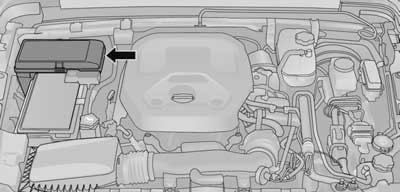
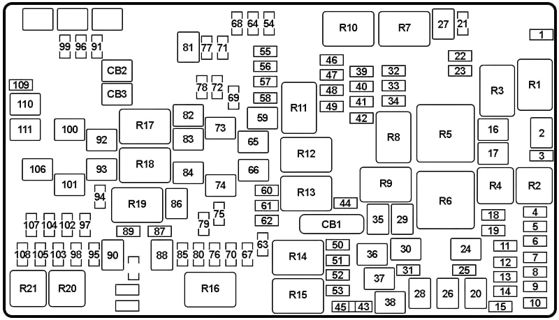
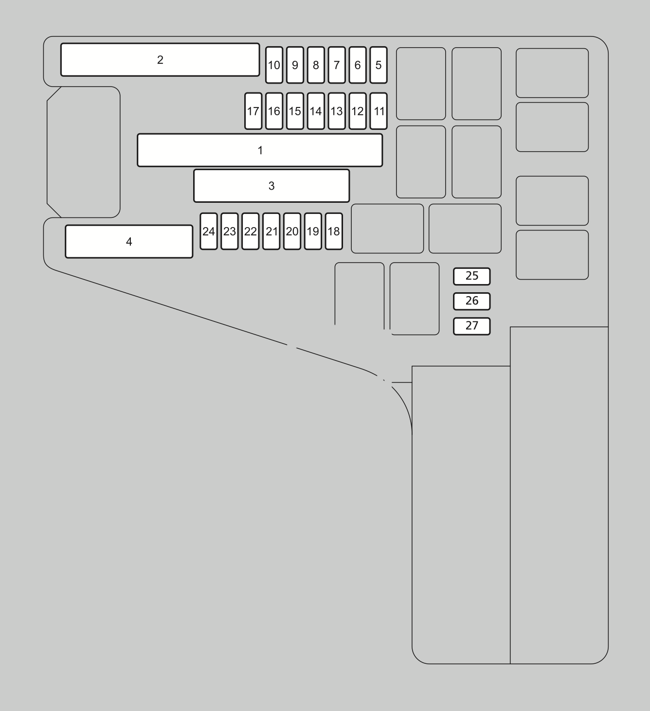
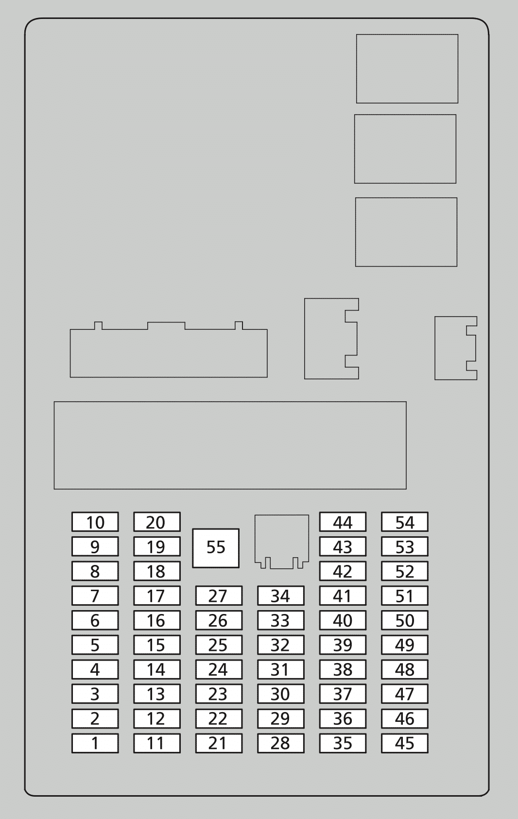
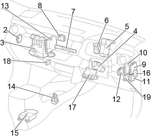
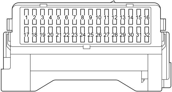
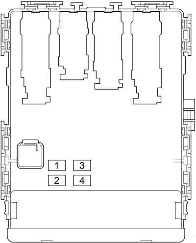
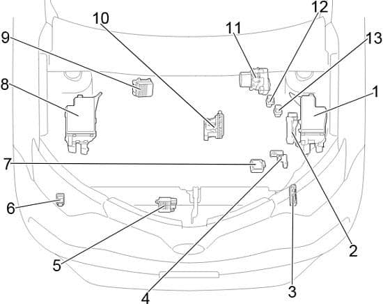
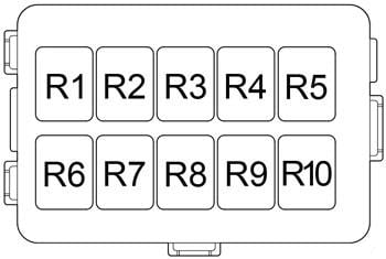
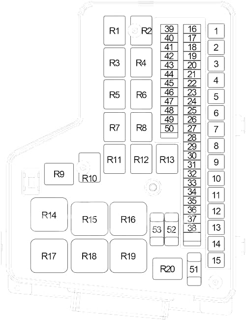
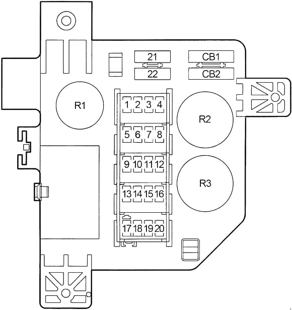
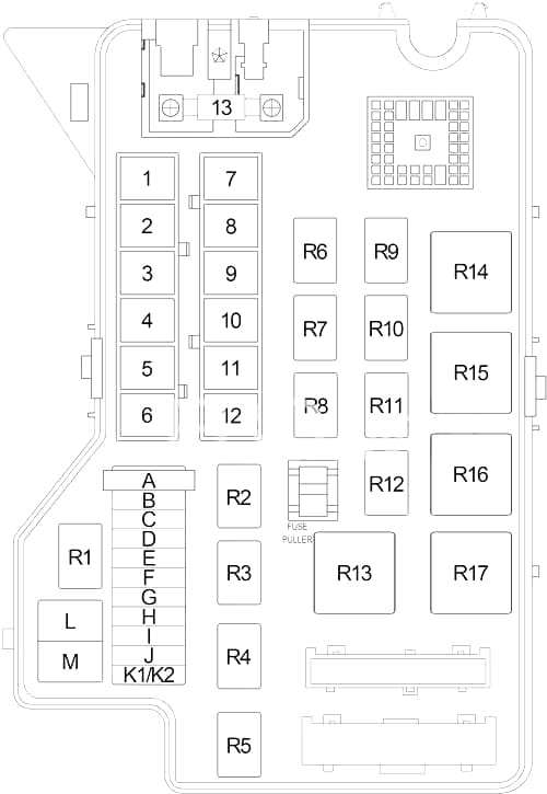
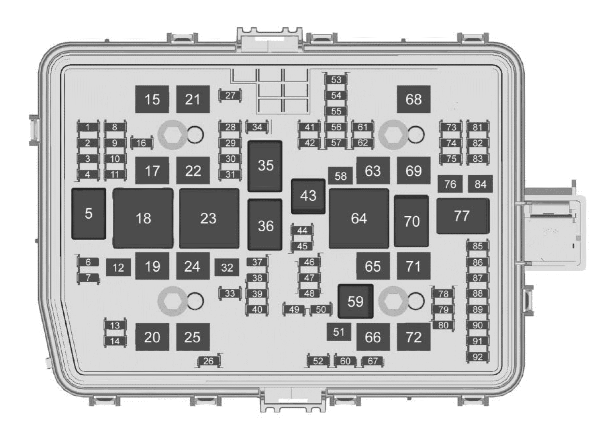
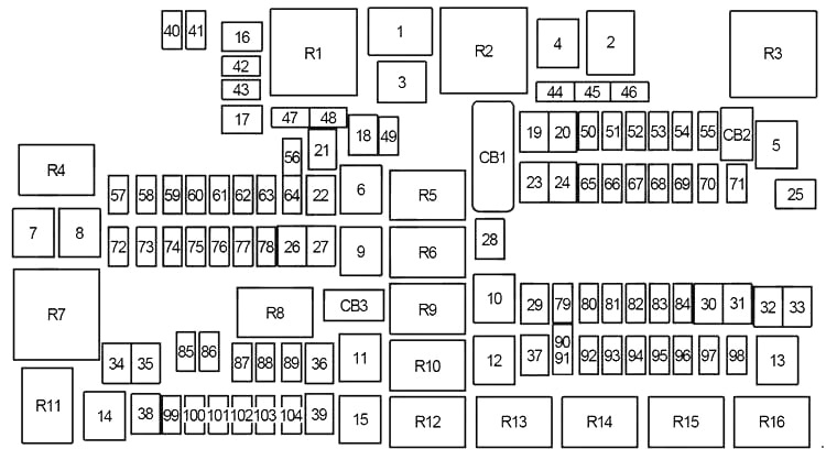
Engine compartment fuse box (power distribution center)
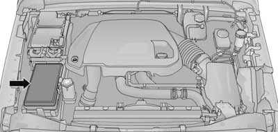
The Power Distribution Center is located in the engine compartment near the battery.
| No. | A | Description |
|---|---|---|
| 1 | – | – |
| 2 | – | – |
| 3 | 60 | Radiator Fan |
| 4 | – | – |
| 5 | 40 | Compressor for Air Suspension |
| 6 | 40 | Anti-lock Brakes/Electronic Stability Control (Pump) |
| 7 | 30 | ’16-’19: Starter Solenoid |
| 40 | ’14-’15: Starter Solenoid | |
| 8 | 40 | Diesel (’14-’15): Emission sensors |
| 9 | 30 | Diesel: Fuel Heater, Brake Vacuum Pump (’16-’19) |
| 30 | Gasoline (’16-’19): Brake Vacuum Pump | |
| 10 | 40 | Body Control Module (BCM) (Exterior Lighting No.2) |
| 11 | 30 | Trailer Tow Electric Brake |
| 12 | 40 | Body Control Module (BCM) (Power Locks) |
| 13 | 40 | Blower Motor Front |
| 14 | 40 | Body Control Module (BCM) (Exterior Lighting No.1) |
| 15 | 40 | ’18-’19: LTR (Low Temperature Radiator) Engine Cooling Pump |
| 16 | – | – |
| 17 | 30 | Headlamp Washer |
| 18 | – | – |
| 19 | 20 | ’16-’19: Headrest Solenoid |
| 20 | 30 | Passenger Door Module |
| 21 | – | – |
| 22 | 20 | Engine Control Module |
| 23 | 30 | Body Control Module (BCM) (Interior Lights No.1) |
| 24 | 30 | Driver Door Module |
| 25 | 30 | Front Wipers |
| 26 | 30 | Anti-lock Brakes/Stability Control Module (Valves) |
| 27 | – | – |
| 28 | 20 | Trailer Tow Backup Lights |
| 29 | 20 | Trailer Tow Parking Lights |
| 30 | 30 | Trailer Tow Receptacle, Trailer Tow (Separate E-Brake), Trailer Tow (BUX) |
| 31 | – | – |
| 32 | 30 | Drive Train Control Module |
| 33 | – | – |
| 34 | 30 | Electronic Limited Slip Differential Module |
| 35 | 30 | Sunroof, Sunroof Shade Motor |
| 36 | 30 | Rear Window Defroster |
| 37 | 25 | ’15-’19: Rear Blower Motor |
| 30 | ’14: Rear Blower Motor | |
| 38 | 30 | Power Inverter 115V AC |
| 39 | 30 | Power Liftgate |
| 40 | 10 | Daytime Running Lights, Headlamp Leveling |
| 41 | – | – |
| 42 | 20 | Horn |
| 43 | – | – |
| 44 | 10 | Diagnostic Connector |
| 45 | 5 | ’18-’19: Cyber Security Gateway |
| 46 | 10 | ’14-’15: Tire Pressure Monitor |
| 47 | – | – |
| 48 | – | – |
| 49 | 10 | Integrated Central Stack, Climate Control |
| 50 | 20 | Air Suspension Module, Electronic Limited Slip Differentials |
| 51 | 15 | ’15-’19: Keyless Ignition Node Module, Radio Frequency Hub Module, Steering Column Lock |
| 10 | ’14: Keyless Ignition Node Module, Radio Frequency Hub Module, Steering Column Lock | |
| 52 | 5 | ’14-: Intelligent Battery Sensor |
| 53 | 20 | Trailer Tow – Left Turn/Stop Lights |
| 54 | – | – |
| 55 | – | – |
| 56 | 15 | Diesel: Additional Content |
| 57 | 20 | ’16-’19: NOX Sensor |
| 15 | ’14: Transmission Control Module | |
| 15 | ’14-’15: HID Headlamps LH | |
| 58 | 15 | ’16-’19: HID Headlamps LH |
| 59 | 10 | Diesel: Purging Pump |
| 60 | 15 | Transmission Control Module |
| 61 | 10 | Diesel (’15-’19): Transmission Control Module, PM Sensor |
| 62 | 10 | Air Conditioning Clutch |
| 63 | 20 | Gasoline: Ignition Coils, Short Runner Valve Actuator |
| 20 | Diesel: Urea Heater | |
| 64 | 25 | Fuel Injectors, Powertrain Control Module (PCM) |
| 65 | – | – |
| 66 | 10 | Sunroof Motor, Sunroof Shade, Passenger Window Switches, Rain Sensor, Inside Rearview Mirror, Charging USB Port, Dedicated Short Range Communications (DSRC), DTV |
| 67 | 15 | CD/DVD/Bluetooth Hands-free Module, Left/Right Seatback Video Screen Module, UCI Port, USB Charging Port |
| 68 | 20 | Rear Wiper Motor |
| 69 | 15 | ’15-’19: Spotlight Feed |
| 70 | 20 | Fuel Pump Motor |
| 71 | 30 | Audio Amplifier, ANCM |
| 72 | 10 | ’16-’19: Powertrain Control Module (PCM) |
| 73 | 15 | HID Headlamp RH |
| 74 | 20 | ’14-’15: Brake Vacuum Pump |
| 75 | 10 | ’16-’19: Dual Batt Control |
| 76 | 10 | Anti-lock Brakes/Electronic Stability Control |
| 77 | 10 | Drivetrain Control Module, Electronic Limited Slip Differential Module |
| 78 | 10 | Engine Control Module, Electric Power Steering |
| 79 | – | – |
| 80 | 10 | Universal Garage Door Opener, Compass, Anti-Intrusion Module |
| 81 | 20 | Trailer Tow Right Turn/Stop Lights |
| 82 | 10 | Steering Column Control Module, Cruise Control, DTV |
| 83 | 10 | Fuel Door Switch |
| 84 | 15 | Switch Bank, Instrument Cluster |
| 85 | 10 | Airbag Module |
| 86 | 10 | Airbag Module |
| 87 | 10 | Air Suspension Control Module, Trailer Tow Module, Steering Column Control Module |
| 88 | 15 | Instrument Panel Cluster, Security Gateway (SGW), Integrated Trailer Brake Module (ITBM) |
| 89 | – | – |
| 90 | 20 | Power Outlet (Rear Seats) |
| 91 | ||
| 92 | 10 | Rear Console Lamp |
| 93 | 20 | Cigar Lighter |
| 94 | 10 | Shifter, Transfer Case Module |
| 95 | 10 | Rear Camera, Park ASsist Module, License Lamp, Rear Blind Spot Sensors |
| 96 | 10 | Rear Seat Heater Switch, Flashlamp Charger |
| 97 | 20 | ’15-’19: Rear Heated Seats, Heated Steering Wheel |
| 25 | ’14: Rear Heated Seats, Heated Steering Wheel | |
| 98 | 20 | ’15-’19: Front Heated Seats, Ventilated Seats |
| 25 | ’14: Front Heated Seats, Ventilated Seats | |
| 99 | 10 | Climate Control, Driver Assistance Systems Module, Dedicated Short Range Communications (DSRC), Adaptive Cruise Control Module, HALF |
| 100 | 10 | Active Damping Control Module |
| 101 | 15 | Electrochromatic Mirror, Smart High Beams, In Car Temperature Sensor, Humidity Sensor |
| 102 | – | – |
| 103 | 10 | Cabin Heater (Diesel), Rear HVAC |
| 104 | 20 | Power Outlets (Instrument Panel, Center Console, Rear Cargo) |
| Circuit Breaker | ||
| CB1 | 25 | Power Window, Power Door Lock |
| CB2 | 25 | Driver Power Seat, Memory Seat Module |
| CB3 | 25 | Passenger Power Seat |
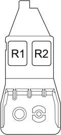
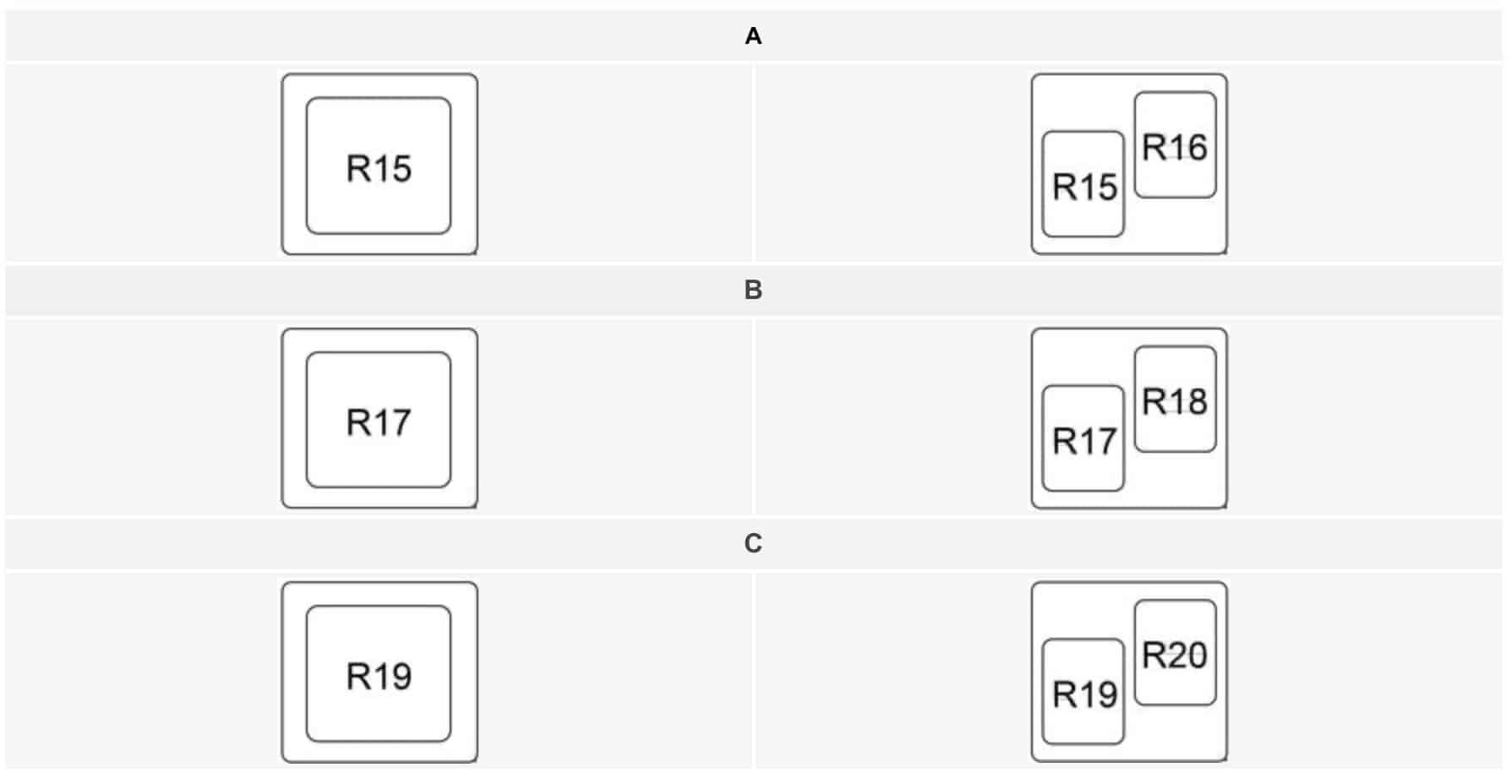
| Relay | ||
| R1 | Radiator Fan (Low Speed) | |
| R2 | Radiator Fan (High Speed) | |
| R3 | Air Suspension | |
| R4 | Selective Catalytic Reduction (SCR) | |
| R5 | Auto Shut Down (Powertrain Control Module) |
|
| R6 | Ignition (Run/Accessory No.1) | |
| R7 | Starter | |
| R8 | Ignition (Run/Start) | |
| R9 | Fuel Heater (No.1) | |
| Air Pump (No.2) | ||
| R10 | EBL | |
| R11 | – | |
| R12 | Ignition (Run/Only No.2) | |
| R13 | Frame Heater | |
| R14 | Ignition (Run/Accessory No.2) | |
| R15 | Ignition (Run/Only No.1) | |
| R16 | Blower Motor | |
WARNING: Terminal and harness assignments for individual connectors will vary depending on vehicle equipment level, model, and market.