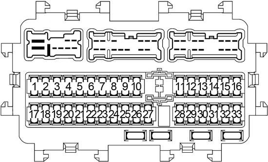
Chrysler Horizon (1982 – 1984) – fuse box diagram

Chrysler Horizon (1982 – 1984) – fuse box diagram

Year of production: 1982, 1983, 1984

Fuse box

Chrysler Horizon - fuse box diagram
Chrysler Horizon – fuse box diagram

A
Protected Component
1 20 Hazard flashers
2 3 Speed control on all, Heated rear window relay (except Rampage)
3 20 Air conditioning radiator fan motor
4 20 Heater blower motor
30 Air conditioning blower motor
5  –
6 20 Dome, map, glove box, cargo and stop lights. Ignition switch time delay relay, key in buzzer, clock, cigar lighter and anti-dieseling relay
7 20 Horn, horn relay, parking lights, side markers, license and tail lights
8  –
9  –
10  –
11 5 Seat belt and brake warning, temperature, oil and fuel lights, voltage limiter and anti-dieseling relay coi
12  –
13 3 Instrument lights, air conditioning/heater control light, heated rear window control light, rear wiper/washer or hatch release control light, ash tray light, radio light and console gear selector light
14 6 Circuit breaker:
4-Door: Rear wiper/washer
   2-Door: Hatch release solenoid
15 5 Radio
16 20 Back-up and turn signal lights, air conditioning clutch, tachometer and heated rear window relay, idle stop solenoid and radiator fan relay coil

WARNING: Terminal and harness assignments for individual connectors will vary depending on vehicle equipment level, model, and market.

Dodge Rampage (1982 – 1984) – fuse box diagram

Dodge Rampage (1982 – 1984) – fuse box diagram

Year of production: 1982, 1983, 1984

Fuse box

Dodge Rampage - fuse box diagram
Dodge Rampage – fuse box diagram

A
Protected Component
1 20 Hazard flashers
2 3 Speed control on all, Heated rear window relay (except Rampage)
3 20 Air conditioning radiator fan motor
4 20 Heater blower motor
30 Air conditioning blower motor
5  –
6 20 Dome, map, glove box, cargo and stop lights. Ignition switch time delay relay, key in buzzer, clock, cigar lighter and anti-dieseling relay
7 20 Horn, horn relay, parking lights, side markers, license and tail lights
8  –
9  –
10  –
11 5 Seat belt and brake warning, temperature, oil and fuel lights, voltage limiter and anti-dieseling relay coi
12  –
13 3 Instrument lights, air conditioning/heater control light, heated rear window control light, rear wiper/washer or hatch release control light, ash tray light, radio light and console gear selector light
14 6 Circuit breaker:
4-Door: Rear wiper/washer
   2-Door: Hatch release solenoid
15 5 Radio
16 20 Back-up and turn signal lights, air conditioning clutch, tachometer and heated rear window relay, idle stop solenoid and radiator fan relay coil

WARNING: Terminal and harness assignments for individual connectors will vary depending on vehicle equipment level, model, and market.

Dodge Omni (1982 – 1984) – fuse box diagram

Dodge Omni (1982 – 1984) – fuse box diagram

Year of production: 1982, 1983, 1984

Fuse box

Dodge Omni - fuse box diagram
Dodge Omni – fuse box diagram

A
Protected Component
1 20 Hazard flashers
2 3 Speed control on all, Heated rear window relay (except Rampage)
3 20 Air conditioning radiator fan motor
4 20 Heater blower motor
30 Air conditioning blower motor
5  –
6 20 Dome, map, glove box, cargo and stop lights. Ignition switch time delay relay, key in buzzer, clock, cigar lighter and anti-dieseling relay
7 20 Horn, horn relay, parking lights, side markers, license and tail lights
8  –
9  –
10  –
11 5 Seat belt and brake warning, temperature, oil and fuel lights, voltage limiter and anti-dieseling relay coi
12  –
13 3 Instrument lights, air conditioning/heater control light, heated rear window control light, rear wiper/washer or hatch release control light, ash tray light, radio light and console gear selector light
14 6 Circuit breaker:
4-Door: Rear wiper/washer
   2-Door: Hatch release solenoid
15 5 Radio
16 20 Back-up and turn signal lights, air conditioning clutch, tachometer and heated rear window relay, idle stop solenoid and radiator fan relay coil

WARNING: Terminal and harness assignments for individual connectors will vary depending on vehicle equipment level, model, and market.

Toyota Tacoma (1998 – 2000) – fuse box diagram

Toyota Tacoma (1998 – 2000) – fuse box diagram

Year of production: 1998, 1999, 2000

Engine Compartment Fuse Box

Location

Toyota Tacoma - fuse box diagram -  engine compartment location
Toyota Tacoma – fuse box diagram – engine compartment location
  1. Fuse Box
  2. Cruise Control Actuator with ECU (5VZ-FE) / O/D Cut Relay (2RZ-FE)
  3. ABS Actuator with ECU

Fuse box

Toyota Tacoma - fuse box diagram -  engine compartment box
Toyota Tacoma – fuse box diagram – engine compartment box
No.
Fuse
A
Designation
1 PWR OUTLET 15 Power outlet
2 Not used
3 DRL 7.5 Daytime running light system
4 Not used
5 HEAD (HI RH) 10 Right-hand headlight (high beam), hi-beam indicator light
6 HEAD (HI LH) 10 Left-hand headlight (high beam)
7 HEAD (LO RH) 10 Right-hand headlight (low beam)
HEAD (RH) 10 Right-hand headlight
8 HEAD (LO LH) 10 Left-hand headlight (low beam)
HEAD (LH) 10 Left-hand headlight
9 TAIL 10 Tail lights, licence plate lights
10 PANEL 10 Emergency flashers, heater control system, air conditioning system, gauges and meters, clock, car audio system, overdrive indicator light, glovebox light, cigarette lighter, instrument panel lights, rear differential lock system, Multiport fuel injection system/sequential multiport fuel injection system, electronically controlled automatic transmission system
11 A.C 10 Air conditioning system
12 Not used
13 Not used
14 Not used
15 STOP 15 Stop lights, high-mounted stoplight, cruise control system
16 Not used
17 Not used
18 ALT-S 7.5 Charging system
19 DOME 15 Car audio system, power antenna, interior light, clock, ignition switch light, personal lights, door courtesy lights
20 OBD 10 On-board diagnosis system
21 HORN 15 Emergency flashers, horns
22 EFI 15 Multiport fuel injection system/sequential multiport fuel injection system
EFI 20 Multiport fuel injection system/sequential multiport fuel injection system
23 ABS 60 Anti-lock brake system
24 HEATER 40 ”A.C” fuse
25 ALT 80 ”ABS”, ”AM1”, ”HEATER”, ”A.C”, ”TAIL”, ”PANEL”, ”STOP” and ”ALT-S”, ”PWR OUTLET” fuses
26 AM1 40 Starting system
27 AM2 30 Ignition system
Relay
R1 Dimmer
R2 EFI
R3 Not used
R4 Power outlet
R5
R6 Taillights
R7 Starter
R8 Headlight
R9 Heater

Passenger Compartment Fuse Box

Location

Toyota Tacoma - fuse box diagram -  passenger ompartment location
Toyota Tacoma – fuse box diagram – passenger ompartment location
  1. Back-Up Light Relay
  2. Integration Relay
  3. Power Window Main Relay
  4. Shift Lock Control Relay (Column A/T) / 4WD Control ECU (with Rear Differential Lock ECU)
  5. J/B
  6. Fuse Box
  7. Circuit Opening Relay
  8. J/B
  9. Auto Antenna Control Relay
  10. J/B
  11. Daytime Running Light Relay No.4
  12. Engine Control Module
  13. ADD Control Relay
  14. Cruise Control ECU (Except 5VZ-FE)
  15. A/C Assembly
  16. 4WD ECU (2-4 Selector)
  17. Center Airbag Sensor Assembly
  18. Shift Lock Control Relay (Floor A/T)
  19. Daytime Running Light Relay (Main)

Fuse box

Toyota Tacoma - fuse box diagram -  passenger compartment box
Toyota Tacoma – fuse box diagram – passenger compartment box
No.
Fuse
A
Designation
1 Not used
2 Not used
3 Not used
4 STA 7.5 Clutch start cancel system, starting system, gauges and meters
5 POWER 30 Power windows
6 4WD 20 A.D.D. control system, four-wheel drive control system, rear differential lock system
7 GAUGE 10 Gauges and meters, back-up lights, cruise control system, power antenna, power door lock control system, electronically controlled automatic transmission system, starting system, charging system, air conditioning system
8 TURN 10 Turn signal lights, emergency flashers
9 ECU-IG 15 Cruise control system, anti-lock brake system, automatic transmission shift lock system
10 WIPER 20 Windshield wipers and washer
11 IGN 7.5 Discharge warning light, SRS airbag system, Multiport fuel injection system/sequential multiport fuel injection system
12 RADIO 7.5 Car audio system, power antenna
13 CIG 15 Cigarette lighter, clock, power rear view mirrors, back-up lights, automatic transmission shift lock system
14 ECU-B 15 SRS airbag warning light, daytime running light system, cruise control system
Relay
R1 Integration Relay
Toyota Tacoma - fuse box diagram -  passenger compartment box
Toyota Tacoma – fuse box diagram – passenger compartment box
No.
Relay
R1 Horn
R2 Turn signal flasher

WARNING: Terminal and harness assignments for individual connectors will vary depending on vehicle equipment level, model, and market.

Porshe 914 (1969 – 1976) – fuse box diagram

Porshe 914 (1969 – 1976) – fuse box diagram

Year of production: 1969, 1970, 1971, 1972, 1973, 1974, 1975, 1976

Fuse box

Porsche 914 - fuse box diagram
Porsche 914 – fuse box diagram
No. A Description
1 16 ’69-’72: Retractable Headlight Motors
25 ’73-’76: Retractable Headlight Motors
2 8 Emergency Flashers, Interior Light (possibly turn signals and their indicator lights, parking brake indicator light, speedometer gauge light, fuel gauge light, tach gauge light, temp control light)
3 16 ’69-’72: Fog/Driving Lights, parking lights indicator light, horn
8 ’73-’76: Fog/Driving Lights, parking lights indicator light, horn
4 8 Fresh Air Fan, Reverse Light Switch (possibly tail lights, tach, fuel gauge, oil temp gauge, voltage gauge, alternator idiot light, low fuel idiot light, oil pressure idiot light, clock)
5 16 ’69-’72: Wipers, Cigarette Lighter, Turn Signals, Brake Lights, Backup Light (possibly horn, heater control lights, fresh air fan indicator light, fresh air fan motor)
25 ’73-’76: Wipers, Cigarette Lighter, Turn Signals, Brake Lights, Backup Light (possibly horn, heater control lights, fresh air fan indicator light, fresh air fan motor)
6 8 License Plate Lights, clock light, voltage gauge light, rear trunk light, engine bay light (possibly oil temp light, defrost light)
7 8 Parking Lights – Right (possibly side marker lights, right brake light)
8 8 Parking Lights – Left (possibly side marker lights, left brake light)
9 8 Right Low Beam
10 8 Left Low Beam
11 8 Right High Beam
12 8 Left High Beam, and high beam indicator light

WARNING: Terminal and harness assignments for individual connectors will vary depending on vehicle equipment level, model, and market.

Ford Thunderbird (1983 – 1988) – fuse box diagram

Ford Thunderbird (1983 – 1988) – fuse box diagram

Year of production: 1983, 1984, 1985, 1986, 1987, 1988

Fuse box

Ford Thunderbird - fuse box diagram
Ford Thunderbird – fuse box diagram
No. A Description
1 15 Brake & Hazard Warning Lights, Speed Control Module, Cornering Light Relay
2 6 Circuit Breaker: Windshield Wiper & Washer Pump, Interval Wiper
3  –
4 15 Taillights, License & Parking Lights, Side Marker & Coach Lights, Cluster Illumination Lights, Radio & Clock Illuminator, A/C-Heater Illumination
5 15 Turn Signal & Back-Up Lights, Keyless Entry Illumination, Day/Night Mirror, Turbo Overboost Buzzer
6 20 Heated Back Light Control, Deck Lid Release, Electronic Chime Module, Lights Outage & Clock Display, Cornering & Rear Reading Lights, Tripminder, Illuminated Entry, Anti-Theft Module, Radio & Cluster Illumination
7 15 Foglights (Turbo Only)
8 15 Courtesy & Glove Box Lights, Key Warning Buzzer, Illuminated Entry Module, Remote Electric Mirrors, Electronic Radio & Cluster Memories, Anti-Theft Relay & Clock
9 30 A/C-Heater Blower Motor
10 20 Horn, Cigarette Lighter, Flash-To-Pass Feature, Fuel Filler Door, Speed Control
11 20 Radio, Power Antenna, Sound Amplifier
12 20 Circuit Breaker: Power Seat & Door Locks, Keyless Entry, Fuel Filler Door Lock
13 5 Instrument Cluster, Radio, Climate Control, Instrument Panel Illumination
14 20 Power Windows, Power Moon Roof
15 10 Taillights, Parking Lights, License & Coach Lights
16 4 EATC Memory, Horn, Cigarette Lighter
17 15 Electronic Cluster Tripminder, Fuel Gauge, A/C Clutch, Speed Control Module, Graphic Warning Module
18 10 Warning Indicator Lights, Auto Light System, Electronic

WARNING: Terminal and harness assignments for individual connectors will vary depending on vehicle equipment level, model, and market.

Nissan 240SX (1989 – 1994) – fuse box diagram

Nissan 240SX (1989 – 1994) – fuse box diagram

Year of production: 1989, 1990, 1991, 1992, 1993, 1994

Passenger Compartment

Nissan 240SX - fuse box diagram - passenger compartment - location
Nissan 240SX – fuse box diagram – passenger compartment – location
  1. Fuse Block
  2. Rear Defogger Relay
  3. Buld Check Relay
  4. Ignition Relay
  5. Circuit Breaker
  6. Accessory Relay 1
  7. ECCS Control Unit
  8. ASCD Control Unit
  9. Automatic Transmission Control Unit
  10. Door Lock Timer
  11. Vehicle Speed Sensor
  12. Automatic Seat Belt Control Unit
  13. Kickdown Switch
  14. Turn Signal / Hazard Flasher
  15. ASCD Cancel Switch
  16. Stoplight Switch
  17. Shift Lock Control Unit
  18. Time Control Unit
  19. Headlight Timer
  20. Chime

Passenger Compartment Fuse Box

Nissan 240SX - fuse box diagram - passenger compartment
Nissan 240SX – fuse box diagram – passenger compartment
No.
A
Circuit Protected
1 15 Blower Motor
2 15 Blower Motor
3 10 Heater & Air Conditioner
4 15 Cigarette Lighter
5 20 Front Windshield Wiper & Washer
6 10 Rear Window Wiper & Washer, Door Mirror System
7 10 Head-up Display Control Unit, Time Control Unit, Radio, Audio, Rear Window Defogger Relay, Digital Gauges Illumination, Auto Antenna Timer (’90-’95)
8 10 Turn Signals
9 10 Gauges, Head-Up Display Control Unit, Automatic Seat Belt Control Unit, Auto Antenna Timer (’90-’95), Time Control Unit, Daytime Running Lights (Canada)
10 10 Cruise Control, HICAS Control Unit
11 20 Rear Window Defogger
12 20 Rear Window Defogger
13 10 Interior Lights, Radio, Audio, Clock, Warning Chime, Time Control Unit, A/T Control Unit, Head-Up Display Control Unit, Automatic Seat Belt Control Unit, HICAS Control Unit, Auto Antenna Timer (’90-’95)
14 15 Stoplight, Shift Lock Control Unit, Cruise Control Unit
15 10 Hazard Warning Light
16 5 Headlight Timer, Retractor Relay
17 10 Daytime Light Control Unit (’90-’95)
18 15 Exterior Lights, Illumination, Glove Box Light, Headlight Timer, Time Control Unit
19 10 ECCS Control Unit, Daytime Light Control Unit (’90-’95)
20 10 Back-Up Light, Inhibitor Switch, A/T Control Unit, Shift Lock Control Unit, ABS Control Unit (’90-’95), HICAS Warning Light (If Equipped)

Engine Compartment

Nissan 240SX - fuse box diagram - engine compartment - location
Nissan 240SX – fuse box diagram – engine compartment – location
  1. Fuse Block
  2. Wiper Motor
  3. ASCD Pump
  4. Ignition Coil & Power Transistor
  5. Dropping Resistor
  6. Relay Box
  7. Daytime Light Control Unit
  8. Interlock Relay

Engine Compartment Fuse Box

Nissan 240SX - fuse box diagram - engine compartment
Nissan 240SX – fuse box diagram – engine compartment
A Description components
1 15 Front Foglight
2 10 Horn, Cruise Control
3 20 ’91-’95: Anti-Lock Brake System
4 10 Bulb Check Relay
5 10 Fuel Pump, Air Regulator
6 10 Shift Lock Control Unit, Key Switch
7 15 Right Headlight
8 15 Left Headlight
Nissan 240SX - fuse box diagram - engine compartment
Nissan 240SX – fuse box diagram – engine compartment
Description components
R1 ECCS
R2 Fuel Pump
R3 Headlight Retract (No.4)
R4 Inhibitor

Engine Compartment Relay Box

Nissan 240SX - fuse box diagram - engine compartment relay box
Nissan 240SX – fuse box diagram – engine compartment relay box
Description components
R1 Accessory (No.2)
R2 ASCD Hold
R3 Air Conditioner
R4 Fog Light
R5 Headlight Retract (No.2)
R6 Headlight Retract (No.1)
R7 Headlight Retract (No.3)
R8 Horn

WARNING: Terminal and harness assignments for individual connectors will vary depending on vehicle equipment level, model, and market.

Ford Festiva (1988 – 1993) – fuse box diagram

Ford Festiva (1988 – 1993) – fuse box diagram

Year of production: 1988, 1989, 1990, 1991, 1992, 1993

Passenger Compartment Fuse Box

Ford Festiva - fuse box diagram - passenger compartment
Ford Festiva – fuse box diagram – passenger compartment

A
Protected Component
1  –
2 15 Front Wiper/Washer, Shift-Lock System (ATX (’90-’93)), Engine Control System (’90-’93)
3 15 Rear Wiper/Washer, Daytime Running Light System (Canada)
4  –
5 15 Spare
6 15 Heater & Air Conditioner
7 20 Cooling Fan System, Heater & Air Conditioner
8  –
9 10 Charging System, Emission Control System
10 10 Safety Belt Warning, Turn & Hazard Warning Flasher Lights, Back-Up Lights, Instrument Cluster, Warning Lights, Shift-Lock System (’90-’93)
11 15 Rear Window Defroster
12 30 Climate Control Blower Motor
13 15 Horn, Brakelights, High-Mount Brakelight
14 15 Safety Belt Warning, Turn & Hazard Warning Flasher Lights, Radio (’88-’89), Trunk Light (’88-’89), Ignition Key Reminder Buzzer
15 10 Interior Courtesy Lights, Luggage Compartment Light (’90-’93), Radio (’90-’93)
16 15 License Plate Light, Rear Side Marker Light, Front Parking Lights, Cluster and Tail Lights
17  –
18 15 Audio System, Cigarette Lighter, Remote Control Mirror
19 30 Passive Restraint System (Automatic Seat Belt (’90-’93))

Engine Compartment Fuse Box

Ford Festiva - fuse box diagram - engine compartment
Ford Festiva – fuse box diagram – engine compartment
Fusible Link
A EFE Carburetor Heater (’88-’89), EFI System (’89-’92), EGI-EFI System (’93)
B Back-Up, Interior & Parking Lights, Brakelights, Taillights, Horn, Luggage Compartment Light, Turn Signal & Hazard Flasher Lights, Cluster & Warning Lights, Radio, Cigarette Lighter, Charging & Emission Control Systems, Wiper/Washer Systems, A/C-Heater System, Cooling Fan System, Rear Window Defroster, Ignition & Starting Systems, Shift Lock System, Remote Control Mirror, Ignition Key Reminder, Passive Restraint System (’90-’93)
C Headlights, Daytime Running Lights, Starting & Charging System

In-Line Fuse

A Description components
15 Condenser Fan Motor (A/T Models Only (’90-’93))
10 A/C System (located on left side of heater case (’90-’93))

WARNING: Terminal and harness assignments for individual connectors will vary depending on vehicle equipment level, model, and market.

Suzuki Swift (1989 – 1994) – fuse box diagram

Suzuki Swift (1989 – 1994) – fuse box diagram

Year of production: 1989, 1990, 1991, 1992, 1993, 1994

Passenger Compartment Fuse Box

Suzuki Swift - fuse box diagram - passenger compartment
Suzuki Swift – fuse box diagram – passenger compartment
A Description components
1 10 Left Side Headlight & High Beam Indicator
2 10 Right Side Headlight
3 15 Dome Light, License Plate Light, Front & Rear Marker Light, Instrument Panel Illumination
4 15 Front Foglight
5 15 Hazard Warning Circuit & Horn
6 20 Ignition System & Gauges, Warning Lights
7 20 Heater Fan Motor, A/C Circuit
8 15 Stoplights
9 15 Cigarette Lighter & Radio
10 10 Back-Up Light
11 15 Rear Defogger
12 15 Front & Rear Wiper/Washer
Relay
13 Switch
14 Turn Signal

Engine Compartment Fuse Box

Suzuki Swift - fuse box diagram - engine compartment
Suzuki Swift – fuse box diagram – engine compartment
A Description components
A 60 Main
B 40 Primary
C 30 Primary
D 30 A/C
E 15 Electronic Fuel Injection
F 15 A/C

WARNING: Terminal and harness assignments for individual connectors will vary depending on vehicle equipment level, model, and market.

Pontiac Lemans (1979) – fuse box diagram

Pontiac Lemans (1979) – fuse box diagram

Year of production: 1979

Fuse box

Pontiac Lemans - fuse box diagram
Pontiac Lemans – fuse box diagram
No.
A
Circuit Protected
1  –
2 20 Clock power, courtesy lights, deck lid release, glove box light, pulse wiper, power antenna, key reminder buzzer and cigar lighter
3 20 Tail, park, side marker and license lights; digital AM/FM clock receiver
4 20 Stop, hazard, dome and trunk lights
5 4 Instrument panel, ash tray, clock, shift indicator, radio, cigar, heater or A/C control, and tachometer lights
6 25 Heater and A/C blower motor, window control relay, tachometer and cruise control
7 20 Backup lights, turn signals and electric choke feed
8 10 Oil pressure, voltage, temperature and fuel gauges; low brake, park brake and seat belt warning telltale; seat belt warning buzzer and timer (actuating coil) and heated rear glass (actuating coil feed)
9 10 Radio and tape player; digital AM/FM clock receiver, CB radio, power antenna and cruise control
10 25 Windshield wiper and washer; pulse wiper

WARNING: Terminal and harness assignments for individual connectors will vary depending on vehicle equipment level, model, and market.