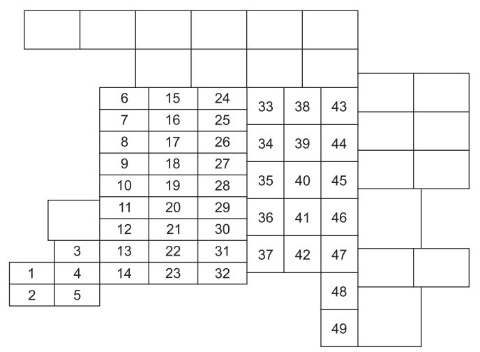
No.
|
A
|
Circuit Protected |
| 1 |
10 |
2003-2004: Run/Accessory – Instrument cluster, Front wiper motor, Rear wiper motor, Tire Pressure Monitor System (TPMS) module |
| 7.5 |
2005-2006: Run/Accessory – Instrument cluster, Front wiper motor, Rear wiper motor |
| 2 |
20 |
Brake On/Off (stoplamp) switch, Turn signal/Hazard flasher, AdvanceTrac®stoplamps relay (2003-2004), Stoplamps, Center High-Mounted Stoplamp (CHMSL), Turn signal lamps |
| 3 |
7.5 |
Power mirror switch, Memory module (logic power), Driver seat switch (memory) |
| 4 |
15 |
Rear seat audio controls, Navigation module, DVD player |
| 5 |
7.5 |
Brake On/Off (stoplamp) switch, Powertrain Control Module (PCM) (keep alive power), EATC control head, Body Security Module (BSM) (keep alive power), Speed control deactivation switch, Speed control servo (2003-2004), SecuriLock LED, 3rd row seat relay coils, Power liftgate module, Clock, Brake Shift Interlock (BSI) solenoid |
| 6 |
15 |
Headlamp switch (parklamps and switch backlighting feed), Parklamps, License lamps, Foglamp relay coil, Trailer tow electric brake controller (illumination), BSM (autolamp parklamps), Floor console gear selector lighting, Switch backlighting module (2003-2004), Foglamp indicator |
| 7 |
7.5 |
2003-2004: Radio (Start signal) |
| 5 |
2005-2006: Radio (Start signal) |
| 8 |
10 |
Rear window defroster switch, Heated outside mirrors, Rear window defroster indicator (climate control head) |
| 9 |
15 |
2004: Fuel pump relay, Fuel pump shut-off switch, Fuel pump motor
2005-2006: Transmission control module |
| 10 |
20 |
Trailer tow back-up lamps relay, Trailer tow 7-wire connector (back-up lamps), Trailer tow parklamps relay, Trailer tow 7-and 4-wire connectors (parklamps) |
| 11 |
10 |
A/C compressor clutch relay, A/C compressor clutch solenoid, Air suspension compressor relay (2003-2004), 4×4 Integrated Wheel Ends (IWE) solenoid |
| 12 |
10 |
2003-2004: Speed control relay, Speed control servo |
| 15 |
2005-2006: Fuel pump relay, Fuel pump shut-off switch, Fuel pump driver module, Fuel pump motor |
| 13 |
10 |
Rear window defroster relay coil, A/C refrigerant containment switch, A/C compressor thermistor (2003-2004), A/C de-icing switch (2005-2006), A/C low pressure switch (2005-2006), DEATC/DATC control head, DEATC/DATC solenoids, DEATC/DATC blower controller, Trailer tow battery charge relay coil |
| 14 |
10 |
Daytime Running Lamps (DRL) ignition relay coil, Digital Transmission Range Sensor (DTRS back-up lamps (2003-2004)), Trailer tow back-up lamps relay coil, Elctrochromatic mirror, Back-up lamps relay (2005-2006), Back-up lamps (2005-2006) |
| 15 |
5 |
AdvanceTrac® switch, Instrument cluster (Run/Start feed) |
| 16 |
10 |
ABS/AdvanceTrac® module (Run/Start feed) |
| 17 |
15 |
Foglamps |
| 18 |
10 |
Auxiliary A/C temperature blend door actuator, Auxiliary A/C front auxiliary control, Park brake release relay coils, Turn signal flasher, Electrochromatic mirror, Auxiliary mode motor, Climate controlled seat modules (2003-2004) |
| 19 |
10 |
Restraints Control Module (RCM) |
| 20 |
30 |
2003-2004: 4×4 module, Air suspension module (air spring solenoids and height sensors)
2005-2006: BSM (door locks, liftgate glass release relay), Liftgate glass release motor, Left front window motor, Door/Liftgate lock motors |
| 21 |
15 |
Instrument cluster (B+), Interior (courtesy) lamps, TPMS module (2003-2004), Park brake release relays, Park brake release motor, Puddle lamps (outside mirrors) |
| 22 |
10 |
Moonroof switch illumination, Flip window switch, Flip window relays, Flip window motors, Electronic Hidden Antenna Module (EHAM) antenna amplifier (navigation radio), Radio (delayed accessory feed), Left front window motor, Navigation module |
| 23 |
10 |
RH low beam |
| 24 |
15 |
Interior demand lamps (front map/dome lamps, glove compartment lamp, cargo lamp, roof rail lamps, vanity mirror lamps), Battery saver relay coil, Battery saver relay power, Heated Positive Crankcase Ventilation (PCV) valve (2005-2006), Heated PCV valve relay (2005-2006) |
| 25 |
10 |
LH low beam |
| 26 |
20 |
Horn relay, Horns |
| 27 |
5 |
Brake Shift Interlock solenoid, Overdrive cancel switch (2003-2004), Reverse park aid system module, Air suspension module (Run/Start), Compass module |
| 28 |
5 |
PCM relay coil, Speed control relay coil (2003-2004), SecuriLock transceiver, Heated PCV valve relay coil (2005-2006) |
| 29 |
30 |
Trailer tow electric brake controller, Trailer tow 7-wire connector (electric brake) |
| 30 |
30 |
2003-2004: BSM (door locks, liftgate glass release relay), Liftgate glass release motor, Left front window motor, Door/Liftgate lock motors |
| 25 |
2005-2006: PCM (4×4 transfer case clutch), Air suspension module (air spring solenoids and height sensors) |
| 31 |
25 |
2003: Radio (B+), Subwoofer, Navigation radio audio amplifier |
| 20 |
2004-2006: Radio (B+), Subwoofer, Navigation radio audio amplifier |
| 32 |
15 |
2003-2004: Catalyst Monitor Sensors (CMS), Transmission solenoids
2005-2006: Catalyst Monitor Sensors (CMS), 6–speed transmission (ignition sense), HEGO sensors, Canister vent solenoid, Vapor Management valve (VMV) solenoid, A/C compressor clutch relay coil, CMCV, VCT actuators |
| 33 |
20 |
2003-2004: HEGO sensors, EGR vacuum regulator (EVR) solenoid, Intake Manifold Tuning valve (IMTV) solenoid, Canister vent solenoid, Vapor Management valve (VMV) solenoid, A/C compressor clutch relay coil |
| 34 |
20 |
2003: PCM, Idle Air Control (IAC) solenoid, Mass Air Flow (MAF) sensor, Fuel injectors, Fuel pump relay, Fuel pump shut-off switch, Fuel pump motor |
| 15 |
2004: PCM, Idle Air Control (IAC) solenoid, Mass Air Flow (MAF) sensor, Fuel injectors
2005-2006: PCM, Mass Air Flow (MAF) sensor, Fuel injectors |
| 35 |
20 |
High beam headlamps, Instrument cluster high beam indicator |
| 36 |
10 |
Trailer tow right turn/stop lamps |
| 37 |
20 |
Cargo area power point |
| 38 |
25 |
Rear wiper motor, Washer pump (rear window wash) |
| 39 |
20 |
Console power points |
| 40 |
20 |
DRL relays, DRL foglamps, DRL headlamp relay coil, Headlamp switch (headlamps), Multifunction switch (flash-to-pass), BSM (autolamp headlamps relay), High beam relay coil, Fuse 25 (LH low beam), Fuse 23 (RH low beam) |
| 41 |
20 |
Cigar lighter, OBD II diagnostic connector |
| 42 |
10 |
Trailer tow left turn/stop lamps |
| 101 |
30 |
Starter motor relay, Starter motor solenoid |
| 102 |
30 |
Ignition switch power |
| 103 |
30 |
ABS/AdvanceTrac® module (pump motor) |
| 104 |
30 |
LH 3rd row seat relay, LH 3rd row seat switch, LH 3rd row seat motor |
| 105 |
40 |
2003: Power liftgate module, Power liftgate motors, Power running boards control |
| 30 |
2004-2006: Power liftgate module, Power liftgate motors, Power running boards control |
| 106 |
30 |
Trailer tow battery charge relay, Trailer tow 7-wire connector (battery charge) |
| 107 |
30 |
Auxiliary A/C blower relay, Auxiliary A/C blower motor |
| 108 |
30 |
Passenger seat motor switch, Passenger seat lumbar switch and motor |
| 109 |
30 |
Driver seat lumbar switch and motor, Memory module, Power memory mirrors, Adjustable pedals switch and motor |
| 110 |
30 |
Power running boards |
| 111 |
50 |
Air suspension compressor relay, Air suspension compressor |
| 112 |
30 |
ABS/AdvanceTrac® module (valves) |
| 113 |
30 |
Front wiper motor, Washer pump (windshield wash) |
| 114 |
40 |
Rear window defroster relay, Rear window defroster grid, Heated mirrors (Fuse 8) |
| 115 |
30 |
4×4 module (2003-2004), Transfer case shift motor, 4×4 relays (2005-2006) |
| 116 |
40 |
Front blower motor relay, Front blower motor |
| 117 |
30 |
RH 3rd row seat relay, RH 3rd row seat switch, RH 3rd row seat motor |
| 118 |
30 |
Driver and passenger climate control seat module |
| 401 |
30 |
Circuit Breaker: Power windows (circuit breaker), Main window switch, Window motors, Window switches, Moonroof module |
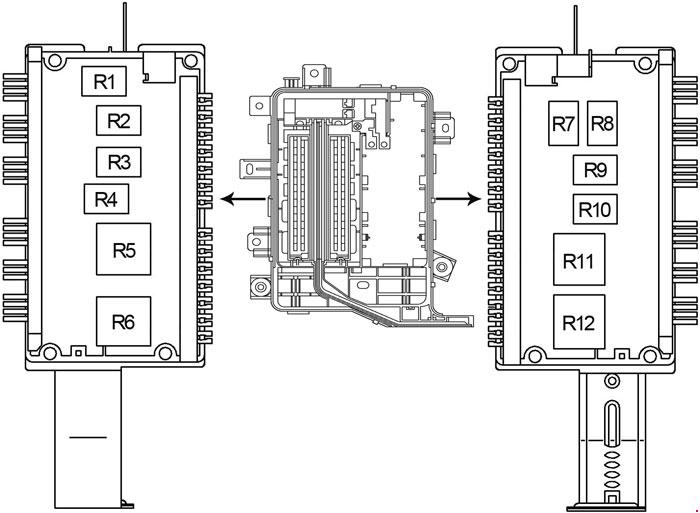
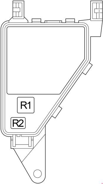
| Relay |
| R01 |
Starter |
| R02 |
Delayed accessory (Fuse 22, CB 401, Power windows, Moonroof, Flip windows, Radio, DVD (2003), Navigation module, Navigation antenna amplifier) |
| R03 |
Hi-beam |
| R04 |
Rear window defrost (Rear window defroster, Heated outside mirrors) |
| R05 |
Trailer tow battery charge |
| R06 |
Front blower |
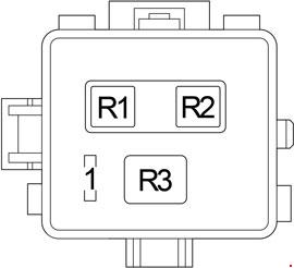
| R201 |
Trailer tow park lamp |
| R202 |
Foglamp |
| R203 |
2003-2004: PCM (Fuse 32, Fuse 33, Fuse 34, Fuel pump relay, Fuel pump, PCM solenoids and sensors)
2005-2006: PCM (Fuse 32, Fuse 34, PCM solenoids and sensors) |
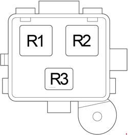
| R301 |
Trailer tow back-up lamp |
| R302 |
2003-2004: Speed control
2005-2006: Heated PCV valve |
| R303 |
Fuel pump |
| R304 |
Battery saver relay (Roof rail lamps, Vanity mirror lamps, Map/Dome lamp, Glove box lamp, Cargo area lamp, Outside mirror puddle lamps, Instrument cluster (interior lamps)) |
| R305 |
Horn |