AMC Matador (1971 – 1978) – fuse and relay box diagram
Year of production: 1971, 1972, 1973, 1974, 1975, 1976, 1977, 1978
This article covers the second-generation AMC Matador, produced from 1971 to 1978. It includes fuse box diagrams for the 1971, 1972, 1973, 1974, 1975, 1976, 1977 and 1978 models, provides details on the location of the fuse panels inside the vehicle, and explains the function and layout of each fuse.
Fuse box diagram
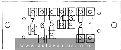
Assignment of the fuses in the fuse box
| No. |
A |
Protected Component |
| 1 | 20 | Turn signal, back-up lights, radio, windshield washer |
| 2 | 20 | Blower motor, air conditioner clutch |
| 3 | 4 | Interlock module circuit, headlight warning buzzer, oil light indicator, park brake, brake failure circuit |
| 4 | 4 | Panel illumination lights |
| 5 | 14 | Interlock module circuit, windshield wiper, park, tail, license and side marker lights |
| 6 | 20 | Stop light and hazard warning flasher |
| 7 | 9 | Dome, courtesy, glove box, trunk and cargo lights, clock |
Circuit Breaker:
|
||
WARNING: Terminal and harness assignments for individual connectors will vary depending on vehicle equipment level, model, and market.