Audi S4 (2014 – 2016) – fuse box diagram
Year of production: 2014, 2015, 2016
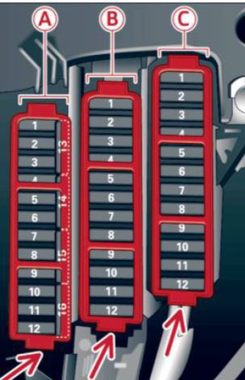
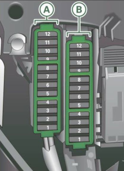
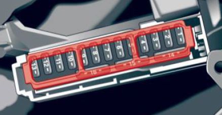
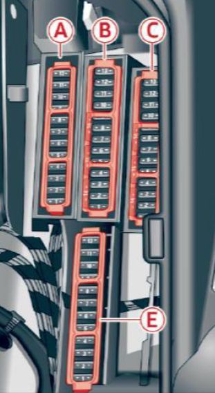
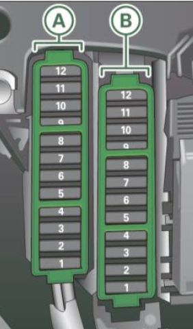
Instrument panel (driver’s side)
 Audi S4 – fuse box diagram – left cocpit
Fuse panel A (black)
| Number |
Electric equipment |
Ampere rattings [A] |
| 1 |
Dynamic steering |
5 |
| 2 |
Electronic Stabilization Control (module) |
5 |
| 3 |
A/C system pressure sensor, electromechanical parking brake, Homelink, automatic dimming interior rear view mirror, air quality/outside air sensor, Electronic Stabilization Control (button) |
5 |
| 4 |
— |
— |
| 5 |
Sound actuator |
5 |
| 6 |
Headlight range control/head light (cornering light) |
5/7,5 |
| 7 |
Headlight (cornering light) |
7,5 |
| 8 |
Control modules (electromechanical parking brake, shock absorber, quattro sport), DCDC converter |
5 |
| 9 |
Adaptive cruise control |
5 |
| 10 |
Shift gate/clutch sensor |
5 |
| 11 |
Side assist |
5 |
| 12 |
Headlight range control, parking system |
5 |
| 13 |
Airbag |
5 |
| 14 |
Rear wiper (allroad) |
15 |
| 15 |
Auxiliary fuse (instrument panel) |
10 |
| 16 |
Auxiliary fuse terminal 15 (engine area) |
40 |
Fuse panel B (brown)
| Number |
Electric equipment |
Ampere rattings [A] |
| 1 |
— |
— |
| 2 |
Brake light sensor |
5 |
| 3 |
Fuel pump |
25 |
| 4 |
Clutch sensor |
5 |
| 5 |
Left seat heating with/without seat ventilation |
15/30 |
| 6 |
Electronic Stabilization Control (electric) |
5 |
| 7 |
Horn |
15 |
| 8 |
Front left door (window regulator, central locking, mirror, switch, lighting) |
30 |
| 9 |
Windshield wiper motor |
30 |
| 10 |
Electronic Stabilization Control (valves) |
25 |
| 11 |
Two-door models: rear left window regulator, Four-door models: rear left door (window regulator, central locking, switch, lighting) |
30 |
| 12 |
Rain and light sensor |
5 |
Fuse panel C (red)
| Number |
Electric equipment |
Ampere rattings [A] |
| 1 |
— |
— |
| 2 |
— |
— |
| 3 |
Lumbar support |
10 |
| 4 |
Dynamic steering |
35 |
| 5 |
Interior lighting (Cabriolet) |
5 |
| 6 |
Windshield washer system, headlight washer system |
35 |
| 7 |
Vehicle electrical system control module 1 |
20 |
| 8 |
Vehicle electrical system control module 1 |
30 |
| 9 |
Left rear window regulator motor (Cabriolet)/sunroof |
7,5/20 |
| 10 |
Vehicle electrical system control module 1 |
30 |
| 11 |
Right rear window regulator (Cabriolet)/sun shade motor |
7,5/20 |
| 12 |
Anti-theft alarm warning system |
5 |
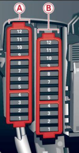
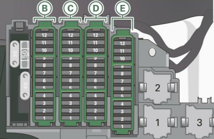
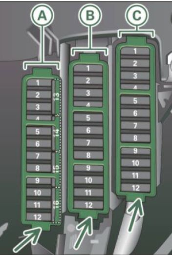
Instrument panel (right)
 Audi S4 – fuse box diagram – right cocpit
Fuse carrier A (black)
| Number |
Electric equipment |
Ampere rattings [A] |
| 1 |
— |
— |
| 2 |
— |
— |
| 3 |
— |
— |
| 4 |
— |
— |
| 5 |
Steering column switch module |
5 |
| 6 |
— |
— |
| 7 |
Terminal 15 diagnostic connector |
5 |
| 8 |
Gateway (Databus diagnostic interface) |
5 |
| 9 |
Supplementary heater |
5 |
| 10 |
— |
— |
| 11 |
— |
— |
| 12 |
— |
— |
Fuse panel B (brown)
| Number |
Electric equipment |
Ampere rattings [A] |
| 1 |
CD-/DVD player |
5 |
| 2 |
Wi-Fi |
5 |
| 3 |
MMI/Radio |
5/20 |
| 4 |
Instrument cluster |
5 |
| 5 |
Gateway (instrument cluster control module) |
5 |
| 6 |
Ignition lock |
5 |
| 7 |
Light switch |
5 |
| 8 |
Climate control system blower |
40 |
| 9 |
Steering column lock |
5 |
| 10 |
Climate control system |
10 |
| 11 |
Terminal 30 diagnostic connector |
10 |
| 12 |
Steering column switch module |
5 |
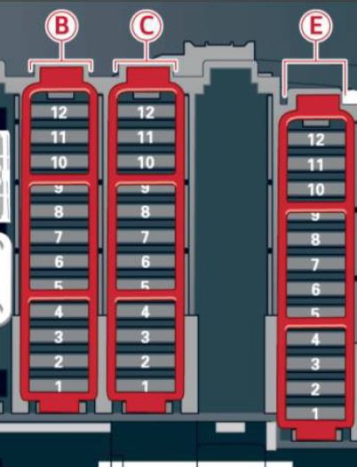
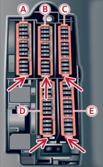
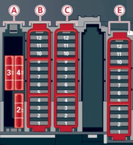
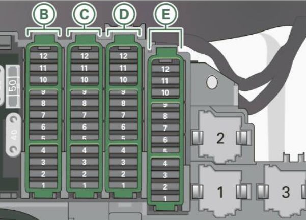
Luggage compartment
 Audi S4 – fuse box diagram – luggage compartment
Fuse panel A (black)
| Number |
Electric equipment |
Ampere rattings [A] |
| 1 |
— |
30 |
| 2 |
Rear window heater (Cabriolet) |
30 |
| 3 |
Power top latch (Cabriolet) |
30 |
| 4 |
Power top hydraulics (Cabriolet) |
50 |
Fuse panel B (black)
| Number |
Electric equipment |
Ampere rattings [A] |
| 1 |
Luggage compartment lid control module (all road) / Power top control module (Cabriolet) |
30/10 |
| 2 |
Retractable rear spoiler (RS 5 Coupe) |
10 |
| 3 |
— |
— |
| 4 |
— |
— |
| 5 |
Electromechanical parking brake |
5 |
| 6 |
Electronic damping control |
15 |
| 7 |
Electromechanical parking brake |
30 |
| 8 |
Rear exterior lighting |
30 |
| 9 |
Quattro Sport |
35 |
| 10 |
Rear exterior lighting |
30 |
| 11 |
Central locking |
20 |
| 12 |
Terminal 30 |
5 |
Fuse panel C (brown)
| Number |
Electric equipment |
Ampere rattings [A] |
| 1 |
Luggage compartment lid control module (allroad) |
30 |
| 2 |
12-volt socket, cigarette lighter |
20 |
| 3 |
DCDC converter path 1 |
40 |
| 4 |
DCDC converter path 2, DSP amplifier, radio |
40 |
| 5 |
Right upper cabin heating (Cabriolet) |
30 |
| 6 |
— |
— |
| 7 |
Electromechanical parking brake |
30 |
| 8 |
— |
— |
| 9 |
Right front door (window regulator, central locking, mirror, switch, lighting) |
30 |
| 10 |
Left upper cabin heating (Cabriolet) |
30 |
| 11 |
Two-door models : rear right window regu lator, Four-door models : rear right door (window regulator, central locking, switch , lighting) |
30 |
| 12 |
Cell phone prep |
5 |
Fuse panel E (black)
| Number |
Electric equipment |
Ampere rattings [A] |
| 1 |
Right front seat heating |
15 |
| 2 |
— |
— |
| 3 |
— |
— |
| 4 |
MMI |
7,5 |
| 5 |
Radio |
5 |
| 6 |
Rear view camera |
5 |
| 7 |
Rear window heater (allroad) |
30 |
| 8 |
Rear Seat Entertainment |
5 |
| 9 |
— |
— |
| 10 |
— |
— |
| 11 |
— |
— |
| 12 |
— |
— |
WARNING: Terminal and harness assignments for individual connectors will vary depending on vehicle equipment level, model, and market.