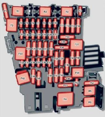
Audi A4 (2017) – fuse box diagram

Audi A4 (2017) – fuse box diagram

Year of production: 2017

Fuse assignment – driver’s/front passenger’s footwell

Audi A4 - fuse box diagram - driver's front passenger's footwell
Audi A4 – fuse box diagram – driver’s front passenger’s footwell

Front passenger ‘s footwell (right -hand drive vehicle)

Audi A4 - fuse box diagram - driver's front passenger's footwell (right hand drive vehicle)
Audi A4 – fuse box diagram – driver’s front passenger’s footwell (right hand drive vehicle)

Fuse panel A (brown)

Number Electric equipment
1
2 Mass airflow sensor, camshaft adjustment
3 Exhaust doors, fuel injectors, radiator inlet
4 Vacuum pump, hot water pump, particulate sensor, biodiesel sensor
5 Brake light sensor
6 Engine valves
7 Heated oxygen sensor, mass airflow sensor
8 Water pump, high pressure pump, high pressure regulator valve
9 Hot water pump
10 Oil pressure sensor, oil temperature sensor
11 Clutch pedal position sensor
12 Engine valves
13 Radiator fan
14 Fuel injectors
15 Ignition coils
16 Fuel pump


Fuse panel B (red)

Number Electric equipment
1 Anti-theft alarm system
2 Engine control module
3 Lumbar support
4 Automatic transmission selector mechanism
5 Horn
6 Electromechan ical park ing brake
7 Gateway control module
8 Interior headl iner lights
9
10 Airbag control module
11 Electronic Stabilization Control (ESC
12 Diagnostic connector, light/rain sensor
13 Climate control system
14 Right front door control module
15 A/C compressor

Fuse panel C (black)

Number Electric equipment
1 Front seat heating
2 Windshield wipers
3 Left head light electronics
4 Panorama glass roof/ sliding/t ilting sunroof
5 Left front door control module
6 Sockets
7 Right rear door control module
8
9 Right headlight electronics
10 Windshield washer system/headlight washer system
11 Left rear door control module

Fuse panel D (black)

Number Electric equipment
1 Seat ventilation, rearv iew mirror, rear climate control system controls
2 Gateway, climate control system
3 Sound actuator/exhaust sound tuning
4 Clutch pedal position sensor
5 Engine start
6
7
8 Homelink
9 Adaptive cruise control
10
11 Video camera
12 Matrix LED headlight/right LED headlight
13 Matrix LED headlight/left LED headlight
14 Rear window wiper

Fuse panel E (red)

Number Electric equipment
1 Ignition coils
2 Natural gas tank valves
3
4
5 Engine mount
6 Automat ic transmission
7 Instrument panel
8 Climate control system (blower)
9
10 Dynamic steering
11 Engine start

Driver’s side cockpit fuse assignment

Audi A4 - fuse box diagram - driver's side cocpit
Audi A4 – fuse box diagram – driver’s side cocpit
Number Electric equipment
1
2 Telephone
3
4 Head-up display
5 Audi music interface
6 Front climate control system controls
7 Steering column lock
8 Infotainment syst em display
9 Instrument cluster
10 Infotainment unit
11 Light switch
12 Steering column electronics
13
14 Infotainment system
15
16 Steering wheel heating

Left luggage compartment fuse assignment

Audi A4 - fuse box diagram - luggage compartment
Audi A4 – fuse box diagram – luggage compartment

Fuse panel A (black)

Number Electric equipment
1
2 Windshield defroster
3 Windshield defroster
4
5 Suspension control
6 Automatic transmission
7 Rear window defogger
8 Rear seat heating
9 Tail lights
10 Left safety belt tensioner
11 Central locking
12 Electric luggage compartment lid


Fuse panel B (red)

Number Electric equipment
Not assigned


Fuse panel C (brown)

Number Electric equipment
1
2 Telephone
3 Lumbar support
4 Audi side assist
5
6
7
8
9
10
11
12 Homelink
13 Rearview camera, peripheral cameras
14 Right tail lights
15
16 Right safety belt tensioner


Fuse panel E (red)

Number Electric equipment
1
2 Sound-amplifier
3 AdBlue
4
5 Trailer hitch (right light)
6
7 Trailer hitch
8 Trailer hitch (left light)
9 Trailer hitch (socket)
10 Sport differential
11 Ad Blue


WARNING: Terminal and harness assignments for individual connectors will vary depending on vehicle equipment level, model, and market.

Audi A4 (2014 – 2016) – fuse box diagram

Audi A4 (2014 – 2016) – fuse box diagram

Year of production: 2014, 2015, 2016

Instrument panel (driver’s side)

Audi A4 - fuse box diagram - left cocpit
Audi A4 – fuse box diagram – left cocpit

Fuse panel A (black)

Number Electric equipment Ampere rattings [A]
1 Dynamic steering 5
2 Electronic Stabilization Control (module) 5
3 A/C system pressure sensor, electromechanical parking brake, Homelink, automatic dimming interior rear view mirror, air quality/outside air sensor, Electronic Stabilization Control (button) 5
4
5 Sound actuator 5
6 Headlight range control/head light (cornering light) 5/7,5
7 Headlight (cornering light) 7,5
8 Control modules (electromechanical parking brake, shock absorber, quattro sport), DCDC converter 5
9 Adaptive cruise control 5
10 Shift gate/clutch sensor 5
11 Side assist 5
12 Headlight range control, parking system 5
13 Airbag 5
14 Rear wiper (allroad) 15
15 Auxiliary fuse (instrument panel) 10
16 Auxiliary fuse terminal 15 (engine area) 40


Fuse panel B (brown)

Number Electric equipment Ampere rattings [A]
1
2 Brake light sensor 5
3 Fuel pump 25
4 Clutch sensor 5
5 Left seat heating with/without seat ventilation 15/30
6 Electronic Stabilization Control (electric) 5
7 Horn 15
8 Front left door (window regulator, central locking, mirror, switch, lighting) 30
9 Windshield wiper motor 30
10 Electronic Stabilization Control (valves) 25
11 Two-door models: rear left window regulator, Four-door models: rear left door (window regulator, central locking, switch, lighting) 30
12 Rain and light sensor 5

Fuse panel C (red)

Number Electric equipment Ampere rattings [A]
1
2
3 Lumbar support 10
4 Dynamic steering 35
5 Interior lighting (Cabriolet) 5
6 Windshield washer system, headlight washer system 35
7 Vehicle electrical system control module 1 20
8 Vehicle electrical system control module 1 30
9 Left rear window regulator motor (Cabriolet)/sunroof 7,5/20
10 Vehicle electrical system control module 1 30
11 Right rear window regulator (Cabriolet)/sun shade motor 7,5/20
12 Anti-theft alarm warning system 5

Instrument panel (right)

Audi A4 - fuse box diagram - right cocpit
Audi A4 – fuse box diagram – right cocpit

Fuse carrier A (black)

Number Electric equipment Ampere rattings [A]
1
2
3
4
5 Steering column switch module 5
6
7 Terminal 15 diagnostic connector 5
8 Gateway (Databus diagnostic interface) 5
9 Supplementary heater 5
10
11
12

Fuse panel B (brown)

Number Electric equipment Ampere rattings [A]
1 CD-/DVD player 5
2 Wi-Fi 5
3 MMI/Radio 5/20
4 Instrument cluster 5
5 Gateway (instrument cluster control module) 5
6 Ignition lock 5
7 Light switch 5
8 Climate control system blower 40
9 Steering column lock 5
10 Climate control system 10
11 Terminal 30 diagnostic connector 10
12 Steering column switch module 5

Luggage compartment

Audi A4 - fuse box diagram - luggage compartment
Audi A4 – fuse box diagram – luggage compartment

Fuse panel A (black)

Number Electric equipment Ampere rattings [A]
1 30
2 Rear window heater (Cabriolet) 30
3 Power top latch (Cabriolet) 30
4 Power top hydraulics (Cabriolet) 50


Fuse panel B (black)

Number Electric equipment Ampere rattings [A]
1 Luggage compartment lid control module (all road) / Power top control module (Cabriolet) 30/10
2 Retractable rear spoiler (RS 5 Coupe) 10
3
4
5 Electromechanical parking brake 5
6 Electronic damping control 15
7 Electromechanical parking brake 30
8 Rear exterior lighting 30
9 Quattro Sport 35
10 Rear exterior lighting 30
11 Central locking 20
12 Terminal 30 5


Fuse panel C (brown)

Number Electric equipment Ampere rattings [A]
1 Luggage compartment lid control module (allroad) 30
2 12-volt socket, cigarette lighter 20
3 DCDC converter path 1 40
4 DCDC converter path 2, DSP amplifier, radio 40
5 Right upper cabin heating (Cabriolet) 30
6
7 Electromechanical parking brake 30
8
9 Right front door (window regulator, central locking, mirror, switch, lighting) 30
10 Left upper cabin heating (Cabriolet) 30
11 Two-door models : rear right window regu lator, Four-door models : rear right door (window regulator, central locking, switch , lighting) 30
12 Cell phone prep 5


Fuse panel E (black)

Number Electric equipment Ampere rattings [A]
1 Right front seat heating 15
2
3
4 MMI 7,5
5 Radio 5
6 Rear view camera 5
7 Rear window heater (allroad) 30
8 Rear Seat Entertainment 5
9
10
11
12


WARNING: Terminal and harness assignments for individual connectors will vary depending on vehicle equipment level, model, and market.

Audi A4 (2013) – fuse box diagram

Audi A4 (2013) – fuse box diagram

Year of production: 2013

Instrument panel (driver’s side)

Audi A4 - fuse box diagram - left cocpit
Audi A4 – fuse box diagram – left cocpit

Fuse panel A (black)

Number Electric equipment Ampere rattings [A]
1 Dynamic steering 5
2 ESC control module 5
3 A/C system pressure sensor, electromechanical parking brake, Homelink, automatic dimming interior rear view mirror, air quality/outside air sensor, ESC button 5
4
5 Sound actuator/exhaust sound tuning 5/15
6 Headlight range control systern/cornering light 5/7,5
7 Headlight (cornering light) 7,5
8 Control modules (electromechanical parking brake, shock absorber, quattro sport, trailer hitch), DCDC converter 5
9 Adaptive cruise control 5
10 Shift gate 5
11 Side assist 5
12 Headlight range control, parking system 5
13 Airbag 5
14 Rear wiper (allroad) 15
15 Auxiliary fuse (instrument panel) 10
16 Auxiliary fuse terminal 15 (engine area) 40


Fuse panel B (brown)

Number Electric equipment Ampere rattings [A]
1
2 Brake light sensor 5
3 Fuel pump 25
4 Clutch sensor 5
5 Left seat heating with/without seat ventilation 15/30
6 ESC 5
7 Horn 15
8 Front left door (window regulator, central locking, mirror, switch, lighting) 30
9 Wiper motor 30
10 ESC 25
11 Two-door models: rear left window regulator, Four-door models: rear left door (window regulator, central locking, switch, lighting) 30
12 Rain and light sensor 5

Fuse panel C (red)

Number Electric equipment Ampere rattings [A]
1
2
3 Lumbar support 10
4 Dynamic steering 35
5 Interior lighting (Cabriolet) 5
6 Windshield washer system, headlight washer system 35
7 Vehicle electrical system control module 1 20
8 Vehicle electrical system control module 1 30
9 Left rear window regulator motor (Cabriolet)/sunroof 7,5/20
10 Vehicle electrical system control module 1 30
11 Right rear window regulator (Cabriolet)/sun shade motor 7,5/20
12 Anti-theft alarm warning system 5

Instrument panel (right)

Audi A4 - fuse box diagram - right cocpit
Audi A4 – fuse box diagram – right cocpit

Fuse carrier A (black)

Number Electric equipment Ampere rattings [A]
1
2
3
4
5 Steering column switch module 5
6
7 Terminal 15 diagnostic connector 5
8 Gateway (Databus diagnostic interface) 5
9 Supplementary heate r 5
10
11
12

Fuse panel B (brown)

Number Electric equipment Ampere rattings [A]
1 CD-/DVD player 5
2 Wi-Fi 5
3 MMI/Radio 5/20
4 Instrument cluster 5
5 Gateway (instrument cluster control module) 5
6 Ignition lock 5
7 Light switch 5
8 Climate control system blower 40
9 Steering column lock 5
10 Climate control system 10
11 Terminal 30 diagnostic connector 10
12 Steering column switch module 5

Luggage compartment

Audi A4 - fuse box diagram - luggage compartment
Audi A4 – fuse box diagram – luggage compartment

Fuse panel B (black)

Number Electric equipment Ampere rattings [A]
1 Luggage compartment lid control module (all road) / Power top control module (Cabriolet) 30/10
2 Trailer cont rol module or retractable rear spoiler (RS 5 Coupe) 15
3 Trailer control module 20
4 Trailer control module 20
5 Electromechanical parking brake 5
6 Electronic damping control 15
7 Electromechanical parking brake 30
8 Rear exterior lighting 30
9 Quattro Sport 35
10 Rear exterior lighting 30
11 Vehicle electrical system control module 20
12 Terminal 30 5


Fuse panel C (brown)

Number Electric equipment Ampere rattings [A]
1 Luggage compartment lid control module (allroad) 30
2 12-volt socket, cigarette lighter 20
3 DCDC converter path 1 40
4 DCDC converter path 2, DSP amplifier, radio 40
5 Right upper cabin heating (Cabriolet) 30
6
7 Electromechanical parking brake 30
8
9 Rig ht front door (window regulator, central locking, mirror, switch, lighting) 30
10 Left upper cabin heating (Cabriolet) 30
11 Two-door models : rear right window regu lator, Four-door models : rear right door (window regulator, central locking, switch , lighti ng) 30
12 Cell phone prep 5


Fuse panel E (black)

Number Electric equipment Ampere rattings [A]
1 Right front seat heating 15
2
3
4 MMI 7,5
5 Radio 5
6 Rear view camera 5
7 Rear window heater (allroad) 30
8 Rear Seat Entertainment 5
9
10
11
12


WARNING: Terminal and harness assignments for individual connectors will vary depending on vehicle equipment level, model, and market.

Audi A4 (2011 – 2012) – fuse box diagram

Audi A4 (2011 – 2012) – fuse box diagram

Year of production: 2011, 2012

Instrument panel (driver’s side)

Audi A4 - fuse box diagram - left cocpit
Audi A4 – fuse box diagram – left cocpit

Fuse panel A (black)

Number Electric equipment Ampere rattings [A]
1 Dynamic steering 5
2
3 Homelink 5
4
5 Climate control 5
6 Right headlight range adjustment 5
7 Left headlight range adjustment 5
8 Vehicle electrical system control module 1 5
9 Adaptive Cruise Control 5
10 Shift gate 5
11 Heater washer fluid nozzles 5
12 Climate control 5
13 Cell phone prep 5
14 Airbag 5
15 Terminal 15 25
16 Terminal 15 engine 40


Fuse panel B (brown)

Number Electric equipment Ampere rattings [A]
1 Automatic dimming interior rearview mirror 5
2 Clutch sensor 5
3 Gasoline fuel pump 25
4
5 Left seat heating with/without seat heating 15
30
6 Electronic Stabilization Program 10
7 Horn 25
8 Left door window regulator motor 30
9 Wiper motor 30
10 Electronic Stabilization Program 25
11 Left doors 15
12 Rain and light sensor 5

Fuse panel C (red)

Number Electric equipment Ampere rattings [A]
1
2
3 Lumbar support 10
4 Dynamic steering 35
5 Antenna (Avant) 5
6 Vehicle electrical system control module 1 35
7 Vehicle electrical system control module 1 20
8 Vehicle electrical system control module 1 30
9 Sunroof 20
10 Vehicle electrical system control module 1 30
11 Sunroof shade (Avant) 20
12 Convenience electronics 5

Instrument panel (right)

Audi A4 - fuse box diagram - right cocpit
Audi A4 – fuse box diagram – right cocpit

Fuse carrier A (black)

Number Electric equipment Ampere rattings [A]
1
2
3
4
5 Steering column switch module 5
6 Electronic Stabilisation Program 5
7 Terminal 15 diagnostic connector 5
8 Gateway (Databus diagnostic interface) 5
9
10
11
12

Fuse panel B (brown)

Number Electric equipment Ampere rattings [A]
1 CD-/DVD player 5
2 Audi drive select switch module 5
3 MMI/Radio 5
20
4 Instrument cluster 5
5 Gateway (instrument cluster control module) 5
6 Ignition lock 5
7 Rotary light switch 5
8 Climate control system blower 40
9 Steering column lock 5
10 Climate control 10
11 Terminal 30 diagnostic connector 10
12 Steering column switch module 5

Luggage compartment

Audi A4 - fuse box diagram - luggage compartment
Audi A4 – fuse box diagram – luggage compartment

Fuse panel B (black)

Number Electric equipment Ampere rattings [A]
1 Luggage compartment lid control module (Avant) 30
2 Trailer control module 15
3 Trailer control module 20
4 Trailer control module 20
5 Electromechanical parking brake 5
6 Electronic damping control 15
7 Electromechanical parking brake 30
8 Vehicle electrical system control module 2 30
9 Quattro Sport 35
10 Vehicle electrical system control module 2 30
11 Vehicle electrical system control module 20
12 Terminal 30 5


Fuse panel C (brown)

Number Electric equipment Ampere rattings [A]
1 Luggage compartment lid control module 30
2 Right front seat heating 15
3 DCDC converter path 1 40
4 DCDC converter path 2 40
5 Socket 30
6
7 Electromechanical parking brake 30
8 Rear seat heating 30
9 Passenger side door con rol module 30
10
11 Passenger side door control module 15
12


Fuse panel D (red)

Number Electric equipment Ampere rattings [A]
1 Rear center console outlet 15
2 Front center console outlet 15
3 Luggage compartment outlet 15
4 Cigarette lighter 15
5 V6 FSI 5
6 Rear Seat Entertainment supply 5
7 Parking system 7,5
8 Rear wiper (Avant) 15
9 Electromechanical parking brake switch 5
10 Audi side assist 5
11 Rear seat heating 5
12 Terminal 15 control modules 5

Fuse panel E (black)

Number Electric equipment Ampere rattings [A]
1
2
3 DSP amplifier, radio 30
20
4 MMI 7,5
5 Radio/navigation/cell phone prep 7,5
6
7 Cell phone prep 5
8
9
10
11
12


WARNING: Terminal and harness assignments for individual connectors will vary depending on vehicle equipment level, model, and market.

Audi A4 (2010) – fuse box diagram

Audi A4 (2010) – fuse box diagram

Year of production: 2010

Instrument panel (driver’s side)

Fuse panel A (black)

Number Electric equipment Ampere rattings [A]
1 Dynamic steering 5
2
3 Homelink 5
4
5 Climate control 5
6 Right headlight range adjustment 5
7 Left headlight range adjustment 5
8 Vehicle electrical system control module 1 5
9 Adaptive Cruise Control 5
10 Shift gate 5
11 Heater washer fluid nozzles 5
12 Climate control 5
13 Cell phone prep 5
14 Airbag 5
15 Terminal 15 25
16 Terminal 15 engine 40


Fuse panel B (brown)

Number Electric equipment Ampere rattings [A]
1 Automatic dimming interior rearview mirror 5
2 Clutch sensor 5
3 Gasoline fuel pump 25
4 Auxiliary water pump 3.2L FSI 5
5 Left seat heating with/without seat heating 15
30
6 Electronic Stabilization Program 10
7 Horn 25
8 Left door window regulator motor 30
9 Wiper motor 30
10 Electronic Stabilization Program 25
11 Left doors 15
12 Rain and light sensor 5

Fuse panel (red)

Number Electric equipment Ampere rattings [A]
1
2
3 Lumbar support 10
4 Dynamic steering 35
5 Climatized cupholder 5
6 Vehicle electrical system control module 1 35
7 Vehicle electrical system control module 1 20
8 Vehicle electrical system control module 1 30
9 Panorama sunroof 20
10 Vehicle electrical system control module 1 30
11 Panorama sunroof shade 20
12 Convenience electronics 5

Instrument panel (right)

Fuse carrier (black)

Number Electric equipment Ampere rattings [A]
1
2
3
4
5 Steering column switch module 5
6 Electronic Stabilisation Program 5
7 Terminal 15 diagnostic connector 5
8 Gateway 5
9
10
11
12

Fuse panel (brown)

Number Electric equipment Ampere rattings [A]
1 CD drive 5
2 Audi drive select switch module 5
3 MMI/Radio 5
20
4 Instrument cluster 5
5 Gateway 5
6 Ignition lock 5
7 Rotary light switch 5
8 Climate control system blower 40
9 Steering column lock 5
10 Climate control 10
11 Terminal 30 diagnostic connector 10
12 Steering column switch module 5

Luggage compartment

Fuse panel B (black)

Number Electric equipment Ampere rattings [A]
1 Luggage compartment lid control module (Avant) 30
2 Trailer control mod ule 15
3 Trailer control mod ule 20
4 Trailer control mod ule 20
5 Electromechanical parking brake 5
6 Electronic damping control 15
7 Electromechanical parking brake 30
8 Vehicle electrical system control module 2 30
9 Quattro Sport 35
10 Vehicle electrical system control module 2 30
11 Vehicle electrical system control module 2 20
12 Terminal 30 5


Fuse panel C (brown)

Number Electric equipment Ampere rattings [A]
1 Luggage compartment lid control module 30
2 Right front seat heating 15
3 DCDC converter path 1 40
4 DCDC converter path 2 40
5 Socket 30
6
7 Electromechanical parking brake 30
8 Rear seat heating 30
9 Passenger side door con rol module 30
10
11 Passenger side door control module 15
12


Fuse panel D (red)

Number Electric equipment Ampere rattings [A]
1 Rear center console outlet 15
2 Front center console outlet 15
3 Luggage compartment outlet 15
4 Cigarette lighter 15
5 V6 FSI 5
6 Rear Seat Entertainment supply 5
7 Parking system 7,5
8 Rear wiper (Avant) 15
9 Electromechanical park ing brake switch 5
10 Audi side assist 5
11 Rear seat heating 5
12 Terminal 15 control modules 5

Fuse panel E (black)

Number Electric equipment Ampere rattings [A]
1
2
3 DSP amplifier, radio 30
20
4 MMI 7,5
5 Radio/navigation/cell phone prep 7,5
6 Rearview camera 5
7
8
9
10
11
12


WARNING: Terminal and harness assignments for individual connectors will vary depending on vehicle equipment level, model, and market.

Pontiac Pursuit (2006) – fuse box diagram

Pontiac Pursuit (2006) – fuse box diagram

Year of production: 2006

Floor Console Fuse Block

The floor console fuse box is located on the passenger’s side of the floor console under the instrument panel.

Pontiac Pursuit - fuse box diagram - floor console
Pontiac Pursuit – fuse box diagram – floor console
Fuses Usage
1 Fuse Puller
2 Spare
3 Spare
4 Spare
5 Spare
6 Amplifer
7 Cluster
8 Ignition Switch, PASS-Key III+
9 Stoplamp
10 Heating, Ventilation, Air Conditioning, PASS-Key III+
11
12 Spare
13 Airbag
14 Spare
15 Windshield Wiper
16 Climate Control System, Cluster
17
18
19 Electric Power Steering, steering Wheel control
20 Sunroof
21 Spare
22
23 Audio System
24 Sensing and Diagnostic Module (Airbag)
25 Engine Control Module, Transmission Control Module
26 Door Locks
27 Interior Lights
28
29 Power Windows


Relays Usage
30 Climate Control System
31
32 Retained Accessory Power


Engine Compartment Fuse Block

The engine compartment fuse block is located on the driver’s side of the vehicle.

Pontiac Pursuit - fuse box diagram - engine compartment
Pontiac Pursuit – fuse box diagram – engine compartment (2.2L engine (L61) and 2.4L engine (LE5))
Number Usage
SPARES Spares
Blank
Blank
RDFG Rear Defogger
COOL/FAN2 Cooling Fan 2
CRNK Starter
COOL/FAN1 Engine Cooling Fan
BCM3 Body Control Module 3
BCM2 Body Control Module 2
FOG LP Fog Lamps
HORN Horn
RH HI BEAM Passenger’s Side High Beam
LH HI BEAM Driver’s Side High Beam
RH LO BEAM Passenger’s Side Low Beam
LH LO BEAM Driver’s Side Low Beam
Blank
FUEL PUMP Fuel Pump
EMISN Emissions
Blank
INJ Injectors
Blank
ABS Anti-lock Brake System
PCM/ECM Powertrain control Module/Engine Control Module
EPS Electric Power Steering
PRK LPS Park Lamps
WPR Windshield Wiper
IP IGN Ignition
A/C CLTCH Air Conditioning Clutch
AIR SOL Air Solenoid
ABS2 Anti-lock Brake System 2
PRK/NEUT Park, Neutral
ECM/TRANS Engine Control Module, Transmission
BCK UP Back-Up Lamps
TRUNK/OUTLET Trunk, Accessory Power Outlet
Blank
Blank
S BAND/ONSTAR Audio, OnStar
Blank
LTR Cigarette Lighter
MIR(S) Mirrors
HTD SEATS Heated Seats
CNSTR VENT Canister Vent


Relays Usage
RDFG Rear Defogger
COOL/FAN2 Cooling Fan 2
WPR2 Windshield Wiper 2
CRNK Starter
COOL/FAN1 Cooling Fan 1
FUEL PMP Fuel Pump
WPR1 Windshield Wiper 1
PWR/TRN Powertrain
AIR PMP Air Pump
A/C CLTCH Air Conditioning Clutch
AIR SOL Air Solenoid
RUN/CRANK Run, Crank

WARNING: Terminal and harness assignments for individual connectors will vary depending on vehicle equipment level, model, and market.

Pontiac Pursuit (2005) – fuse box diagram

Pontiac Pursuit (2005) – fuse box diagram

Year of production: 2005

Floor Console Fuse Block

The floor console fuse block is located on the passenger’s side of the floor console under the instrument panel.
Pontiac Pursuit - fuse box diagram - floor console
Pontiac Pursuit – fuse box diagram – floor console
Fuses Usage
1 Fuse Puller
2
Spare
3 Spare
4 Spare
5 Spare
6 Amplifer
7
Cluster
8 Ignition Switch
9 Stoplamp
10 Heating, Ventilation, Air Conditioning
11
12
Spare
13
Airbag
14
Spare
15 Windshield Wiper
16
Climate Control System, Cluster, Brake Transmission Shift Interlock
17
18
19
Electric Power Steering, Steering Wheel Contro
20
Sunroof
21
Spare
22
23
24 Sensing and Diagnostic Module
25
Engine Control Module, Transaxle Control Module
26 Door Locks
27 Interior Lights
28 Audio System
29 Power Windows

Relays Usage
30 Ignition 3
31
32 Retained Accessory Power

Engine Compartment Fuse Block

The engine compartment fuse block is located on the driver’s side of the vehicle.

Pontiac Pursuit - fuse box diagram - engine compartment
Pontiac Pursuit – fuse box diagram – engine compartment
Number Usage
SPARES
Spares
RDFG Rear Defogger
COOL/FAN2 Cooling Fan 2
CRNK Starter
COOL/FAN1 Engine Cooling Fan
BCM3 Body Control Module 3
BCM2 Body Control Module 2
FOG LP Fog Lamps
HORN Horn
RH LO BEAM Passenger’s Side Low Beam
LH LO BEAM Driver’s Side Low Beam
RH HI BEAM Passenger’s Side High Beam
LH HI BEAM Driver’s Side High Beam
FUEL PUMP Fuel Pump
EMISN Emissions
INJ Injectors
ABS Anti-lock Brake System
PCM/ECM
Powertrain Control Module/Engine Control Module
EPS Electric Power Steering
PRK LPS Park Lamps
WPR Windshield Wiper
IP IGN Ignition
A/C CLTCH Air Conditioning Clutch
AFTRCOOL Aftercooler
ABS2 Anti-lock Brake System
PRK/NEUT Park, Neutral
ECM/TRANS
Engine Control Module, Transmissio
BCK UP Back-Up Lamps
TRUNK/OUTLET Trunk, Accessory Power Outlet
S BAND/ONSTAR Audio, OnStar
LTR Cigarette Lighter
MIR(S) Mirrors
HTD SEATS Heated Seats
CNSTR VENT Canister Vent

Relays Usage
RDFG
Rear Defogger
COOL/FAN2 Cooling Fan 2
WPR2 Windshield Wiper 2
CRNK
Starter
COOL/FAN1 Cooling Fan 1
FUEL PMP Fuel Pump
WPR1 Windshield Wiper 1
COOL SER/PAR
PWR/TRN Powertrain
A/C CLTCH Air Conditioning Clutch
AFTRCOOL
RUN/CRANK Run, Crank

WARNING: Terminal and harness assignments for individual connectors will vary depending on vehicle equipment level, model, and market.

Audi A4 (2008) – fuse box diagram

Audi A4 (2008) – fuse box diagram

Year of production: 2008

Instrument panel (driver’s side)

Fuse carrier (black)

Number Electric equipment Ampere rattings [A]
1 Dynamic steering 5
2 Clutch sensor 5
3 Garage door opener 5
4 Audi lane assist 10
5 Air conditioner 5
6 Headlight range control (right) 5
7 Headlight range control (left) 5
8 Control unit 1 for vehicle’s electrical system 5
9 Interior mirrors 5
10 Selector gate 5
11 Heated washer jets 5
12 Air conditioner 5


Fuse carrier (brown)

Number Electric equipment Ampere rattings [A]
1
2 Clutch sensor 5
3 Fuel pump (diesel/petrol) 20
25
4 Auxiliary water pump (3.2 FSI) 5
5 Seat heating (left-side) with/without seat ventilation 30
6 Electronic stabilisation program 10
7 Horn 25
8 Electric window motor (left door) 30
9 Wiper motor 30
10 Electronic stabilisation program 25
11 Door control unit (driver’s side) 15
12 Rain and light sensor 5

Fuse carrier (red)

Number Electric equipment Ampere rattings [A]
1
2
3 Lumbar support 10
4 Dynamic steering 35
5 Interior light 5
6 Control unit 1 for vehicle’s electrical system 35
7 Control unit 1 for vehicle’s electrical system 30
8 Control unit 1 for vehicle’s electrical system 30
9 Tilting panorama roof/sun roof 20
10 Control unit 1 for vehicle’s electrical system 30
11
12 Convenience electronics 5

Instrument panel (passenger’s side)

Fuse carrier (black)

Number Electric equipment Ampere rattings [A]
1
2
3
4
5 Steering column switch module 5
6 Electronic Stabilisation Program 5
7 Diagnostic connector 5
8 Gateway (diagnostic interface for data bus) 5
9
10
11
12

Fuse carrier (brown)

Number Electric equipment Ampere rattings [A]
1 CD drive 5
2 Switch module for Audi drive select 5
3 MMI/Radio 10
20
4 Light switch 5
5 Control unit for instrument cluster 5
6 Ignition lock 5
7
8 Air conditioner blower 40
9 Steering column lock 5
10 Air conditioner 10
11 Diagnostic connector 10
12 Steering column switch module 5

Luggage compartment

Fuse carrier (black)

Number Electric equipment Ampere rattings [A]
1
2 Control unit for trailer 15
3 Control unit for trailer 20
4 Control unit for trailer 20
5 Electronic parking brake 5
6 Electronic suspension control 15
7 Electro-mechanical parking brake 30
8 Control unit 2 for vehicle’s electrical system 30
9
10 Control unit 2 for vehicle’s electrical system 30
11 Control unit 2 for vehicle’s electrical system 20
12


Fuse carrier (brown)

Number Electric equipment Ampere rattings [A]
1 Electrical socket 15
2
3 Radio/navigation 7,5
4 Control unit for digital sound system 30
5 MMI 5
6 Door control unit (driver’s side) 30
7 Electro-mechanical parking brake 30
8 Seat heating, rear 30
9 Door control unit (passenger side) 30
10 Remote control receiver for auxiliary heating 5
11 Door control unit (passenger side) 15
12 Control unit for reversing camera 5


Fuse carrier (red)

Number Electric equipment Ampere rattings [A]
1 Socket, centre console, rear 15
2 Socket, centre console, front 15
3 Socket, luggage compartment 15
4 Cigarette lighter 15
5 Parking aid 5
6 Phone pre-installation without handsfree system (VDA interface) 5
7 Control unit for adaptive cruise control 15
8
9 EPB switch (electro-mechanical parking brake) 5
10 Lane change assist feature 5
11 Seat heating, rear 5
12 Airbag 5

WARNING: Terminal and harness assignments for individual connectors will vary depending on vehicle equipment level, model, and market.

Audi S3 (2016) – fuse box diagram

Audi S3 (2016) – fuse box diagram

Year of production: 2016

Instrument panel

Audi A3 - fuse box diagram - instrument panel
Audi S3 – fuse box diagram – instrument panel
Number Equipment
F1 Engine components
F2 Seat adjustment
F3 Hydraulic pump cover (Cabriolet)
F4 MM controls, MMI-components
F5 Gateway
F6 Selector lever (automatic transmission)
F7 Climate/heating control, selector lever (automatic transmission), parking heater, rear window heater relay coil
F8 Diagnosis, electromechanical parking brake switch, light switch , rain and light sensor, interior lighting communication box (Plug-in hybrid drive*) anti-theft alarm system
F9 Steering column switch module
F10 Display
F11 Reversible driver’s side safety belt tensioners
F12 MMI area
F13 Adaptive dampers control module/ service plug (Plug-in hybrid drive”)
F14 Climate control system blower
F15 Electronic steering column lock
F16 MMI area
F17 Instrument cluster
F18 Rearview camera
F19 Convince key system control module, tank system
F20 Tank system
F21
F22
F23 Exterior lighting, heated washer fluid nozzles
F24 Panorama sunroof/ power top control modu le, power top latch (Cabriolet)
F25 Door/driver’s side doors (for example power windows)
F26 Seat heating
F27 Sound-amplifier
F28 Power top control module, electronics (Cabriolet)
F29 Interior lights
F30
F31 Exterior lighting
F32 Driver assistance systems
F33 Airbag
F34 Button illumination, coils for upper cabin heating relay (Cabriolet) and socket relay, interior sound, reversing light switch, ternperature sensor
F35 Function lighting, diagnosis, headlight range control system, air quality sensor, automatic dimming rearview mirror
F36 Right cornering light/ right LED-headlight
F37 Left cornering light/ left LED-head light
F38 High-voltage battery (Plug-in hybrid drive*)
F39 Door/front passenger’s side doors (for example, power windows)
F40 Sockets
F41 Reversible front passenger’s side safety belt tensioners
F42 Central locking components, windshield washer system
F43 Headlights , lighting
F44 All wheel drive
F45
F46
F47 Rear window wiper
F48 Outer noise amplifier (Plug-in hybrid drive*)
F49 Starter, clutch sensor, headlight relay coil, high-voltage battery (Plug-in hybrid drive*)
F50
F51
F52
F53 Rear window defogger


Engine compartment

Audi A3 - fuse box diagram - engine compartment
Audi S3 – fuse box diagram – engine compartment
Number Equipment
F1 ESC control module
F2 ESC control module
F3 Engine control module (gasoline/diesel)
F4 Engine cooling, engine components, auxiliary heater coil relay (1+2), secondary air injection pump relay
F5 Engine components, tank system
F6 Brake light sensor
F7 Engine components, water pumps
F8 Oxygen sensor
F9 Engine components, exhaust door, glow time control module, SULEV valve
F10 Fuel injectors, fuel control module
F11 Auxiliary heater heating element2
F12 Auxiliary heater heating element3
F13 Automatic transmission control module
F14
F15 Horn
F16 Ignition coil/ power electronics (Plug-in hybrid drive*)
F17 ESC contro l module, engine control module
F18 Terminal 30 (reference voltage)
F19 Windshield wipers
F20 Horn
F21
F22 Terminal SO diagnosis
F23 Starter
F24 Auxiliary heater heating element 1, brake booster (Plug-in hybrid drive*)
F25
F26
F27
F28
F29
F30
F31 Vacuum pump/water pump (Plug-in hybrid drive*)
F32 LED headlights
F33 Brake booster memory (Plug-in hybrid drive*)
F34 Brake booster memory (Plug-in hybrid drive*)
F34 Relay (Plug-in hybrid drive*)

WARNING: Terminal and harness assignments for individual connectors will vary depending on vehicle equipment level, model, and market.

Audi S3 (2015) – fuse box diagram

Audi S3 (2015) – fuse box diagram

Year of production: 2015

Instrument panel

Audi A3 - fuse box diagram - instrument panel
Audi S3 – fuse box diagram – instrument panel
Number Equipment Ampere rating [A]
F1 Engine components 30
F2 Seat adjustment 10
F3 Hydraulic pump cover (Cabriolet) 40
F4 MM controls, MMI-components 7,5
F5 Gateway 5
F6 Anti-theft alarm system 5
F7 Climate/heating control, selector lever (automatic transmission), parking heater, rear window heater relay coil 10
F8 Diagnosis, electrical parking brake switch, light switch, rain/light sensor, interior lighting 10
F9 Steering column switch module 1
F10 Display 5
F11 Reversible driver’s side safety belt tensioners 25
F12 MMI area 15
20
F13 Adaptive dampers control module 20
F14 Climate control system blower 30
F15 Electronic steering column lock 10
F16 MMI area 7,5
F17 Instrument cluster 5
F18 Rearview camera 7,5
F19 Convince key system control module, tank system 7,5
F20 Tank system 7,5
F21
F22
F23 Exterior lighting, heated washer fluid nozzles 40
F24 Panorama sunroof/ power top control modu le, power top latch (Cabriolet) 20
30
F25 Door/dr iver’s side doors (for example power windows) 30
F26 Seat heating 30
F27 Sound-amplifier 30
F28 Power top control module, electronics (Cabriolet) 5
F29 Interior lights 7,5
F30
F31 Exterior lighting 40
F32 Driver assistance systems 7,5
F33 Airbag 5
F34 Button illumination, coils for upper cab in heating relay (Cabriolet) and socket relay, interior sound, back-up light switch, temperature sensor, oil level sensor 7,5
F35 Diagnosis, headlight range control system, air quality sensor, automatic dimming rearview mirror 10
F36 Right cornering light/ right LED-headlight 15
F37 Left cornering light/ left LED-head light 15
F38
F39 Door/front passenger’s side doors (for example, power windows) 30
F40 Sockets 20
F41 Reversible front passenger’s side safety belt tensioners 25
F42 Central locking components, windshield washer system 40
F43 Headlights , lighting 30
F44 All wheel drive 15
F45
F46
F47
F48
F49 Starter, clutch sensor, head light relay coil 5
F50
F51
F52
F53 Rear window defogger 30


Engine compartment

Audi A3 - fuse box diagram - engine compartment
Audi S3 – fuse box diagram – engine compartment
Number Equipment Ampere rating [A]
F1 ESC control module 40
F2 ESC control module 40
F3 Engine control module (gasoline/diesel) 15
30
F4 Engine cooling, engine components, auxiliary heater coil relay (1+2), secondary air injection pump relay 5
10
F5 Engine components, tank system 7,5
10
15
F6 Brake light sensor 5
F7 Engine components, water pumps 7,5
10
15
F8 Oxygen sensor 10
15
F9 Engine components, exhaust door, glow time control module, SULEV valve 5
10
20
F10 Fuel injectors, fuel control module 15
20
F11 Auxiliary heater heating element2 40
F12 Auxiliary heater heating element3 40
F13 Automatic transmission control module 15
30
F14
F15 Horn 15
F16 Ignit ion coil 5
20
F17 ESC contro l module, engine control module 7,5
F18 Terminal 30 (reference voltage) 5
F19 Windshield wipers 30
F20 Horn 10
F21
F22 Terminal SO diagnosis 5
F23 Starter 30
F24 Auxiliary heater heat ing element 1 40
F25
F26
F27
F28
F29
F30
F31 Vacuum pump 15
F32 LED headlights 5

WARNING: Terminal and harness assignments for individual connectors will vary depending on vehicle equipment level, model, and market.