Audi S3 (2012) – fuse box diagram
Year of production: 2012
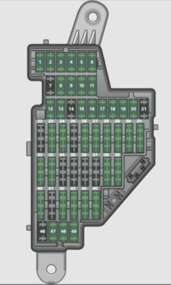
Instrument panel
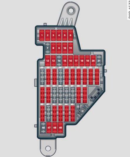
| Number | Equipment | Ampere rating [A] |
| 1 | Manua l head light beam adjustment, automat ic headlight beam adjustment, AFS 1 control module, engine components, light switch (switch lighting/illumination), diagnosis socket |
10 |
| 2 | Automatic transmission, control module for CAN data transfer (gateway), electromechanical steering, shift gate automatic transmission, fuel tank control unit, engine control unit, brakes control (ABS), Electronic Stabili zation Program (ESP), Anti-Slip Regulation (ASR) | 10 |
| 3 | Airbag | 5 |
| 4 | Air-conditioning (pressure sensor, air quality sensor), button for Electronic Stabilization Program (ESP), AntiSlip Regulat ion (ASR), tire pressure monitor display, oil level senso r, back-up light switch, front se at heating, parking a id, seat-occupancy recognition (on USA vehi cles), garage door opener, automatic mirror dimming, headlight assistant, heated windshield washer nozzles, air conditioning (control module) | 5 |
| 5 | AFS headlights (left side) | 5 |
| 6 | AFS headlights (right side) | 5 |
| 7 | — | — |
| 8 | Instr ument cluster | 5 |
| 9 | Navigation system, radio system | 15 |
| 10 | Digital radio, cell phone, TV equipment | 7,5 |
| 11 | Automatic mirror dimming, headlight assistant | 10 |
| 12 | Central locking (front doors) | 10 |
| 13 | Central locking (rear doors) | 10 |
| 14 | Electronic Stabilizati on Program (ESP) (control module), shift gate automatic transmission | 10 |
| 15 | Interior lights, reading lights | 10 |
| 16 | Diagnostic connector, rain sensor, air conditioning (control module), tire pressure monitor display (control module) | 10 |
| 17 | Anti -theft alarm warning system | 5 |
| 18 | Diagnose Starter | 5 |
| 19 | All Wheel Drive | 10 |
| 20 | Audi magnetic ride | 10 |
| 21 | — | — |
| 22 | Blower fan | 40 |
| 23 | Driver’s side power window, front | 30 |
| 24 | Power outlet front | 20 |
| 25 | Rear window defogger | 30 |
| 26 | Power outlet in luggage compartment | 20 |
| 27 | Fuel tank control module, fuel pump | 15 |
| 28 | Power window , rear | 30 |
| 29 | — | — |
| 30 | — | — |
| 31 | — | — |
| 32 | — | — |
| 33 | Sliding/pop-up roof | 20 |
| 34 | — | — |
| 35 | — | — |
| 36 | Lumbar support | 10 |
| 37 | Heated seats, front | 20 |
| 38 | Passenger side power window, front | 30 |
| 39 | Special function interface | 5 |
| 40 | Starter | 40 |
| 41 | Rear window wiper | 15 |
| 42 | — | — |
| 43 | Body control module | 20 |
| 44 | — | — |
| 45 | — | — |
| 46 | — | — |
| 47 | Cell phone package (VDA interface) | 5 |
| 48 | — | — |
| 49 | — | — |
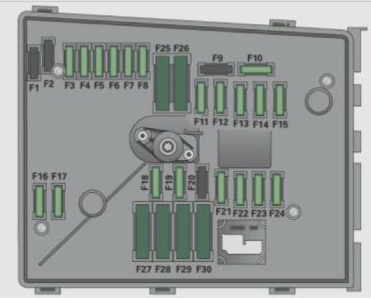
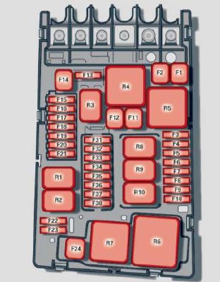
Engine compartment
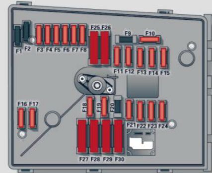
| Number | Equipment | Ampere rating [A] |
| F1 | — | — |
| F2 | Engine components | 20 |
| F3 | Battery voltage | 5 |
| F4 | ESP valves, Anti -lock brake system (ABS) valves | 20 |
| 30 | ||
| F5 | Transmission control module | 15 |
| F6 | Steering wheel electronics | 5 |
| F7 | — | — |
| F8 | — | — |
| F9 | — | — |
| F10 | Engine control module, main relay | 5 |
| 10 | ||
| F11 | — | — |
| F12 | Control module for CAN data transfer (gateway) | 5 |
| F13 | Engine control module (diesel engine/gasoline engine) | 15 |
| 20 | ||
| 25 | ||
| 30 | ||
| F14 | Ignition coils, engine components (diesel engine) | 20 |
| F15 | Preheating control module/engine component, tank diagnosis, oxygen sensor | 10 |
| 15 | ||
| F16 | Body control module (right) | 30 |
| F17 | Horn | 15 |
| F18 | Audio amplifier | 30 |
| F19 | Front windshield wiper system | 30 |
| F20 | Water return -flow pump, volume regulator valve | 10 |
| 15 | ||
| 20 | ||
| F21 | Oxygen sensor (diesel engine/gasoline engine)/vacuum pump | 10 |
| 15 | ||
| 20 | ||
| F22 | Clutch pedal switch, brake light switch | 5 |
| F23 | Engine relay, water pump/ engine components/volume regulator valve | 5 |
| 10 | ||
| 15 | ||
| F24 | Engine components, water pump | 10 |
| F25 | Pump (ESP/ABS), ABS valve | 40 |
| F26 | Body control module (left) | 30 |
| F27 | Secondary air pump, preheating control module | 40 |
| F28 | — | — |
| F29 | Fuse assignment in the left-side instrument panel (special equipment) | 50 |
| F30 | Power supply relay terminal 15 | 50 |
WARNING: Terminal and harness assignments for individual connectors will vary depending on vehicle equipment level, model, and market.