Honda Accord (1997 – 2002) – fuse box diagram
Year of production: 1997, 1998, 1999, 2000, 2001, 2002
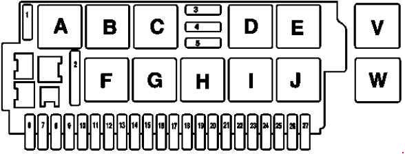
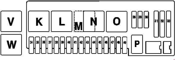
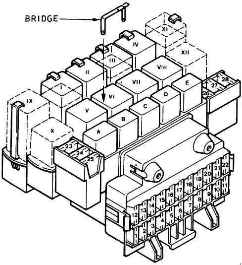
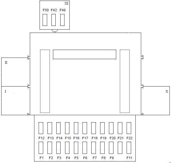
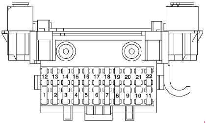
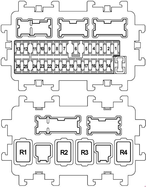
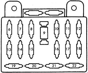
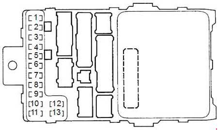
Driver’s Under-Dash Fuse box
Front View
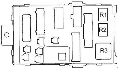
Rear View
| Number | Fuse name | A | Circuits Protected |
| 1 | FUEL PUMP | 15 | PGM-FI main relay, SRS unit (VA) |
| 2 | SRS | 10 | SRS unit (VB) |
| 3 | HEATER CONTROL A/С CLUTCH RELAY COOLING FAN RELAY |
7,5 | A/C compressor controls, Air delivery, Blower controls, Fans, Rear window defogger relay, Seat heaters (Canada EX) |
| 4 | R/C MIRROR | 7,5 | ABS control unit (All except ’01-’02 V6), ABS/TCS control unit (’01-’02 V6), Power mirrors, Power mirror defoggers (Canada), Option connector S |
| 5 | DAY LIGHT | 7,5 | DRL control unit (Canada) |
| 6 | ECU CRUISE CONTROL |
15 | Charging system, Cruise control, Engine mount control system, Evaporative emission control system, Fuel and emissions, Gauge assembly, Radiator fan control module (V6), VSS (M/T) |
| 7 | FR WASHER SUN ROOF RELAY SIDE SRS SRS |
7,5 | Wiper/washer, SRS (with side SRS) |
| 8 | ACC RELAY | 7,5 | Accessory power socket relay, Option connector R |
| 9 | BACK UP LIGHT INSTRUMENT LIGHT |
7,5 | Back-up lights, Brake light failure sensor, Clock, Driver’s and passenger’s multiplex control units, DRL indicator (Canada), Gauge assembly, Security system (USA except EX), Shift lock solenoid (A/T) |
| 10 | TURN LIGHTS | 7,5 | Turn signal/hazard relay |
| 11 | IG COIL | 7,5 | Ignition coil (L4) |
| 12 | FR WIPER | 30 | Wiper/washer |
| 13 | STARTER SIGNAL | 7,5 | PCM or ECM, PGM-FI main relay, Starter |
| Relay | |||
| R1 | Starter cut relay | ||
| R2 | Reverse relay | ||
| R3 | Turn signal/hazard relay | ||
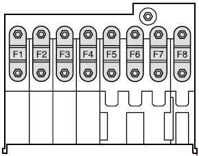
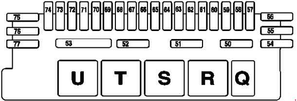
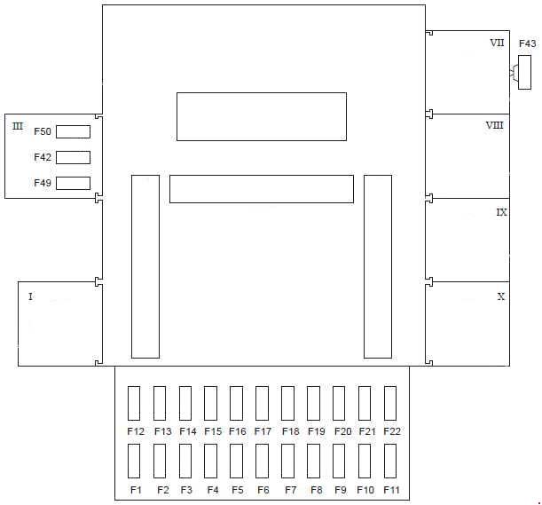
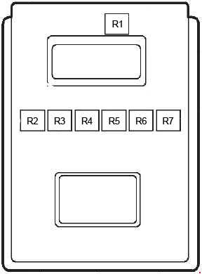
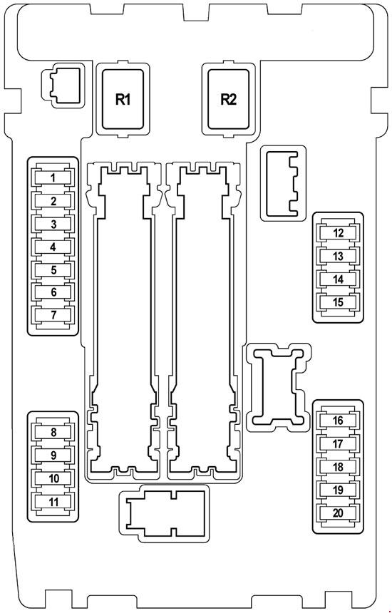
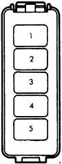
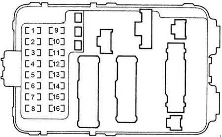
Passenger’s Under-Dash Fuse Box
Front View
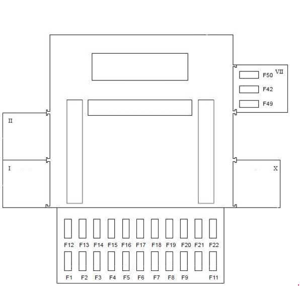
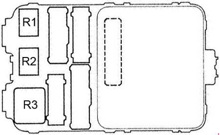
Rear View
| Number | Fuse name | A | Circuits Protected |
| 1 | SUN ROOF MOTOR | 30 | Moon roof |
| 2 | POWER SEAT REC | 20 | Power seat up-down motor (2-way adjustable), Power seat rear up-down and recline motors (8-way adjustable) |
| 3 | POWER SEAT SLIDE | 20 | Power seat slide motor (4-way adjustable) |
| 4 | POWER SEAT SLIDE | 20 | Power seat front up-down and slide motors (8-way adjustable) |
| 5 | POWER SEAT REC | 20 | Power seat recline motor (4-way adjustable) |
| 6 | DAY LIGHT | 10 | DRL control unit (Canada) |
| LAF HEATER | 20 | Primary H02S relay (ULEV) | |
| 7 | P/W REAR L SUNROOF RELAY |
20 | Left rear window motor, Moonroof open and close relays |
| 8 | P/W FRONT R | 20 | Front passenger’s window motor |
| 9 | RADIO CIGARETTE LIGHTER |
20 | Accessory power socket, Audio unit |
| 10 | SMALL LIGHT LICENSE LIGHT |
10 | Dash and console lights, Driver’s multiplex control unit, Front parking lights, Front side marker lights, Glove box light, Ucense plate light, TaiNights, Vanity mirror lights |
| 11 | INTERIOR LIGHT COURTESY LIGHT |
7,5 | Ceiling light, Door courtesy lights, Spotlights, Trunk light |
| 12 | POWER DOOR LOCK | 20 | Passenger’s multiplex control unit |
| 13 | CLOCK BACK UP | 7,5 | Climate control unit (w/auto A/С), Clock, Door multiplex control unit, Driver’s multiplex control unit, Gauge assembly, Heater control panel (w/manual A/С), Passenger’s multiplex control unit, PCM or ECM, Security indicator (EX) |
| 14 | ABS MTR CHK | 7,5 | ABS control unit (All except ’01-’02 V6) |
| 7,5 | ABS/TCS control unit (’01-’02 V6) | ||
| 15 | P/W FRONT L | 20 | Door multiplex control unit |
| 16 | P/W REAR R | 20 | Right rear window motor |
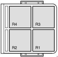
| Relay | |||
| R1 | Power window relay | ||
| R2 | Accessory power socket relay | ||
| R3 | Rear window defogger relay | ||
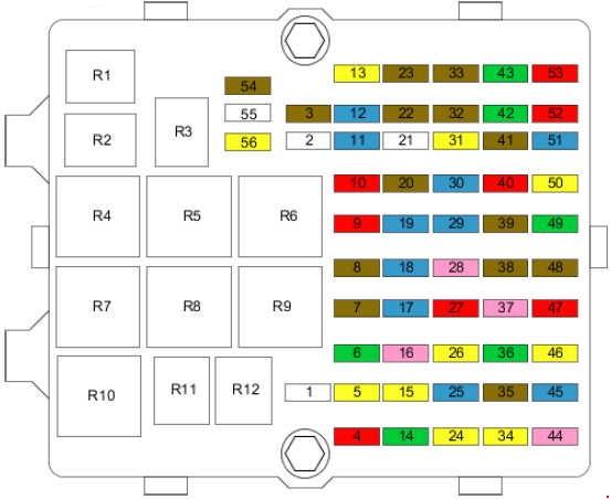
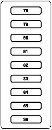
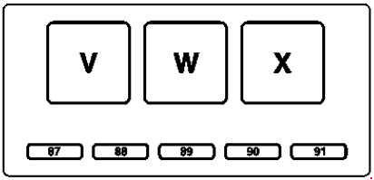
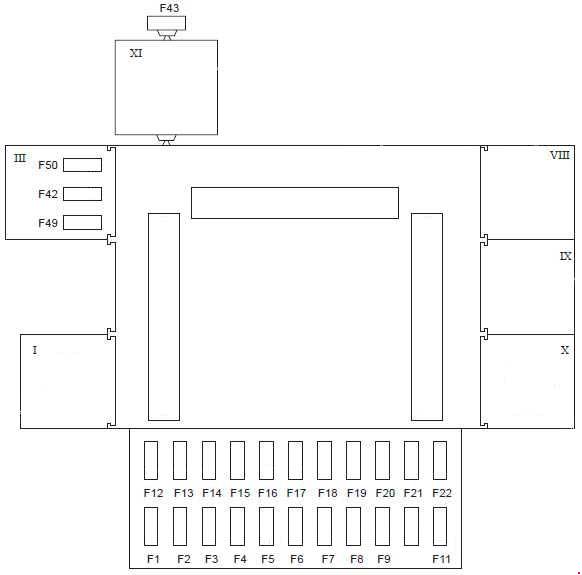
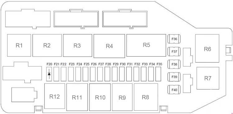
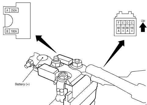
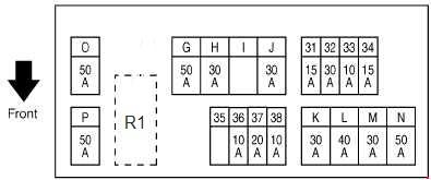
Under-Hood Fuse Box
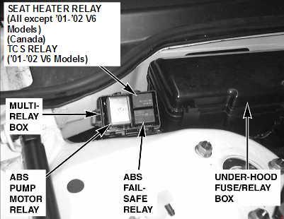
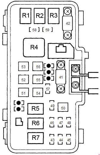
| Number | Fuse name | A | Circuits Protected |
| 41 | BATTERY | 100 | Power distribution |
| 42 | IG1 MAIN | 50 | Ignition switch (BAT) |
| 43 | RIGHT HEAD LIGHT | 20 | DRL control unit (Canada), Right headlight |
| 44 | — | — | — |
| 45 | LEFT HEAD LIGHT | 20 | DRL control unit (Canada), High beam cut relay (Canada), High beam indicator (USA), Left headlight |
| 46 | ACG S | 15 | DLC, PGM-FI main relay |
| 47 | STOP | 20 | ABS control unit, Brake lights, Cruise control unit, Horn relay, Ignition key light, Key interlock switch (AIT), PCM or ECM |
| 48 | ABS F/S | 20 | ABS control unit (All except ’01-02 V6), ABS/TCS control unit (’01-02 V6) |
| 49 | HAZARD | 15 | Turn signal/hazard relay |
| 50 | ABS MOTOR | 30 | ABS pump motor, Fuse 14 (in passenger’s under-dash fuse/relay box) |
| 51 | POWER WINDOW MOTOR | 40 | Fuse 1 (in passenger’s under-dash fuse/relay box), Power window relay |
| 52 | BSC F/S | 20 | TCS relay |
| 53 | RR DEFROSTER | 40 | Rear window defogger |
| 54 | BACK UP, ACC | 40 | Fuses 9, 10,11,12, and 13 (in passenger’s under-dash fuse/relay box) |
| 55 | POWER SEAT | 40 | Fuses 2, 3, 4, 5, and 6 (in passenger’s under-dash fuse/relay box) |
| 56 | HEATER MOTOR | 40 | Blower motor |
| 57 | COOLING FAN | 20 | Radiator fan motor |
| 58 | CONDENSER FAN | 20 | A/C compressor clutch, Condenser fan motor, Radiator fan control module (V6) |
| 59 | HEATED SEAT | 20 | Seat heaters (Canada EX) |
| Relay | |||
| R1 | Condenser fan relay | ||
| R2 | Radiator fan relay | ||
| R3 | A/C compressor clutch relay | ||
| R4 | Blower motor relay | ||
| R5 | Horn relay | ||
| R6 | Headlight relay 2 | ||
| R7 | Headlight relay 1 | ||
WARNING: Terminal and harness assignments for individual connectors will vary depending on vehicle equipment level, model, and market.