Jaguar X-Type (2001 – 2003)- fuse box diagram

Jaguar X-Type (2001 – 2003)- fuse box diagram

Year of production: 2001, 2002, 2003

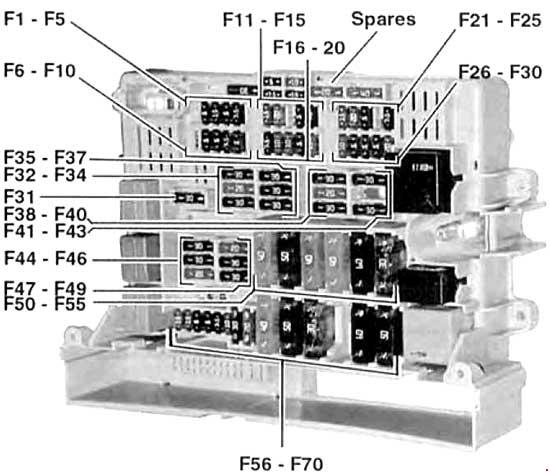
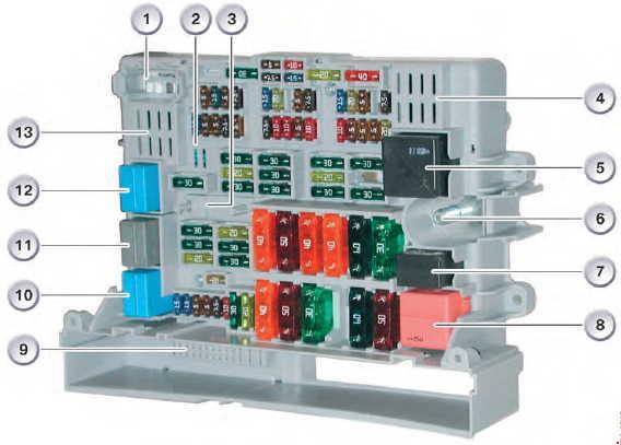
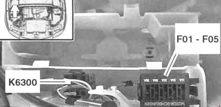
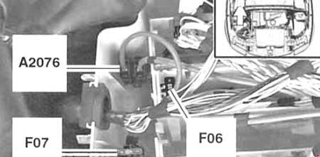
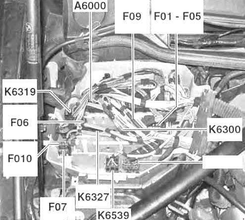
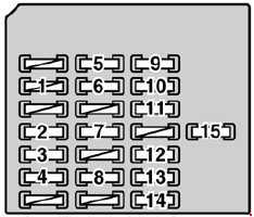
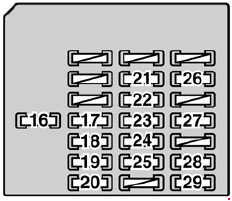
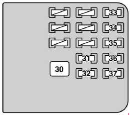
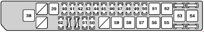
Engine compartment fuse box
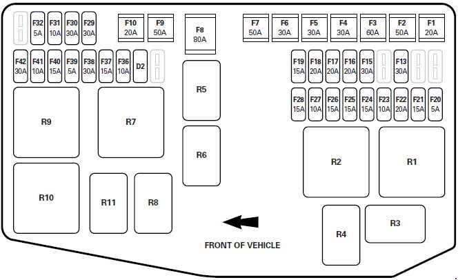
Jaguar X-Type - fuse box diagram - engine compartment
Jaguar X-Type – fuse box diagram – engine compartment
Number Ampere ratting [A] Protected circuit
F1 20 Dip beam, High Intensity Discharge(HID) light relay
F2 50 Ignition relay feed
F3 60 ABS
F4 30 Rear window heater relay, heated mirrors
F5 30 Auxiliary vacuum pump, transmission control module
F6 30 Heater blower relay
F7 50 Power supply to passenger compartment fuse box
F8 80 Fan module
F9 50 Engine management system power relay, headlight power wash
F10 20 Headlight power wash relay
F11
F12
F13 30 Heated front screen right-hand side
F14
F15 30 Heated front screen left-hand side
F16 20 Left-hand dip beam, day time running lights (DTRL), autolights
F17 20 Right-hand dip beam, HID lights
F18 20 Throttle motor supply (2.5L and 3.0L), fuel pump (2.0L)
F19 15 2002-2003: Screenwash pump, rain sensing system
F20 5 Navigation display
F21 15 Side (Parking) lights
F22 20 Accessory relay
F23 10 Air conditioning compressor clutch relay
F24 15 Door lock power
F25 15 Direction indicators (GEM)
F26 15 Horns relay
F27 10 Transmission control module, transit relay
F28 30 2001-2002: Ignition switch
15 2002-2003: Ignition switch
F29 30 Starter motor
F30 30 Accessory sockets
F31 10 Engine management relay coil
F32 5 Engine management control
F33 20 2001: Throttle motor relay
F34
F35 Diode EMS relay
F36 10 Canister purge valve, canister close valve, airflow meter, throttle motor relay, power wash relay coil, air conditioning relay coil, cruise control module
F37 15 Engine management system, fan speed controller, speed controller
F38 30 Oxygen sensor heaters
F39 5 Variable intake valves
F40 15 2002-2003: Automatic transmission control module
F41 10 Injectors
F42 30 Oxygen sensor heaters B
Relay
R1 40 Windscreen wipers
R2 70 Heated front windscreen
R3 20 Horn
R4 20 Accessories
R5 20 Headlight powerwash
R6 20 Air conditioning compressor clutch
R7 70 Engine management system
R8 20 Transmission control module
R9 40 Dip beam/HID
R10 40 Starter motor
R11 20 Throttle motor (2.5/3.0L), fuel pump (2.0L)

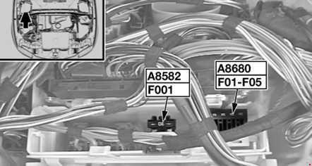
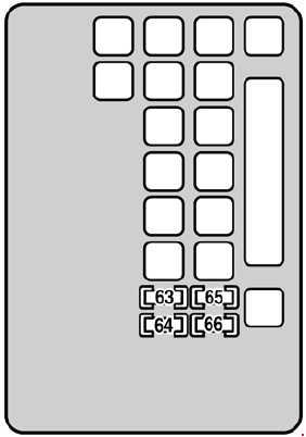
Passenger compartment fuse box
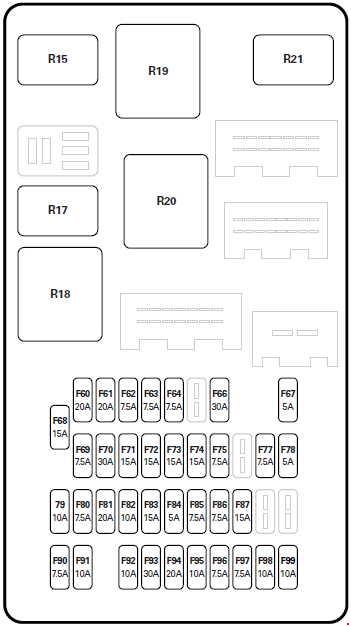
Jaguar X-Type - fuse box diagram - passenger compartment
Jaguar X-Type – fuse box diagram – passenger compartment
Number Ampere ratting [A] Protected circuit
F60 20 Power windows left-hand
F61 20 Power windows right-hand
F62 10 2001: Rear fog lights
7,5 2002-2003: Rear fog lights
F63 10 2001: Right-hand- front side light, side markers, rear tail lights
7,5 2002-2003: Right-hand- front side light, side markers, rear tail lights
F64 10 2001: Left-hand – front side light, side markers, rear tail lights
7,5 2002-2003: Left-hand – front side light, side markers, rear tail lights
F65
F66 30 Left-hand power seat switches, heater module, lumbar pump (2002-2003)
F67 5 Battery back-up sounder, transit relay, HID/dip relay, auxiliary vacuum pump control, automatic transmission control module (2002-2003)
F68 15 Cigar lighter
F69 10 Telematics display (2002-2003), In-car entertainment head unit, antenna module, navigation module, VICS (Japan), tuner (2001), voice module (2001-2002), parking aid, amplifier premium 1 system, phone handset, phone power supply module, instrument cluster, PATS module.
F70 30 Right-hand power seat switches, heater module, lumbar pump (2002-2003)
F71 15 VICS (Japan), voice module, telephone transceiver, telephone handset
F72 15 Radio head unit, CD player, navigation electronic control module, Jaguardiagnosticconnector/OBD2 connector
F73 15 Sunroof unit/module
F74 15 Instrument cluster, Premium ICE amplifier unit
F75 10 2001: Mirror fold-back module, battery back-up sounder, air conditioning ECU
7,5 2002-2003: Mirror fold-back module, battery back-up sounder, air conditioning EC
F76
F77 10 2001: Screenwash pump, rain sense
7,5 2002-2003: Left-hand and right-hand heated seats modules
F78 5 Phone power supply, Jaguar Telematics (2001-2002)
F79 10 Reverse lights, reverse light switch, reverse park aid, electrochromic mirror, instrument cluster
F80 10 2001: Park interlock, heater switch, OBD2, blower relay
7,5 2002-2003: Park interlock, heater switch, OBD2, blower relay
F81 20 Fuel pump control module (2.5/3.0L), fuel pump relay (2.0L)
F82 20 2001: Manual transmission reverse lights, variable power steering, alternator, TCM
10 2002-2003: Variable power steering, alternator. Manual transmission only: (Reverse lights, reverse light switch reverse park aid, electrochromic mirror, instrument cluster)
F83 10 2001: Left-hand and right-hand heated seats modules
F84 5 Instrument cluster, passenger airbag fascia light, seat weight sensor
F85 10 2001: Right-hand high beam light
7,5 2002-2003: Right-hand high beam light
F86 10 2001: Left-hand high beam light
7,5 2002-2003: Left-hand high beam light
F87 15 Front fog lights, master light switch
F88
F89
F90 15 2001: Stop lights, cruise control
7,5 2002-2003: Stop lights, cruise control
F91 10 Sunroof, electrochromic mirror, power windows, power mirrors (2002-2003)
F92 10 Manual transmission cruise control switch, ignition coils, automatic transmission rotary switch
F93 30 Windscreen wipers
F94 20 HID module
F95 10 Airbag restraints module
F96 10 2001: ABS module
7,5 2002-2003: ABS module
F97 10 2001: Glove compartment light, instrument cluster lights, licence plate lights
7,5 2002-2003: Glove compartment light, instrument cluster lights, licence plate lights
F98 10 Mirror heaters
F99 10 Luggage compartment light, footwell lights, puddle lights, vanity mirror lights, interior lights, aircon control unit, roof console unit.
Relay
R15 20 High beam/front fog lights relay
R16 20
R17 20 Reverse lights
R18 70 Ignition relay
R19 40 Heated rear window relay
R20 40 Blower relay
R21 20 Battery saver relay

WARNING: Terminal and harness assignments for individual connectors will vary depending on vehicle equipment level, model, and market.

New Holland TL70, TL80, TL90, TL100 – fuse box diagram

New Holland TL70, TL80, TL90, TL100 – fuse box diagram

Year of production:

Without a Cab

New Holland TL70, TL80, TL90, TL100 - fuse box diagram - without CAB
New Holland TL70, TL80, TL90, TL100 – fuse box diagram – without CAB

With a Cab

New Holland TL70, TL80, TL90, TL100 - fuse box diagram - with CAB
New Holland TL70, TL80, TL90, TL100 – fuse box diagram – with CAB
Number Ampere ratting [A] Protected circuit
1 10 With Power Shuttle: Power Shuttle circuit, (+ key)
2 5 Without Power Shuttle: 2 Speed Power Shift circuit
With Power Shuttle: Power Shuttle circuit, (+ key)
3 5 Front right-hand and rear left-hand side lights
4 5 Front left-hand and rear left-hand side lights, controls and instruments lighting
5 15 Without a Cab: Grille front work lights
With a Cab: Lower front work lights
6 15 With a Cab: Rear work lights
7 15 Full beam headlights
8 15 Dipped beam headlights
9 5 Without a Cab with Power Shuttle: Power Shuttle circuit, (+ battery)
With a Cab: Electronic lift circuit
With a Cab with Power Shuttle: Electronic lift circuit and Power Shuttle, (+ battery)
10 15 Without a Cab: Hazard Lights
25 With a Cab: Direction indicators and hazard lights
11 15 Horn, power socket, buzzer (with Power Shuttle), cigar lighter (with cab), rotating beacon (with cab), overhead lighting (with a Cab with Power Shuttle), radio (with a Cab with Power Shuttle)
beacon.
12 10 + instruments, seat safety circuit, trailer brake
13 5 Engine cut-out electromagnets
14 5 With a Cab: Electronic lift circuit, (+ key)
15 10 Without a Cab: Rear work light
With a Cab: Rear and windscreen wipers, windscreen and rear window wiper pump
16 5 Sediment filter circuit, air conditioning compressor circuit (with cab)
17 10 4WD circuit, differential lock, brake light (with cab)
18 5 Rear power take-off circuit
19 15 With a Cab: Upper front work lights
20 10 Without a Cab: Direction indicators
5 With a Cab: Digital instrument circuit
21 10 Brake lights, seat (with cab)
22 25 With a Cab: Fan unit, radio
23 5 Starter safety circuit
24 15 Thermostart
Relay
I 70A engine start-up relay
II Electrohydraulic 4WD. relay circuit
III Full beam headlights relay
IV Reserve
V Dipped beam headlights relay
VI With a Cab: Side/tail lights circuit relay
Without a Cab: Electronic flashing light
VII Differential lock and brake lights circuit relay
VIII With a Cab: Front/upper work lights relay
IX 2 Speed Power Shift circuit relay
X Differential lock circuit relay
XI With a Cab: Front/lower work lights circuit relay
XII With a Cab: Rear work lights circuit relay
A
B With a Cab: Conditioner circuit relay
C Differential lock circuit relay
D Brake lights circuit relay
E Trailer brake circuit relay
F Electrohydraulic PTO circuit relay
G Electrohydraulic PTO circuit relay
H Trailer brake circuit relay
New Holland TL70, TL80, TL90, TL100 - fuse box diagram
New Holland TL70, TL80, TL90, TL100 – fuse box diagram
Number Ampere ratting [A] Protected circuit
1 40 40A power socket.
2 40 Fuses 3, 4, 7, 8, 9, 10, 11
3 50 Fuses 1, 2, 12, 13, 14, 15, 16, 17, 18, 20, 21, 22, 23, 24 and starter circuit
4 50 With a Cab: Fuses 5, 6, 19, 25, 26 (Work lights)

WARNING: Terminal and harness assignments for individual connectors will vary depending on vehicle equipment level, model, and market.

BMW 1 (E81/E82/E87/E88; 2004 – 2013) – fuse box diagram

BMW 1 (E81/E82/E87/E88; 2004 – 2013) – fuse box diagram

Year of production: 2004, 2005, 2006, 2007, 2008, 2009, 2010, 2011, 2013

Fuse box

BMW 1 - fuse box diagram
BMW 1 – fuse box diagram
Number Ampere ratting [A] Protected circuit
F1 15 up to 09.2005: Transmission control
10 as of 09.2006: Rollover protection controller
F2 5 up to 03.2007: Electrochromic interior rear view mirror
as of 03.2007:
Instrument cluster control unit
OBDII socket
F3
F4 5 Car access system
F5 7,5 up to 03.2007: Function control centre, roof
20 as of 03.2007: Electric fuel pump
F6 15 up to 09.2007: Transmission control module
5 as of 09.2007:
AUC sensor
DC/DC converter
F7 20 up to 03.2007: Control unit, independent/auxiliary  heating
F8 5 up to 03.2007: CD changer
20 as of 03.2007: Amplifier
F9 10 up to 03.2007: Active cruise control
F10
F11 10 up to 09.2007: Radio
30 as of 09.2007:
N52 (125i, 130i):
Oil condition sensor
DISA actuator 1
DISA actuator 2
Fuel tank vent valve
Crankshaft sensor
Air mass flow sensor
20 as of 09.2007:
N46/TU2 (118i, 120i), N45/TU2 (116i):
Fuel injector, cylinder 1
Fuel injector, cylinder 2
Fuel injector, cylinder 3
Fuel injector, cylinder 4
N43 (116i, 118i, 120i):
Oxygen sensor before catalytic converter
Oxygen sensor 2 before catalytic converter
Oxygen sensor after catalytic converter
F12 20 up to 09.2007: Function control centre, roof
15 as of 09.2007: Relay, electric vacuum pump
F13 5 Controller
F14
F15 5 AUC sensor
F16 15 up to 03.2007: Right horn
03.2007-09.2007:
Left horn
Right horn
10 as of 09.2007:
N46/TU2 (118i, 120i), N45/TU2 (116i):
E-box fan
Crankshaft sensor
Fuel tank vent valve
Hot-film air mass meter
N43 (116i, 118i, 120i):
E-box fan
Crankshaft sensor
Variable intake system: Position sensor and actuator
Air mass flow sensor
Radiator shutter drive unit
N52 (125i, 130i):
EAC sensor
Secondary air pump relay
E-box fan
F17 5 up to 03.2007: Navigation system
10 as of 09.2007:
N52 (125i, 130i):
Exhaust flap
USA: Diagnostic module for fuel tank leakage
N43 (116i, 118i, 120i):
Nitrogen oxide sensor
F18 5 up to 03.2007: CD changer
as of 03.2007: Electrochromic interior rear view mirror
F19 7,5 up to 03.2007:
Comfort access control module
Outer door handle electronic module, driver’s side
Outer door handle electronic module, passenger’s side
Siren and tilt alarm sensor
as of 03.2007: Siren and tilt alarm sensor
F20 5 Dynamic stability control (DSC)
F21 7,5 Driver door switch cluster
Outside rear view mirrors
F22
F23 10 without USA:
Digital tuner
Video module
USA:
Satellite receiver
Digital tuner US
F24 5 Tire pressure control (RDC)
F25
F26 10 Telematic control unit (TCU)
Universal charging and hands-free facility (ULF)
Telephone transceiver (without TCU or ULF)
Aerial splitter
Compensator
Eject box
F27 5 Driver door switch cluster
Telephone transceiver
F28 5 Function control centre, roof
Park distance control (PDC)
F29 5 AUC sensor (up to 03.2007)
Driver’s seat heating module
Passenger’s seat heating module
F30 20 Front cigar lighter
Charging socket, centre console, rear
Luggage compartment socket outlet
F31 30 up to 09.2005: Dynamic stability control (DSC)
20 as of 09.2005:
Radio (with RAD Radio or RAD2-BO User interface)
CCC/M-ASK (with M-ASK-BO User interface or CCC-BO User interface)
F32 30 up to 03.2007:
Seat module, front left (with memory)
Driver’s seat heating module (without memory)
as of 03.2007: Seat module, front left
F33 30 up to 03.2007:
Switch, passenger’s seat adjustment
Switch for passenger’s seat backrest width adjustment
Passenger’s lumbar support switch
Valve block for passenger’s seat backrest width adjustment
Valve block, front right lumbar support
5 as of 03.2007:
Comfort access control unit
Outer door handle electronic module, driver’s side
Outer door handle electronic module, passenger’s side
F34 30 up to 03.2007: Amplifier
5 as of 03.2007: CD changer
F35 20 up to 09.2005:
N46 (118i, 120i), N45 (116i):
Electric fuel pump
N52 (125i, 130i), M47/TU2 (118d, 120d):
Fuel pump control  (EKPS)
30 as of 09.2005: Dynamic stability  control (DSC)
F36 30 Footwell module
F37 30 up to 03.2007:
Switch for driver’s seat backrest width adjustment
Driver’s lumbar support switch
Valve block for driver’s seat backrest width adjustment
Valve block, front left lumbar support
10 03.2007-09.2007:
Switch for passenger’s seat backrest width adjustment
Switch for driver’s seat backrest width adjustment
Passenger’s lumbar support switch
Driver’s lumbar support switch
Valve block for driver’s seat backrest width adjustment
Valve block, front left lumbar support
30 as of 09.2007:
N52 (125i, 130i):
DME control unit
Electric coolant pump
Thermostat, characteristic map cooling
Intake camshaft sensor
Exhaust camshaft sensor
VANOS solenoid valve, intake
VANOS solenoid valve, exhaust
F38 30 as of 09.2007:
N52 (125i, 130i):
Oxygen sensor before catalytic converter
Oxygen sensor 2 before catalytic converter
Oxygen sensor after catalytic converter
Oxygen sensor 2 after catalytic converter
Crankshaft breather heating 1
F39 30 up to 09.2007: Wiper motor
as of 09.2007:
N52 (125i, 130i):
Fuel injector, cylinder 1
Fuel injector, cylinder 2
Fuel injector, cylinder 3
Fuel injector, cylinder 4
Fuel injector, cylinder 5
Fuel injector, cylinder 6
Ignition coil, cylinder 1
Ignition coil, cylinder 2
Ignition coil, cylinder 3
Ignition coil, cylinder 4
Ignition coil, cylinder 5
Ignition coil, cylinder 6
Interference suppression capacitor for ignition coils
F40 20 up to 09.2005:
Radio (with RAD Radio or RAD2-BO User interface)
CCC/M-ASK (with M-ASK-BO User interface or CCC-BO User interface)
as of 09.2005-03.2007:
Electric fuel pump (without EKPS)
Fuel pump control (EKPS)
7,5 as of 03.2007: Function control centre, roof
F41 30 Footwell module
F42 30 up to 09.2005:
Switch for driver’s seat backrest width adjustment
Driver’s lumbar support switch
Valve block for driver’s seat backrest width adjustment
Valve block, front left lumbar support
09.2006-03.2007: Trailer module
40 as of 03.2007: Footwell module
F43 30 Headlight washer pump
F44 30 Trailer module
F45 20 up to 09.2005: Trailer socket
40 09.2005-03.2007: Active steering
30 as of 03.2007: Seat module, front right
F46 30 Lockout circuit for rear window defogger (positive)
F47 20 as of 09.2005: Trailer socket
F48 20 Intermittent wipe/wash control unit, rear
F49 30 up to 03.2007: Passenger’s seat heating module
03.2007-09.2007: Seat module, front right
40 as of 09.2007: Active steering
F50 40 up to 09.2005: Active steering
10 as of 03.2007: DME control unit
F51 50 Car access system
F52 50 up to 03.2007: Footwell module
20 as of 03.2007: Driver’s seat heating module
F53 50 up to 03.2007: Footwell module
20 as of 03.2007: Passenger’s seat heating module
F54 60 up to 03.2007: B+ potential distributor
30 as of 03.2007: Trailer module
F55
F56 15 Central locking
F57 15 Central locking
F58 5 Instrument cluster
OBD II socket
F59 5 Steering column switch cluster
F60 7,5 Heating/air conditioning system
F61 10 Central information display
Glove compartment light
Luggage compartment light, right
F62 30 Window control
F63 30 Window control
F64 30 Window control
F65 40 Dynamic stability control (DSC)
F66 50 Fuel heater
F67 50 up to 03.2007: Blower output stage
30 as of 03.2007: Blower output stage
F68 50 up to 03.2007: Relay, electric vacuum pump
40 as of 03.2007: Footwell module
F69 50 Electric fan
F70 50 Secondary air injection pump
N45 (116i):
Electric vacuum pump
F71 20 Trailer socket
F72 15 N45, N45/TU2 (116i):
Relay, electric vacuum pump
F73 10 N46/TU2 (118i, 120i), N45/TU2 (116i):
Crankshaft sensor
E-box fan
Fuel tank vent valve
Hot-film air mass meter
03.2007-09.2007:
N52 (125i, 130i):
EAC sensor
Secondary air pump relay
E-box fan
Hot-film air mass meter
F74 10 03.2007-09.2007:
N52 (125i, 130i):
Exhaust flap
      USA: Diagnostic module for fuel tank leakage
as of 09.2007:
N43 (116i, 118i, 120i):
Nitrogen oxide sensor
F75
F76 20 03.2007-09.2007:
N43 (116i, 118i, 120i):
Oxygen sensor before catalytic converter
Oxygen sensor 2 before catalytic converter
Oxygen sensor after catalytic converter
   N46/TU2 (118i, 120i), N45/TU2 (116i):
Fuel injector, cylinder 1
Fuel injector, cylinder 2
Fuel injector, cylinder 3
Fuel injector, cylinder 4
30 03.2007-09.2007:
N52 (125i, 130i):
Oil condition sensor
DISA actuator 1
DISA actuator 2
Fuel tank vent valve
Crankshaft sensor
Air mass flow sensor
F77 30 N43 (116i, 118i, 120i):
DME control unit
Oil pressure control valve
Intake camshaft sensor
Exhaust camshaft sensor
VANOS solenoid valve, intake
VANOS solenoid valve, exhaust
N45/TU2 (116i):
DME control unit
Suction jet pump valve
Intake camshaft sensor
Exhaust camshaft sensor
VANOS solenoid valve, intake
VANOS solenoid valve, exhaust
Heating, crankcase breather
N46/TU2 (118i, 120i):
DME control unit
Characteristic map thermostat
Intake camshaft sensor
Exhaust camshaft sensor
VANOS solenoid valve, intake
VANOS solenoid valve, exhaust
Heating, crankcase breather
03.2007-09.2007:
N52 (125i, 130i):
Fuel injector, cylinder 1
Fuel injector, cylinder 2
Fuel injector, cylinder 3
Fuel injector, cylinder 4
Fuel injector, cylinder 5
Fuel injector, cylinder 6
Ignition coil, cylinder 1
Ignition coil, cylinder 2
Ignition coil, cylinder 3
Ignition coil, cylinder 4
Ignition coil, cylinder 5
Ignition coil, cylinder 6
Interference suppression capacitor for ignition coils
F78 30 N43 (116i, 118i, 120i):
Ignition coil, cylinder 2
Ignition coil, cylinder 3
Ignition coil, cylinder 4
Interference suppression capacitor for ignition coils
N46/TU2 (118i, 120i), N45/TU2 (116i):
Oxygen sensor before catalytic converter
Oxygen sensor 2 before catalytic converter
Oxygen sensor after catalytic converter
03.2007-09.2007:
N52 (125i, 130i):
DME control unit
Electric coolant pump
Thermostat, characteristic map cooling
Intake camshaft sensor
Exhaust camshaft sensor
VANOS solenoid valve, intake
VANOS solenoid valve, exhaust
F79 30 03.2007-09.2007:
   N43 (116i, 118i, 120i):
Oil condition sensor
Heating, crankcase breather
Electrical changeover valve, engine mount
Fuel tank vent valve
Volume control valve
Characteristic map thermostat
N46/TU2 (118i, 120i), N45/TU2 (116i):
Ignition coil, cylinder 1
Ignition coil, cylinder 2
Ignition coil, cylinder 3
Ignition coil, cylinder 4
N52 (125i, 130i):
Oxygen sensor before catalytic converter
Oxygen sensor 2 before catalytic converter
Oxygen sensor after catalytic converter
Oxygen sensor 2 after catalytic converter
Crankshaft breather heating 1
F80
F81 30 Trailer module
F82
F83
F84 30 Headlight washer pump
F85
F86
F87
F88 20 up to 09.2007: Fuel pump control (EKPS)
30 as of 09.2007: Blower output stage
BMW 1 - fuse box diagram
BMW 1 – fuse box diagram
Number Explanation
1 Wiring harness connector
2 Double relay for electric fuel pump/fanfare horn (M47TU2 fanfare horn only) is mounted on the PCB in the housing
3 Term. 30g_f relay (only installed in connection with corresponding equipment) is mounted on the PCB in the housing
4 Term. 15 relay is mounted on the PCB in the housing
5 Term. 30g relay
6 Power supply
7 Relay for windscreen washer system
8 Relay for secondary air pump
9 Internal interface, junction box control unit
10 Relay for rear window wiper
11 Relay for heated rear window
12 Relay for wiper stage 1
13 Relay for wiper stage 2 is mounted on the PCB in the housing
BMW 1 - fuse box diagram
BMW 1 – fuse box diagram
BMW 1 - fuse box diagram
BMW 1 – fuse box diagram
Number Ampere ratting [A] Protected circuit
F103
F104 Battery sensor
F105 100 Electronic power steering (EPS)
F106 100 Electric auxiliary heater
F108 250 Junction box
F203 100 Jump start terminal point – DDE main relay

N54 (135i)

BMW 1 - fuse box diagram -N54 (135i)
BMW 1 – fuse box diagram -N54 (135i)

K6300 – DME main relay

BMW 1 - fuse box diagram -N54 (135i)
BMW 1 – fuse box diagram -N54 (135i)

A2076 – B+ power

Number Ampere ratting [A] Protected circuit
F01 30 Ignition coil, cylinder 1
Ignition coil, cylinder 2
Ignition coil, cylinder 3
Ignition coil, cylinder 4
Ignition coil, cylinder 5
Ignition coil, cylinder 6
Interference suppression capacitor for ignition coils
F02 30 DME control unit
Coolant thermostat
Electric coolant pump
Characteristic map thermostat
Exhaust camshaft sensor
Exhaust VANOS solenoid
Intake camshaft sensor
Intake VANOS sensor
Wastegate valves
F03 20 Crankshaft sensor
Fuel tank vent valve
Oil condition sensor
Volume control valve
F04 30 Crankcase breather heaters
Oxygen sensor heaters
F05
F06 10 E-box fan
Exhaust flap
USA: Diagnostic module for fuel tank leakage
F07 40 Electric coolant pump

N52 (125i, 130i)

BMW 1 - fuse box diagram -N52 (125i, 130i)
BMW 1 – fuse box diagram -N52 (125i, 130i)

A6000 – Engine control module (ECM)
K6300 – DME main relay
K6319 – Valvetronic (VVT) relay
K6327 – Fuel injector relay
K6539 – Crankcase breather heating relay

Number Ampere ratting [A] Protected circuit
F01 30 Ignition coil, cylinder 1
Ignition coil, cylinder 2
Ignition coil, cylinder 3
Ignition coil, cylinder 4
Ignition coil, cylinder 5
Ignition coil, cylinder 6
Interference suppression capacitor for ignition coils
F02 30 Coolant thermostat
Electric coolant pump
Exhaust camshaft sensor
Exhaust VANOS solenoid
Intake camshaft sensor
Intake VANOS solenoid
F03 20 Crankshaft sensor
Engine control module (ECM)
Fuel tank vent valve
Mass air flow sensor
Oil condition sensor
Variable intake manifold controllers
F04 30 Crankcase breather heater
Oxygen sensor heaters
F05 30 Fuel injector relay
F06 10 EAC sensor
E-box fan
Exhaust flap
Fuel tank leakage diagnostic module
Junction box
Secondary air injection mass airflow sensor
F07 40 Valvetronic (WT) relay
F09 30 Electric coolant pump
F010 5 Crankcase breather heating relay
Ignition coil, cylinder 1
Ignition coil, cylinder 2
Ignition coil, cylinder 3
Ignition coil, cylinder 4

N46 (118i, 120i)

BMW 1 - fuse box diagram -N46 (118i, 120i)
BMW 1 – fuse box diagram -N46 (118i, 120i)
Number Ampere ratting [A] Protected circuit
F01 20 Fuel injector, cylinder 1
Fuel injector, cylinder 2
Fuel injector, cylinder 3
Fuel injector, cylinder 4
F02 20 VANOS solenoid valve, intake
VANOS solenoid valve, exhaust
Camshaft sensor II
Camshaft sensor I
Thermostat, characteristic map cooling
F03 30 DME control unit
Hot-film air mass meter
Oil level sensor
Crankshaft sensor
Fuel tank vent valve
Heating, crankcase breather
F04 10 E-box fan
Junction box
F05 30 Oxygen sensor before catalytic converter
Oxygen sensor after catalytic converter
Oxygen sensor 2 before catalytic converter (with 4 oxygen sensor)
Oxygen sensor 2 after catalytic converter (with 4 oxygen sensor)
F001 10 Power-saving relay, terminal 1
BMW 1 - fuse box diagram -N46 (118i, 120i)
BMW 1 – fuse box diagram -N46 (118i, 120i)
Number Ampere ratting [A] Protected circuit
F0001 40 Relay, variable valve timing gear

N45 (116i)

BMW 1 - fuse box diagram -N45 (116i)
BMW 1 – fuse box diagram -N45 (116i)
Number Ampere ratting [A] Protected circuit
F01 30 Hot-film air mass meter
Fuel tank vent valve
Oil level sensor
Suction jet pump valve
F02 30 Oxygen sensor before catalytic converter
Oxygen sensor after catalytic converter
F03 20 Fuel injector, cylinder 1
Fuel injector, cylinder 2
Fuel injector, cylinder 3
Fuel injector, cylinder 4
Crankshaft sensor
Camshaft sensor I
Camshaft sensor II
E-box fan
Junction box (fuel pump relay)
F04 30 VANOS solenoid valve, intake
VANOS solenoid valve, exhaust
DME control unit
F05 30 Power-saving relay, terminal 15

M47/TU2 (118d, 120d)

BMW 1 - fuse box diagram -M47/TU2 (118d, 120d)
BMW 1 – fuse box diagram -M47/TU2 (118d, 120d)
Number Ampere ratting [A] Protected circuit
F01 20 Boost pressure adjuster 1
Hall-effect sensor, camshaft 1
Rail pressure control valve
Volume control valve
F02 20 Solenoid valve, exhaust gas recirculation
Heating, crankcase breather
Electric changeover valve, swirl flaps
Oxygen sensor before catalytic converter
Preheating control unit
Oil level sensor
F03 30 B+ potential distributor – Digital diesel electronics control unit
F04 10 E-box fan
F05

WARNING: Terminal and harness assignments for individual connectors will vary depending on vehicle equipment level, model, and market.

Lexus SC 430 (2001 – 2010) – fuse box diagram

Lexus SC 430 (2001 – 2010) – fuse box diagram

Year of production: 2001, 2002, 2003, 2004, 2005, 2006, 2007, 2008, 2009, 2010

Driver’s side kick panel

Lexus SC 430 - fuse box diagram - driver's side kick panel
Lexus SC 430 – fuse box diagram – driver’s side kick panel
Number Fuse Ampere ratting [A] Protected circuit
1 Tl & TE 15 Tilt and telescopic steering
2 PANEL 5 Air conditioning system, Audio system, Glove box light, Trip-information display, Cigarette lighter, Electronic throttle control system
3 FR FOG 15 Fog lights, Headlight switch
4 D P/SEAT 30 Power seat system
5 D-IG 10 Gauges and meters, Headlight cleaner, Charging system, Seat belt pretensioner system
6 MPX-IG 7,5 Tilt and telescopic steering, Power door lock system, SRS, Power seat system
7 WIPER 30 Windshield wiper
8 PWR OUTLET 15 Power outlet
9 OBD 7,5 On-board diagnosis system
10 AM1 5 Power source
11 ABS-IG 7,5 2001–2005: Vehicle skid control system
2005–2010: Vehicle stability control system
12 SECURITY 7,5 2001–2005: Theft deterrent system
2005–2010: Multiport fuel injection system/sequential multiport fuel injection system
13 TAIL 7,5 Tail lights, Side marker lights, Parking lights, Headlight switch
14 STOP 5 Stop lights
15 HEATER 10 Air conditioning system

Passenger’s side kick panel

Lexus SC 430 - fuse box diagram - passenger's side kick panel
Lexus SC 430 – fuse box diagram – passenger’s side kick panel
Number Fuse Ampere ratting [A] Protected circuit
16 IG2 7,5 SRS
17 MPX-B1 7,5 Power door lock, Steering lock, Power seat system, Retractable hardtop, Engine immobiliser
18 MPX-B3 7,5 Tilt and telescopic steering, Headlight switch, Windshield wiper and washer switch, Turn signal switch
19 DOME 7,5 Interior light, Personal lights, Vanity lights, Foot lights, engine switch light, Trunk light, Antenna, Garage door opener system, Audio system
20 MPX-B2 7,5 Gauges and meters, Vehicle skid control system, Tire pressure warning system
21 H-LP LVL 5 2001–2005: Headlight leveling system
H-LP LVL 10 2005–2010: Headlight leveling system
22 P-IG 10 Shift lock system, Seat heater, Trip-information display, Antenna, Inside rear view mirror, Theft deterrent system
23 SEAT HTR 20 Seat heater
24 RADIO NO.2 10 Audio system, Trip-information display, Seat belt warning light, Shift lock system
25 CIG 15 Cigarette lighter
26 WASHER 20 Windshield washer
27 A/C 5 Air conditioning system
28 PP/SEAT 30 Power seat system
29 TV 5 TV, Navigation system

Trunk

Lexus SC 430 - fuse box diagram - trunk
Lexus SC 430 – fuse box diagram – trunk
Number Fuse Ampere ratting [A] Protected circuit
30 DEFOG 30 Rear window defoggor
31 LCE LP 7,5 License plate lights
32 ROOF RH 20 Retractable hardtop lock system
33 FUEL OPN 10 Fuel filler door opener
34 ROOF LH 20 Retractable hardtop lock system
35 P-TRAY 20 Quarter window
36 LUG LH 20 Luggage lock system
37 LUG RH 20 Luggage lock system

Engine compartment (right)

Lexus SC 430 - fuse box diagram - engine compartment (right)
Lexus SC 430 – fuse box diagram – engine compartment (right)
Number Fuse Ampere ratting [A] Protected circuit
38 IG2 20 Multiport fuel injection system/sequential multiport fuel injection system
39 MAIN 50 Headlights (low beam)
40 IG2 MAIN 20 Multiport fuel injection system/sequential multiport fuel injection system
41 P-DOOR 25 Power windows, Power door lock system, Power rear view mirror control system, Outside rear view mirror defogger, Door courtesy lights
42 D-DOOR 25 Power windows, Power door lock system, Power rear view mirror control system, Outside rear view mirror defogger, Door courtesy lights
43 D/C CUT 15 All components in “DOME”, “MPX-B1”, “MPX-B2” and “MPX-B3” fuses
44 TURN-HAZ 15 Turn signal lights, Emergency flashers
45 ETCS 15 Multiport fuel injection system/sequential multiport fuel injection system
46 HORN 10 Horn, Headlight switch
47 RADIO NO.1 30 Audio system
48 TEL 5 Telephone
49 ALT-S 5 Charging system
50 EFI 25 Multiport fuel injection system/sequential multiport fuel Injection system
51 AM2 30 All components In “ST” and “IG2” fuses and starting system
52 ABS NO.2 40 Anti* lock brake system
53 ALT 140 Charging system
54 ABS NO.1 60 Anti-lock brake system
55 HEATER 50 Air conditioning system
56 RR J/B 50 All components in “DEFOG”, “ROOF RH”, “ROOF LH”. “LUG RH”, “LUG LH”. “P-TRAY”. “LCE LP”, and “FUEL OPN” fuses
57 H-LP CLN 30 Headlight cleaner
58 FAN 40 Air conditioning system
59 FAN NO.2 40 Air conditioning system
60 H-LP R LWR 15 Right-hand headlight (low beam)
61 H-LP L LWR 15 Left-hand headlight (low beam)
62 H-LP UPR 20 Headlight (high beam), Headlight switch

Engine compartment (left)

Lexus SC 430 - fuse box diagram - engine compartment (left)
Lexus SC 430 – fuse box diagram – engine compartment (left)
Number Fuse Ampere ratting [A] Protected circuit
63 STARTER 7,5 Starting system
64 EFI NO.2 10 Multiport fuel injection system/sequential multiport fuel injection system, Emission control system
65 IGN 5 Multiport fuel injection system/sequential multiport fuel injection system, Anti-lock brake system, Traction control system, Vehicle stability control system, Cruise control system
66 INJ 5 Multiport fuel injection system/sequential multiport fuel injection system

WARNING: Terminal and harness assignments for individual connectors will vary depending on vehicle equipment level, model, and market.