BMW Z4 (E85/E86; 2002 – 2008) – fuse and relay box diagram
Year of production: 2003, 2004, 2005, 2006, 2007, 2008
The first-generation BMW Z4 (E85 & E86), a 2-door sports car, was produced from 2002 to 2008. This article includes fuse box diagrams for the 2002 through 2008 models, provides details on the locations of the fuse panels within the vehicle, and explains the function of each fuse (fuse layout).
Passenger compartment fuse box
Fuse Box Diagram
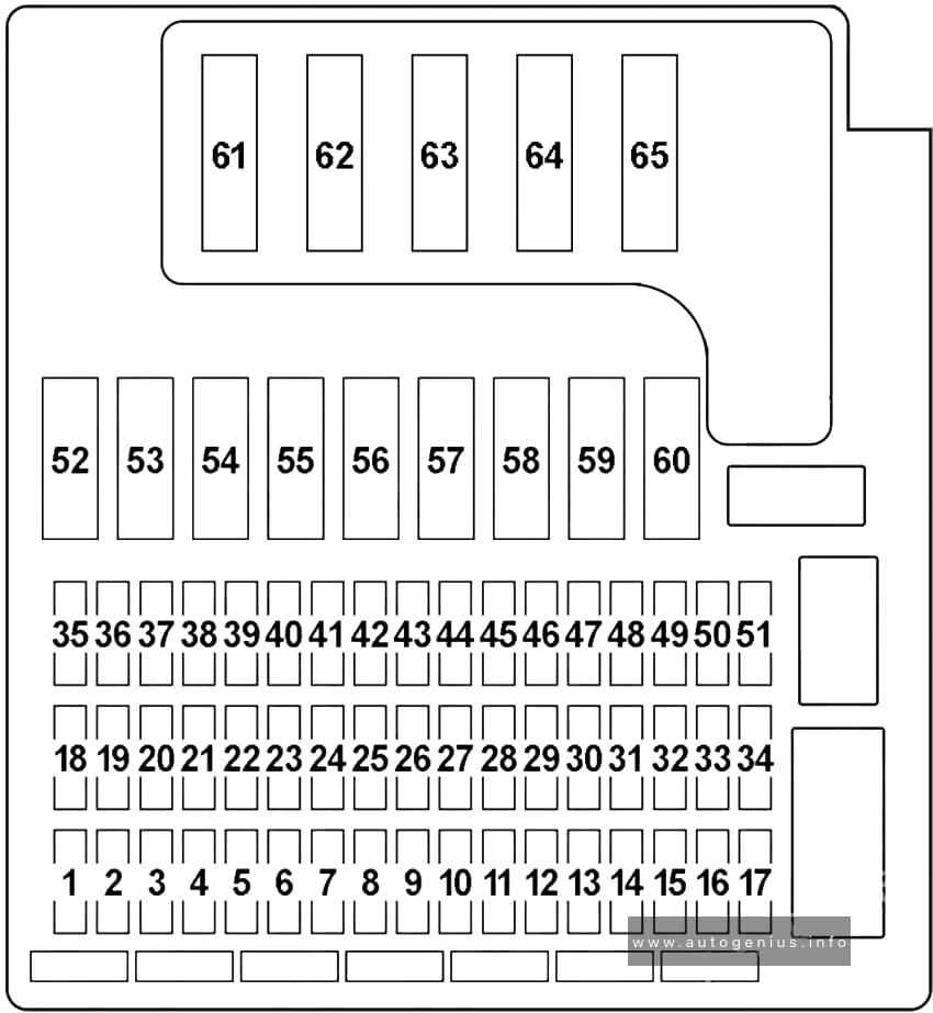
Assignment of the fuses in the passenger compartment
| № | Amps | Protected components |
|---|---|---|
| 1 | – | – |
| 2 | 10A | – |
| 3 | 30A | – |
| 4 | 30A | – |
| 5 | 15A | Front Cigar Lighter |
| 6 | 10A | Reversing Light Switch (Manual Transmission), Reversing Light Relay ((2003-2004) – Automatic Transmission, SMG) |
| 7 | 5A | Steering Angle Sensor DSC, “Sport” Button, Dynamic Stability Control (DSC) |
| 8 | 5A | Driver’s Door Module, Park Distance Control (PDC), Cigar Lighter Relay |
| 9 | 7.5A | 2003-2004: Oil Level Sensor, Transmission Control (Automatic Transmission), Sequential Manual Transmission (SMG). 2005-2008: Data Link Connector (OBD II), Integrated Supply Module (IVM (N52)) |
| 10 | 5A | 2005-2008: General Module Control Unit, Auxiliary Water Pump, Electronic Vehicle Immobilizer (EWS) |
| 11 | 25A | General Module Control Unit |
| 12 | 5A | General Module Control Unit, Electronic Vehicle Immobilizer (EWS), Centre Console Switch Centre, Instrument Cluster Control Unit |
| 13 | 5A | 2003-2005: Safety and Information Module, Seat Occupancy Recognition. 2006-2008: Rain/Headlight Sensor, Volume Spring |
| 14 | 5A | Secondary Air Pump Relay, Light Switch Cluster, Clutch Switch Module, Brake Light Switch |
| 15 | 30A | 2003-2005: Passenger’s Seat Adjustment Switch (LHD), Driver’s Seat Memory (RHD). 2006-2008: Passenger’s Seat Adjustment Switch |
| 16 | 25A | Centre Console Switch Center |
| 17 | – | – |
| 18 | – | – |
| 19 | 20A | Fuel Pump Relay |
| 20 | 20A/30A | Rear Window Defogger Relay (2003-2005 – 20A; 2006-2008 – 30A) |
| 21 | 5A | Heated Spray Nozzles Thermal Switch (2003-2004), Passenger’s Side Outside Mirror, Steering Column Switch (Cruise Control (2006-2008)) |
| 22 | 5A | Heating/Air Conditioning System, Electronic Power Steering (EPS) |
| 23 | 5A | Light Switch Cluster, Instrument Cluster Control Unit |
| 24 | 5A | Instrument Cluster Control Unit, Data Link Connector (OBD II), Steering Angle Sensor DSC, Gear Indicator Lighting (USA), Auxiliary Water Pump (S54) |
| 25 | 5A | Electrochromic Interior Rear View Mirror, Digital Motor Electronics (DME) Control Unit, Terminal 15 Power-Saving Relay, Rear Window Defogger Relay |
| 26 | 30A | General Module Control Unit |
| 27 | 5A | Outside Mirror Fold-in |
| 28 | 5A | 2003-2005: Steering Column Switch (Cruise Control), Rain/Headlight Sensor, Volume Spring. 2006-2008: Crash Safety Module, Airbag Indicator Light, Seat Occupancy Recognition |
| 29 | 30A | 2003-2005: Driver’s Seat Memory (LHD), Passenger’s Seat Adjustment Switch (RHD). 2006-2008: Driver’s Seat Memory |
| 30 | 5A/7.5A | 2003-2005 (7.5A): Horn for Antitheft Alarm System, Tilt Sensor, Interior Movement Detector, Electrochromic Interior Rear View Mirror. 2006-2008 (5A): Dynamic Stability Control (DSC) |
| 31 | 20A | Roadster: Convertible Top Module |
| 32 | 7.5A | 2003-2005: Sequential Manual Transmission (SMG). 2006-2008: Digital Motor Electronics (DME) Control Unit |
| 33 | 10A | Fuel Pump Relay, Secondary Air Pump Relay, E-Box Fan, Diagnostic Module for Fuel Tank Leakage (2003-2004) |
| 34 | – | – |
| 35 | – | – |
| 36 | 15A | Front Fog Lights Relay |
| 37 | 15A | Horn Relay |
| 38 | 30A | Wiper Relay №1 & 2 |
| 39 | 7.5A | 2003-2005: Heating/Air Conditioning System. 2006-2008: Heating/Air Conditioning System, Siren and Tilt Alarm Sensor, Interior Movement Detector, Electrochromic Interior Rear View Mirror |
| 40 | 30A | Headlight Washer Pump Relay |
| 41 | 5A | Driver’s Window Motor, Passenger’s Window Motor |
| 42 | 30A/40A | Dynamic Stability Control (DSC) (2003-2005 – 30A; 2006-2008 – 40A) |
| 43 | 20A/30A | Dynamic Stability Control (DSC) (2003-2005 – 30A; 2006-2008 – 20A) |
| 44 | 5A | 2006-2008: Fuel Pump Control (EKPS) |
| 45 | 10A | 2003-2005: Safety and Information Module. 2006-2008: Tyre Pressure Control (RDC) |
| 46 | 30A | General Module Control Unit |
| 47 | 7.5A | Navigation System, Radio, Basic Interface Telephone, Telephone Transceiver, Eject Box (2003-2005), Voice Control System |
| 48 | 7.5A | CD Changer |
| 49 | 10A | Central Information Display (CID), Navigation System, Video Module, Basic Interface Telephone (Japan), Compensator (except Japan), Eject Box (except Japan), Telephone Transceiver (except Japan), Voice Control System (except Japan) |
| 50 | 30A | Radio, Amplifier |
| 51 | – | – |
| 52 | – | – |
| 53 | – | – |
| 54 | 40A | Ignition Switch |
| 55 | 40A | Roadster: Convertible Top Relay №:1 & 2 |
| 56 | 50A | Secondary Air Pump Relay |
| 57 | 40A | Blower Output Stage |
| 58 | 40A | Ignition Switch |
| 59 | 40A | Light Switch Cluster |
| 60 | 40A | Light Switch Cluster |
| 61 | 60A | Electric Fan |
| 62 | – | – |
| 63 | 60A/80A | B+ Potential Distributor (2003-2005 – 80A; 2006-2008 – 60A). N52 (60A): B+ Potential Distributor, Integrated Supply Module (IVM), Fuel Injectors Relay, Digital Motor Electronics (DME) Control Unit, DME Relay, Variable Valve Gear Relay |
| 64 | 100A | Electronic Power Steering (EPS) |
| 65 | – | – |
WARNING: Terminal and harness assignments for individual connectors will vary depending on vehicle equipment level, model, and market.