Jaguar E-Pace (X540; 2017 – 2020) – fuse and relay box diagram
Year of production: 2017, 2018, 2019, 2020
The Jaguar E-Pace (X540), a subcompact luxury crossover SUV, has been in production since 2017. In this article, you’ll find fuse box diagrams for the 2017 through 2020 models, along with details on the locations of the fuse panels within the vehicle and explanations of each fuse’s function and layout.
Passenger compartment
Fuse box location
The fuse box is located below the glove box.
Fuse Box Diagrams
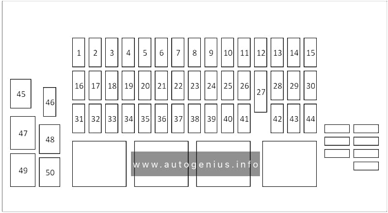
Assignment of the fuses in the passenger compartment fuse box
| № | Rating | Protected Component |
|---|---|---|
| 1 | 30A | Front passenger’s seat. |
| 2 | 30A | Driver’s seat. |
| 3 | 25A | Passenger’s door module. |
| 4 | 25A | Driver’s door module. |
| 5 | 5A | Keyless entry. |
| 6 | – | – |
| 7 | – | – |
| 8 | – | – |
| 9 | 5A | Tire Pressure Monitoring System (TPMS). |
| 10 | 5A | Battery back-up sounder. |
| 11 | 5A | Instrument panel. |
| 12 | 20A | Fuel system. |
| 13 | 5A | Rear seats. |
| 14 | 5A | Vehicle immobiliser. |
| 15 | 5A | Steering wheel. |
| 16 | 20A | Keyless entry. |
| 17 | 5A | Brake pedal switch. |
| 18 | 20A | Front blind. |
| 19 | 20A | Front passenger’s heated or climate seat. |
| 20 | 5A | Mirror. Camera. |
| 21 | 5A | Blind spot monitor. |
| 22 | 5A | Camera. |
| 23 | – | – |
| 24 | 10A | 2021-2023: Head-Up Display (HUD) module. |
| 25 | 10A | Instrument panel. |
| 26 | 20A | Cigar lighter. |
| 27 | – | – |
| 28 | 10A | Head-Up Display (HUD) and cooling fan. |
| 29 | 5A | Adaptive cruise control. |
| 30 | 20A | Driver’s heated and climate seat control. |
| 31 | 5A | Powered tailgate. |
| 32 | 5A | Driver door module. |
| 33 | 10A | Audio amplifier. |
| 34 | 15A | Infotainment system. |
| 35 | 15A | Infotainment system. |
| 36 | 10A | Audio video output. |
| 37 | 15A | Seat switches and memory. |
| 38 | 20A | Cubby box auxiliary power socket. |
| 39 | – | – |
| 40 | – | – |
| 41 | 10A | Heated steering wheel. |
| 42 | 5A | Steering wheel. |
| 43 | 20A | Heating and ventilation system. |
| 44 | – | – |
| 45 | 40A | Body control module. |
| 46 | – | – |
| 47 | 40A | Body control module. |
| 48 | – | – |
| 49 | 40A | Infotainment system amplifier. |
| 50 | 20A | Amplifier module. |
Engine Compartment Fuse Box
Fuse Box Diagrams

Assignment of the fuses in the engine compartment fuse box
| № | Rating | Protected Component |
|---|---|---|
| 1 | 30A | Engine control module. |
| 2 | 5A | Electrical power management. |
| 3 | 80A | Electric Power Assisted Steering System (EPAS). Engine management system. |
| 4 | 60A | Glow plugs (diesel only). |
| 5 | 100A | Engine cooling. |
| 6 | 15A | Engine management system. |
| 7 | 15A | Engine management system. |
| 8 | 15A | Engine management system. |
| 9 | 10A | Engine management system. |
| 10 | 5A | Fuel pump. |
| 11 | 10A | Engine management system. |
| 12 | 10A | Engine management system. |
| 13 | – | – |
| 14 | 10A | Engine cooling / Engine management system. |
| 15 | 40A | Engine management system. |
| 16 | 100A | Auxiliary heater. |
| 17 | 60A | Passenger compartment fuse box. |
| 18 | 60A | Passenger compartment fuse box. |
| 19 | 60A | Loadspace fuse box. |
| 20 | 60A | Loadspace fuse box. |
| 21 | 60A | Electrical power management. |
| 22 | 30A | Front windscreen wipers. |
| 23 | 40A | Passenger compartment fuse box. |
| 24 | 40A | Starter motor (diesel automatic only). |
| 25 | 40A | Anti-lock Braking System (ABS). |
| 26 | 40A | Anti-lock Braking System (ABS). |
| 27 | 40A | Passenger compartment fuse box. |
| 28 | 40A | Heater blower motor. |
| 29 | 30A | Electric trailer brake (Australia only). |
| 30 | 15A | Spare. |
| 31 | 15A | Horns. |
| 32 | 10A | Spare. |
| 33 | 5A | Horn. Heated windscreen. Fuel pump. |
| 34 | 40A | Left-side heated windscreen. |
| 35 | 40A | Right-side heated windscreen. |
| 36 | 5A | Engine management system. Air Conditioning (A/C). |
| 37 | 20A | Fuel pump. |
| 38 | 15A | Transmission control module. |
| 39 | 10A | Front fog lights. |
| 40 | 20A | Right-side headlight. |
| 41 | 20A | Left-side headlight. |
| 42 | – | – |
| 43 | – | – |
| 44 | – | – |
| 45 | – | – |
Luggage Compartment Fuse Box
Fuse Box Diagrams

Assignment of the fuses in the luggage compartment fuse box
| № | Rating | Protected Component |
|---|---|---|
| 1 | 15A | Rear wiper. |
| 2 | 20A | Deployable sidesteps. |
| 3 | 5A | Telematics. |
| 4 | 5A | Fuel Burning Heater (FBH). |
| 5 | 10A/25A | Fuel pump. |
| 6 | 30A | Power tailgate. |
| 7 | – | – |
| 8 | – | – |
| 9 | – | Battery spare. |
| 10 | – | – |
| 11 | 25A | Right-side rear door module. |
| 12 | 20A | Trailer. |
| 13 | 5A | All Wheel Drive (AWD). |
| 14 | 25A | Left-side rear door module. |
| 15 | – | – |
| 16 | – | – |
| 17 | – | – |
| 18 | – | – |
| 19 | 30A | Driveline. |
| 20 | – | – |
| 21 | 20A | Accessory socket. |
| 22 | – | – |
| 23 | – | – |
| 24 | 5A | Wade sensing. |
| 25 | 5A | Vehicle battery. |
| 26 | 20A | Rear heated seat module. |
| 27 | 5A | Windows. |
| 28 | 5A | Vehicle diagnostics. |
| 29 | – | – |
| 30 | – | – |
| 31 | – | – |
| 32 | – | – |
| 33 | 20A | Trailer socket. |
| 34 | 10A | Chassis control module. |
| 35 | 30A | Driveline. |
| 36 | 20A | Fuel pump. |
| 37 | – | – |
| 38 | 5A | Fan spare. |
| 39 | 20A | Rear control spare. |
| 40 | 10A | USB charger. |
| 41 | 20A | Right-side heated rear seat. |
| 42 | 20A | Rear console accessory socket. |
| 43 | – | – |
| 44 | 30A | Heated rear screen. |
| 45 | – | – |
| 46 | – | – |
| 47 | 30A | Driveline. |
| 48 | 30A | Deployable towbar. |
| 49 | – | – |
| 50 | 25A | Heater. |
WARNING: Terminal and harness assignments for individual connectors will vary depending on vehicle equipment level, model, and market.