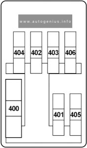
MG eHS (2020 – 2023) – fuse and relay box diagram

MG eHS (2020 – 2023) – fuse and relay box diagram

Years of production: 2020, 2021, 2022, 2023


The MG eHS (also known as the HS PHEV), a compact plug-in hybrid crossover, has been available since 2020. This article provides fuse box diagrams for the 2020, 2021, 2022, and 2023 models, offers information on the locations of the fuse panels inside the vehicle, and explains the function of each fuse (fuse layout).

Passenger Compartment Fuse Box

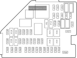
Fuse Box Diagram
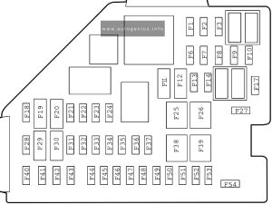
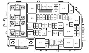
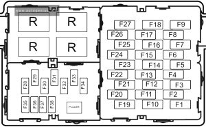
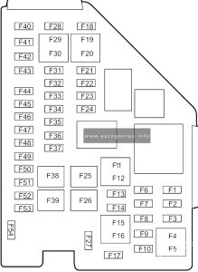
MG eHS (2020 - 2023) - fuse and relay box diagram - passenger compartment fuse box
MG eHS (2020 – 2023) – fuse and relay box diagram – passenger compartment fuse box


Assignment of the fuses in the passenger compartment

No. A Protected components
F1 10A Sensing Diagnostic Module (Airbag), Electronic Shifter Control Unit, TBOX, Instrument Pack, Body Control Module, Airbag Display Module
F2 7.5A Engine Control Module, Hybrid Control Unit
F3 5.0A Front View Control Module, Front Detection Radar
F6
F7 15A Towing Kit Connector Socket
F8 15A Front Power Socket
F9 5A USB Port
F10
F11 7.5A Mirror Heaters
F12 25A Rear Windscreen Heating
F13-F14
F17
F18 30A Rear Left Window Lift
F19 5A EPB Switch, PRND Display
F20 30A Rear Right Window Lift
F21 10A Front Right Seat Heating Relay
F22 5A Diagnostic Line Connector
F23 10A Front Left Seat Heating Relay
F24 10A Gateway
F25 40A KLR Relay
F26 30A Passenger Window lift
F27
F28 5A Passive Entry Passive Start Module, Backup Immobilizer Coil
F29 10A Gateway
F30 5A Driver Door Switch Pack, Rain Light Sensor
F31
F32 5A Ambient Light Control Module
F33 5A Sensing Diagnostic Module (Airbag)
F34 5A TBOX
F35 10A Radio Broadcasting Reception Module
F36 10A Electronic Steering Column Lock
F37 20A Driver Electric Adjust Seat Switch
F38 30A Driver Window Lift
F39 30A Blower
F40 15A Entertainment System
F41 5A Upper Console Switch
F42 10A AC Control Module
F43 5A Instrument Pack
F44 5A Rear Driving Assistance System
F45 30A Sunroof Motor
F46 5A Tyre Pressure Monitoring System
F47 30A Sunshade Motor
F48 20A Passenger Electric Adjust Seat
F49 5A Around View Module
F50
F51 30A Rear Windscreen Heating Relay, Exterior Mirrors Relay
F52 10A Headlamp, Interior Rear View Mirror, Headlamp Levelling Switch
F53 10A Electronic Shifter Control Unit
F54
F54

Engine Compartment Fuse Box

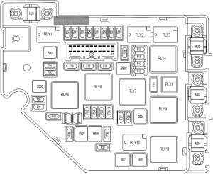
Fuse Box Diagram
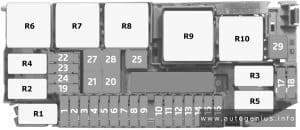
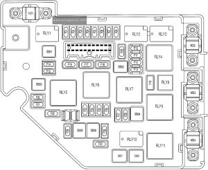
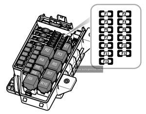
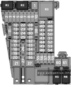
MG eHS (2020 - 2023) - fuse and relay box diagram - engine compartment fuse box
MG eHS (2020 – 2023) – fuse and relay box diagram – engine compartment fuse box


Assignment of the fuses in the engine compartment

No. A Protected components
F01 10A Right Headlamp Assembly
F02 10A Left Headlamp Assembly
F03 10A DC/DC Convertor
F04
F05 5A Electric Air Conditioning Compressor
F06
F07
F08 20A Power Electronic Box Coolant Pump
F09 10A Fuel Pump Relay, Lower Console Switch, Fuel Tank Isolation Diagnosis Module (Tank Leakage), Brake Pedal Switch
F10 20A Engine Control Module
F11 15A Intake Variable Camshaft Timing, Exhaust Variable Camshaft Timing, Upstream Lambda Sensor, Downstream Lambda Sensorv Canister Purge Valve
F12 20A Ignition Coil
F13 15A Waste Gate Control Valve, Dump Valve, Electronic Thermostat, Mass Air Flow Sensor
F14 25A Body Control Module
F15 10A Rear Washer Relay
F16 25A Body Control Module
F17 25A Body Control Module
F18 25A Body Control Module
F19 10A Front Fog Lamp Relay
F20 10A Front Washer Relay
F21 10A Engine Control Module
F22 10A Power Electronic Box
F23
F24
F25 30A Hybrid Control Unit
F26 25A Body Control Module
F27
F28 10A Engine Auxiliary Pump
F29 15A Horn
F30 10A Hybrid Control Unit
F31 25A Front Wiper Enable Relay
SB01 25A Body Control Module
SB02 60A Cooling Fan Low Speed Relay
SB03 40A EVP Relay
SB04 40A Cooling Fan
SB05 40A Stability Control System-Pump
SB06 40A Stability Control System-Valve
SB07
SB08 50A Cooling Fan Middle Speed Relay
MD1 200A Power Pump
MD2 100A Passenger Compartment Fusebox
MD3 80A Electric Power Steering Module
MD4 200A Luggage Compartment Fusebox


WARNING: Terminal and harness assignments for individual connectors will vary depending on vehicle equipment level, model, and market.

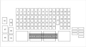
MG HS PHEV (2020 – 2023) – fuse and relay box diagram

MG HS PHEV (2020 – 2023) – fuse and relay box diagram

Years of production: 2020, 2021, 2022, 2023


The MG eHS (also known as the HS PHEV), a compact plug-in hybrid crossover, has been available since 2020. This article provides fuse box diagrams for the 2020, 2021, 2022, and 2023 models, offers information on the locations of the fuse panels inside the vehicle, and explains the function of each fuse (fuse layout).

Passenger Compartment Fuse Box

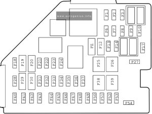
Fuse Box Diagram

MG HS PHEV (2020 - 2023) - fuse and relay box diagram - passenger compartment fuse box
MG HS PHEV (2020 – 2023) – fuse and relay box diagram – passenger compartment fuse box


Assignment of the fuses in the passenger compartment

No. A Protected components
F1 10A Sensing Diagnostic Module (Airbag), Electronic Shifter Control Unit, TBOX, Instrument Pack, Body Control Module, Airbag Display Module
F2 7.5A Engine Control Module, Hybrid Control Unit
F3 5.0A Front View Control Module, Front Detection Radar
F6
F7 15A Towing Kit Connector Socket
F8 15A Front Power Socket
F9 5A USB Port
F10
F11 7.5A Mirror Heaters
F12 25A Rear Windscreen Heating
F13-F14
F17
F18 30A Rear Left Window Lift
F19 5A EPB Switch, PRND Display
F20 30A Rear Right Window Lift
F21 10A Front Right Seat Heating Relay
F22 5A Diagnostic Line Connector
F23 10A Front Left Seat Heating Relay
F24 10A Gateway
F25 40A KLR Relay
F26 30A Passenger Window lift
F27
F28 5A Passive Entry Passive Start Module, Backup Immobilizer Coil
F29 10A Gateway
F30 5A Driver Door Switch Pack, Rain Light Sensor
F31
F32 5A Ambient Light Control Module
F33 5A Sensing Diagnostic Module (Airbag)
F34 5A TBOX
F35 10A Radio Broadcasting Reception Module
F36 10A Electronic Steering Column Lock
F37 20A Driver Electric Adjust Seat Switch
F38 30A Driver Window Lift
F39 30A Blower
F40 15A Entertainment System
F41 5A Upper Console Switch
F42 10A AC Control Module
F43 5A Instrument Pack
F44 5A Rear Driving Assistance System
F45 30A Sunroof Motor
F46 5A Tyre Pressure Monitoring System
F47 30A Sunshade Motor
F48 20A Passenger Electric Adjust Seat
F49 5A Around View Module
F50
F51 30A Rear Windscreen Heating Relay, Exterior Mirrors Relay
F52 10A Headlamp, Interior Rear View Mirror, Headlamp Levelling Switch
F53 10A Electronic Shifter Control Unit
F54
F54

Engine Compartment Fuse Box

Fuse Box Diagram

MG HS PHEV (2020 - 2023) - fuse and relay box diagram - engine compartment fuse box
MG HS PHEV (2020 – 2023) – fuse and relay box diagram – engine compartment fuse box


Assignment of the fuses in the engine compartment

No. A Protected components
F01 10A Right Headlamp Assembly
F02 10A Left Headlamp Assembly
F03 10A DC/DC Convertor
F04
F05 5A Electric Air Conditioning Compressor
F06
F07
F08 20A Power Electronic Box Coolant Pump
F09 10A Fuel Pump Relay, Lower Console Switch, Fuel Tank Isolation Diagnosis Module (Tank Leakage), Brake Pedal Switch
F10 20A Engine Control Module
F11 15A Intake Variable Camshaft Timing, Exhaust Variable Camshaft Timing, Upstream Lambda Sensor, Downstream Lambda Sensorv Canister Purge Valve
F12 20A Ignition Coil
F13 15A Waste Gate Control Valve, Dump Valve, Electronic Thermostat, Mass Air Flow Sensor
F14 25A Body Control Module
F15 10A Rear Washer Relay
F16 25A Body Control Module
F17 25A Body Control Module
F18 25A Body Control Module
F19 10A Front Fog Lamp Relay
F20 10A Front Washer Relay
F21 10A Engine Control Module
F22 10A Power Electronic Box
F23
F24
F25 30A Hybrid Control Unit
F26 25A Body Control Module
F27
F28 10A Engine Auxiliary Pump
F29 15A Horn
F30 10A Hybrid Control Unit
F31 25A Front Wiper Enable Relay
SB01 25A Body Control Module
SB02 60A Cooling Fan Low Speed Relay
SB03 40A EVP Relay
SB04 40A Cooling Fan
SB05 40A Stability Control System-Pump
SB06 40A Stability Control System-Valve
SB07
SB08 50A Cooling Fan Middle Speed Relay
MD1 200A Power Pump
MD2 100A Passenger Compartment Fusebox
MD3 80A Electric Power Steering Module
MD4 200A Luggage Compartment Fusebox


WARNING: Terminal and harness assignments for individual connectors will vary depending on vehicle equipment level, model, and market.
MG HS (2019 – 2023) – fuse and relay box diagram

MG HS (2019 – 2023) – fuse and relay box diagram

Years of production: 2019, 2020, 2021, 2022, 2023


The MG HS, a compact crossover, has been in production since 2019. This article features fuse box diagrams for the 2019, 2020, 2021, 2022, and 2023 models, provides details on the locations of the fuse panels inside the vehicle, and explains the function of each fuse (fuse layout).

Passenger Compartment Fuse Box

Fuse Box Diagram

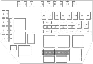
MG HS (2019 - 2023) - fuse and relay box diagram - passenger compartment fuse box
MG HS (2019 – 2023) – fuse and relay box diagram – passenger compartment fuse box


Assignment of the fuses in the passenger compartment

No. A Protected components
F1 10A Supplemental Restraint System Sensing and Diagnostic Module, DC-DC Converter, Communication Module, Shifter Control Unit, Instrument Pack, Body Control Module, SDM Auxiliary Display Module
F2 7.5A Transmission Control Module, Reverse Lamp Switch, Engine Control Module
F3 5A Front View Camera Module, Forward Detection Radar
F6
F7
F8 15A Front Console Power Socket
F9 5A USB Charging Port
F10
F11 7.5A Heated Exterior Rearview Mirror
F12 25A Heated Rear Window
F13
F14
F17
F18 30A Rear Left Window Regulator
F19 5A EPB Switch, Gear Display
F20 30A Rear Right Window Regulator
F21 10A Front Right Seat Heater Relay
F22 5A Data Link Connector
F23 10A Heated Front Left Seat
F24 10A Gateway
F25 30A KLR Relay
F26 30A Passenger Window Regulator
F27
F28 5A PEPS Control Unit, Spare Coil
F29 10A Gateway
F30 5A Driver Window Combination Switch, Rain/Light Sensor
F31
F32 5A Atmosphere Lamp Control Module
F33 5A Supplemental Restraint System Sensing and Diagnostic Module
F34 5A Communication Module
F35 10A Digital Audio Broadcasting (DAB) Module
F36 10A Electronic Steering Column Lock Control Module
F37 20A Driver Power Seat Adjustment
F38 30A Driver Window Regulator
F39 30A Blower
F40 15A Entertainment System
F41 5A Upper Centre Console Switch
F42 10A HVAC Control Module
F43 5A Instrument Pack
F44 5A Rear Driving Assist System
F45 30A Sunroof Motor
F46 5A Tyre Pressure Monitoring System
F47 30A Sunshade Motor
F48 20A Front Passenger Power Seat Adjustment
F49 30A Power Liftgate Control Module
F50
F51 30A Rear Window/Exterior Rearview Mirror Heater Relay
F52 10A KL15 Switch Relay
F53 20A Shifter Control Unit
F54

Engine Compartment Fuse Box

Fuse Box Diagram

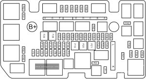
MG HS (2019 - 2023) - fuse and relay box diagram - engine compartment fuse box
MG HS (2019 – 2023) – fuse and relay box diagram – engine compartment fuse box


Assignment of the fuses in the engine compartment

No. A Protected components
F1
F2
F3 10A Front Fog Lamp
F4 25A Body Control Module
F5 25A Body Control Module
F6
F7 10A Engine Control Module
F8
F9 15A Horn
F10 5A Transmission Gear Shift Actuator
F11
F12 25A Body Control Module
F13 25A Body Control Module
F14
F15
F16
F17
F18
F19
F20 30A DC-DC Converter
F21 30A DC-DC Converter
F22
F23
F24 15A Rear Wiper Relay
F25 30A DC-DC Converter
F26 25A Body Control Module
F27 10A Windscreen/Rear Window Washer Relay
F28 25A Super Lock Relay
F29 25A Body Control Module
F30 25A Front Wiper Relay
F31
F32
F33
F34
F35
F36 10A A/C Compressor Relay
F37
F38 15A Fuel Pump Relay
F39 5A Crank Signal
F40
F41
F42
F43 5A DC-DC Converter Relay, Fuel Pump Relay, A/C Compressor Relay, Clutch Position Sensor, Brake Pedal Switch, Neutral Position Sensor, Cooling Fan Relay Box
F44 15A Electronic Thermostat, WT Valve – Intake, WT Valve – Exhaust, Upstream Oxygen Sensor, Downstream Oxygen Sensor, Canister Shut off Valve
F45 10A Engine Oil Control Valve, Canister Control Valve, Exhaust Gas Control Valve, Relief Valve
F46 15A Engine Control Module
F47 15A Ignition Coil, Air Flow Sensor
F48
F49 10A Right Headlamp
F50 10A Left Headlamp
F51
F52
F53
F54
F55
F56
MF1 A 80A Electric Power Steering Control Module
MF1 B 40A 7-speed Dual Clutch Transmission Control Module Relay
MF1 C 40A Dynamic Stability Control System (pump)
MF1 D 40A Dynamic Stability Control System (valve)
MF1 E
MF1 F 30A Starter Relay
MF1 G
MF1 H 50A Cooling Fan
MF2 K 100A Passenger Compartment Fuse Box
MF2 L 30A Electric Vacuum Pump
SB8 40 Blower relay


WARNING: Terminal and harness assignments for individual connectors will vary depending on vehicle equipment level, model, and market.
MG ZS  EV (2019 – 2021) – fuse and relay box diagram

MG ZS  EV (2019 – 2021) – fuse and relay box diagram

Year of production: 2019, 2020, 2021


The pre-facelift MG ZS EV, a subcompact electric crossover, was produced from 2019 to 2021. This article includes fuse box diagrams for the 2019, 2020, and 2021 models, provides details on the locations of the fuse panels inside the vehicle, and explains the function of each fuse (fuse layout).


Passenger Compartment Fuse Box

Fuse Box Location

The fuse panel is located below the glove box at the front passenger side.


Fuse Box Diagram

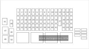
MG ZS EV (2019 - 2021) - fuse and relay box diagram - passenger compartment fuse box
MG ZS EV (2019 – 2021) – fuse and relay box diagram – passenger compartment fuse box


Assignment of the fuses in the passenger compartment

No.
А
Function
F1 5A Charging Plug Unlock Relay, Charging Plug Lock Relay
F2 10A Diagnostic Socket
F3 5A Charger, EVCC
F4 15A Front Wash Relay, Rear Wash Relay
F5 5A SDM
F6 5A HV PTC, ESS PTC
F7 10A ESS (High Voltage Battery)
F8 5A TPMS, EPB Switch
F9 5A VCU
F10 10A PACM
F11 5A PEPS
F12
F13 30A Driver Seat Adjust Switch
F14 5A IMMO Coil
F15 15A Front Power Socket
F16 5A Rear USB Charge Module, Master Light Switch, Headlamp Assembly
F17
F18 30A Rear Left Window Lift Switch
F19 30A Passenger Window Lift Switch
F20 30A Rear Right Window Lift Switch
F21 30A Driver Window Lift Motor
F22 10A Heated Mirrors
F23 25A Rear Windshield Assembly
F24 20A FICM, IFP, DAB
F25 15A ETC, ACFP
F26 5A Instrument Pack
F27 10A Driver Door Switch Pack, Master Light Switch
F28 5A RLS, Master Radar
F29 10A Gateway
F30 10A Gateway
F31 30A Sunroof ECU
F32 30A Sunroof ECU
F33 5A SCU
F34 10A ESCL
F35 15A Super Lock Relay
F36
F37
F38
F39
F40
F41
F42 30A EPB
F43 30A EPB
F44

Engine Compartment Fuse Box

Fuse Box Diagram

MG ZS EV (2019 - 2021) - fuse and relay box diagram - engine compartment fuse box
MG ZS EV (2019 – 2021) – fuse and relay box diagram – engine compartment fuse box


Assignment of the fuses in the engine compartment

Amps Function
FL1 I50A PEB
FL2 80A EPS
FL3 40A Cooling Fan Relay Pack
FL4 80A Passenger Compartment Fusebox Fuse F18, F19, F20, F21, F34, F35, F42, F43
FL5 80A Passenger Compartment Fusebox Fuse F1, F2, F3, F4, F5, F6, F7, F8, F9, F10, F11, F13, F14, F24, F25, F26, F27, F28, F29, F30, F31, F32, F33, HRW Relay
FL6 25A SCS Valve
FL7 30A Blower Motor, ETC
FL8 20A BCM
FL9 40A SCS Pump
FL10 30A BCM
FL11
FL12 20A BCM
FL13
FL14
FL15 30A KLR Relay
FL16
FL17 40A EVP Relay
F1
F2 15A PEB Water Pump, Cooling Fan Relay Pack
F3
F4
F5 10A EVAP
F6
F7 30A Wiper Enable Relay, Wiper Speed Relay
F8
F9
F10 10A Main Beam – RH
F11 10A Main Beam – LH
F12
F13 15A Horn Relay
F14
F15 5A Brake Pedal Switch
F16 15A Rear Wiper Relay
F17 15A ESS PWM Pump Relay
F18 5A SDM
F19 5A VCU
F20
F21 15A BCM
F22 10A Seat Heat Relay – LH
F23 10A Seat Heat Relay – RH
F24 10A PEB
F25 15A BCM
F26
F27 5A BCM, EVP Relay, Front Breath Lamp
F28
F29
F30 10A BCM, SCU, Instrument Pack, ADM, FVCM, Front Radar

WARNING: Terminal and harness assignments for individual connectors will vary depending on vehicle equipment level, model, and market.
MG MG3 (2019 – 2023) – fuse and relay box diagram

MG MG3 (2019 – 2023) – fuse and relay box diagram

Year of production: 2019, 2020, 2021, 2022, 2023


This article focuses on the second-generation MG MG3, following its second facelift, produced from 2018 to 2023. It includes fuse box diagrams for the 2019 through 2023 models, provides details on the locations of the fuse panels inside the vehicle, and explains the function of each fuse (fuse layout).


Location

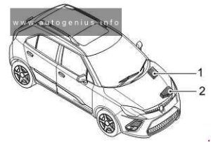
MG MG3 (2019 - 2023) - fuse and relay box location
MG MG3 (2019 – 2023) – fuse and relay box location


  1. Passenger Compartment Fuse Box (below the glove box at the front passenger side).
  2. Engine Compartment Fuse Box (at the left side of the Engine Compartment

Passenger Compartment Fuse Box

Fuse Box Location

The fuses are located below the glove box at the front passenger side.


Fuse Box Diagram

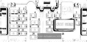
MG MG3 (2019 - 2023) - fuse and relay box diagram - passenger compartment fuse box
MG MG3 (2019 – 2023) – fuse and relay box diagram – passenger compartment fuse box


Assignment of the fuses in the passenger compartment

Amps Function
F1 20A Rear wiper relay, Rear wash relay
F2 15A Central lock motor (unlock)
F3 10A Diagnostic socket, Rearview mirror switch, Central door locking switch
F4 5A Steering angle sensor, Headlamp leveling, Master light switch
F5 10A Horn relay
F6 10A DC/DC, SCS control unit, Instrument pack, Body control module, TPMS, MTC, ETC, Daytime running lamp relay, Passenger airbag disable switch
F7 15A Super lock relay
F8 10A Airbag control module
F9 10A Fuel pump relay, Inertia switch
F10 5A Left side lamp, Left tail lamp, Interior switch illumination
F11 5A Interior lights
F12 5A Right side lamp, Right tail lamp, Rear license plate lamp, Interior switch illumination
F13 15A Brake pedal switch
F14 15A Central lock motor (lock)
F15 10A Reverse switch
F16 15A Front power socket
F17
F18 10A Blower relay, Body control module, Passenger compartment fuse box fuse F11, Rear wash relay, Instrument pack, Light sensor, Color radio, Radio
F19 7.5A Left brake lamp, High-mounted brake lamp
F20 25A Rear left window lift switch
F21 7.5A Right brake lamp
F22 25A Rear right window lift switch
F23 5A Body control module, Starter relay, Engine control module
F24 25A Front passenger window lift switch
F25 20A Rear window heating element
F26 25A Driver door combination switch
F27 10A Outside door mirror heating element
F28 20A Radio, Color radio, Entertainment system panel switch
F29
F30 10A MTC, ETC, ETC panel, TPMS
F31
F32 10A Instrument pack
F33
F34 10A DAB
F35
F36
F37
F38

Engine Compartment Fuse Box

Fuse Box Diagram

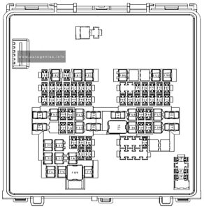
MG MG3 (2019 - 2023) - fuse and relay box diagram - engine compartment fuse box
MG MG3 (2019 – 2023) – fuse and relay box diagram – engine compartment fuse box


Assignment of the fuses in the engine compartment

Amps Function
F1 10A Right front dipped beam
F2 5A Downstream oxygen sensor, Intake camshaft solenoid valve, Exhaust camshaft solenoid valve
F3 10A Left front dipped beam
F4 10A A/C compressor clutch relay
F5 5A Engine control module
F6 5A A/C compressor clutch relay, Canister control valve, A/C medium pressure switch, Cooling fan relay box, Fuel pump relay, Starter relay, Clutch position switch, Start stop switch
F7 30A Front wiper enable relay, front wiper speed relay
F8 5A Upstream oxygen sensor
F9 15A Daytime running lamp
F10 10A Right front main beam, instrument pack main beam indicator
F11 10A Left front main beam
F12 30A Ignition coil, Fuel injector, Neutral position switch, Engine control module
F1 3
FL1 200A Alternator, fuse in engine compartment fuse box F4, FL11
FL2 40A SCS unit (pump)
FL3 40A Cooling fan relay box
FL4 60A Fuse in passenger compartment fuse box F20, F22, F24, F26
FL5 80A Fuse in passenger compartment fuse box F1, F3, F5, F7, F9, F25, F27, HRW relay
FL6 25A SCS system (valve)
FL7 50 A Ignition switch
FL8 25A Body control module
FL9 30A DC/DC, Fuse in passenger compartment fuse box F28, F30, F32, F34
FL10 25A Body control module
FL11 30A Blower relay
FL12 25A Body control module
FL13 30A Starter relay
FL14 25A Body control module
FL15 30A Main beam relay, Daytime running lamp relay, Position lamp relay
FL16

WARNING: Terminal and harness assignments for individual connectors will vary depending on vehicle equipment level, model, and market.
MG MG5 EV (2020 – 2024) –  fuse and relay box diagram

MG MG5 EV (2020 – 2024) –  fuse and relay box diagram

Year of production: 2020, 2021, 2022, 2023, 2024

The MG MG5 EV, a battery electric subcompact car, has been in production from 2020 to the present. This article provides fuse box diagrams for the 2020, 2021, 2022, 2023, and 2024 models, details the locations of the fuse panels inside the vehicle, and explains the function of each fuse (fuse layout)


Passenger compartment fuse box

Fuse Box Diagram

MG MG5 EV (2020 - 2024) - fuse and relay box diagram - passenger compartment fuse box
MG MG5 EV (2020 – 2024) – fuse and relay box diagram – passenger compartment fuse box


Assignment of the fuses in the passenger compartment

Amps Protected components
F1 15A Front Console Power Socket
F2 5A Interior Mirror, Rear Console USB Charging Ports
F3-F17
F18 5A 2020-2022: TBOX, Vehicle Control Unit, Sensing Diagnostic Module (Airbag), Shifter Control Unit, Instrument Pack.
2023-2023: Vehicle Control Unit, Sensing Diagnostic Module (Airbag), Shifter Control Unit, Instrument Pack, Front Detection Radar, Front View Control Module
F19 5A 2020-2022: AC Front Panel
2023-2024: Digital Audio Broadcasting Module
F20 10A AC Control Module
F21 10A Front Right Seat Heater
F22 5A Diagnostic Socket
F23 10A Front Left Seat Heater
F24 5A PEPS Control Module
F25
F26 30A 2020-2022: Front Left Window Lift, Rear Right Window Lift
2023-2024: Front Right Window Lift, Rear Right Window Lift
F27
F28 5A Backup Immobilizer Coil
F29 15A Entertainment System
F30 5A Instrument Pack
F31 5A EPB Switch
F32 5A 2020-2022: Rain Light Sensor
2023-2024: Driver Door Switch Pack, Tyre Pressure Monitoring System
F33 10A Sensing Diagnostic Module (Airbag)
F34 10A 2020-2022: Driver Door Switch Pack, Gateway
2023-2024: Gateway
F35
F36 15A 2023: Towing Device Reserved Interface
F37 25A Driver Electric Seat Adjustment
F38
F39 40A Blower
F40-F43
F44 5A 2020-2022: Radio Broadcasting Reception Module
2023-2024: 360 Around View Module
F45 10A 2020-2022: Electronic Steering Column Lock
F46 10A 2023-2024: Electronic Steering Column Lock
F47 5A High Voltage Electric Heater
F48
F49 5A TBOX
F50 10A Gateway
F51 5A 2020-2022: Shifter Control Unit, Tyre Pressure Monitoring System
2023-2024: Shifter Control Unit
F52 5A 2020-2022: Door Mirrors and Headlamp Levelling Adjustment Switch
F53 5A Pedestrian Alert Control Module
F54


Engine compartment fuse box

Fuse Box Diagram

MG MG5 EV (2020 - 2024) - fuse and relay box diagram - engine compartment fuse box
MG MG5 EV (2020 – 2024) – fuse and relay box diagram – engine compartment fuse box


Assignment of the fuses in the engine compartment

Amps Protected components
F1 On-board Network Terminal Resistance
F2 On-board Network Terminal Resistance
F3 30A Body Control Module
F4 20A Body Control Module
F5 15A Body Control Module
F6 5A Charging Plug Latch
F7 5A Vehicle Control Unit
F8 30A 2020-2022: Electric Parking Motor Control Unit
F8 5A 2023-2024: Electrical Battery Sensor
F9 15A Horn Relay, Horn
F10 10A 2023-2024: Electric Vehicle Communication Controller
F11 15A 2020-2022: High Voltage Battery Pack, Electric Vehicle Communication Controller, Battery Heater
2023-2024: High Voltage Battery Pack
F12-F24
F25 30A 2020-2022: Driver Door Switch Pack, Driver Window Lift, Rear Left Window Lift
2023-2024: Front Left Window Lift, Rear Left Window Lift
F26 30A Stability Control System (Valve)
F27 15A Windscreen Washer System
F28 10A Body Control Module
F29 20A Body Control Module
F30 25A Front Wiper System
F31 10A Power Electronic Box
F32 25A Body Control Module
F33 15A Superlock System
F34 15A Main relay, Power Electronic Box Water Pump, Brake Lamp Switch
F35 5A Combined Charging Unit
F36 5A 2020-2022: Electric Air Conditioning Compressor
2023-2024: Electric Air Conditioning Compressor, Charging Status Lamp
F37 10A 2020-2022: Main Beam Relay, Main beam
2023-2024: Daytime Running Lamp
F38 15A Rear Wiper System
F39 15A High-Voltage Battery Pack Coolant Pump
F40-F42
F43 7.5A Heated Exterior Rearview Mirror
F44 25A Heated Rear Window
F45
F46 5A 2020-2022: Door Mirrors and Headlamp Levelling Adjustment Switch, Manual Headlamp Levelling
2023-2024: Headlamp Levelling Adjustment Switch, Manual Headlamp Levelling
F47
F48 5A Charging Flap Motor
F49-F52
A 80A Electric Power Steering Module
B
C 40A Stability Control System (Pump)
D
E 40A 2023-2024: Electric Parking Motor Control Unit
F 30A Electrical Parking Brake Control Module
G 50A Cooling Fan
H 50A iBooster
M 150A Combined Charging Unit
L 30A Electronic Parking Brake Control Module
K 100A Passenger Compartment Fuse Box


WARNING: Terminal and harness assignments for individual connectors will vary depending on vehicle equipment level, model, and market.

Mazda CX-30 (2019 – 2023) –  fuse and relay box diagram

Mazda CX-30 (2019 – 2023) –  fuse and relay box diagram

Year of production: 2019, 2020, 2021, 2022, 2023


The Mazda CX-30, a compact crossover SUV, has been in production since 2019. In this article, you’ll find fuse box diagrams for the 2019, 2020, 2021, 2022 and 2023 models, along with information on the locations of the fuse panels inside the vehicle and details on each fuse’s function and layout.

Passenger compartment fuse box

Fuse Box Location

It is located behind the cover on the left side of the vehicle.

Mazda MX-30 (2019 - 2023) - fuse and relay box location - passenger compartment fuse box
Mazda MX-30 (2019 – 2023) – fuse and relay box location – passenger compartment fuse box


Fuse Box Diagram

Mazda MX-30 (2019 - 2023) - fuse and relay box location - passenger compartment fuse box
Mazda MX-30 (2019 – 2023) – fuse and relay box location – passenger compartment fuse box


Assignment of the fuses in the passenger compartment

Ampere Rating Protected Component
F1 Not Used
F2 Not Used
F3 Not Used
F4 15 A Power door locks (Driver)
F5 15 A Power door locks (Passenger)
F6 Not Used
F7 25 A Power liftgate
F8 Not Used
F9 30 A Power windows (Driver)
F10 30 A Power windows (Passenger)
F11 30 A Power seat (Driver)
F12 Not Used
F13 15 A Audio
F14 Not Used
F15 15 A Liftgate lock
F16 15 A Illumination
F17 10 A Brake lights
F18 10 A Reverse lights
F19 10 A Rear turn signal lights
F20 10 A Taillights
F21 10 A Taillights
F22 7.5 A Air bag
F23 Not Used

Engine compartment fuse box

Fuse Box Location

Open the fuse block cover by unhooking the tabs and lifting up on the cover.

Mazda MX-30 (2019 - 2023) - fuse and relay box location - engine compartment fuse box
Mazda MX-30 (2019 – 2023) – fuse and relay box location – engine compartment fuse box


Fuse Box Diagram

Mazda MX-30 (2019 - 2023) - fuse and relay box diagram - engine compartment fuse box
Mazda MX-30 (2019 – 2023) – fuse and relay box diagram – engine compartment fuse box


Assignment of the fuses in the engine compartment

Ampere Rating Protected Component
F1 Not Used
F2 20A Windshield wiper de-icer
F3 20A or 30A Not Used / Engine control system (30A)
F4 20A S-VT
F5 40A Engine control system
F6 20A Not Used
F7 15A or 20A Not Used / Fuel pump (20A)
F8 15A Engine control system
F9 15A Transmission control system
F10 15A Engine control system
F11 7.5A Air conditioner
F12 15A Engine control system
F13 15A Not Used
F14 20A Front seat warmer
F15 20A Not Used
F16 15A For protection of various circuits
F17 Not Used
F18 15A For protection of various circuits
F19 60A Power steering system
F20 15A Headlight (Left) 1
F21 15A Headlight (Right) 1
F22 15A Keyless system
F23 30A ABS, Dynamic stability control system
F24 15A Headlight (Left) 2
F25 15A Headlight (Right) 2
F26 7.5A On board diagnostics
F27 25A For protection of various circuits
F28 25A For protection of various circuits
F29 15A Windshield washer
F30 15A Accessory sockets
F31 15A Horn
F32 15A Headlights
F33 Not Used
F34 Not Used
F35 50A ABS, Dynamic stability control system
F36 Not Used
F37 40A Rear window defogger
F38 50A For protection of various circuits
F39 Not Used
F40 40A Air conditioner
F41 Not Used
F42 20A Windshield wipers
F43 30A Cooling fan
F44 30A Starter
F45 10A Engine control system
F46 15A Audio
F47 15A For protection of various circuits
F48 7.5A Air bag
F49 15A Instrument cluster
F50 15A Room light
F51 25A Audio
F52 10A Moonroof
F53 15A Engine control system
F54 15A i-ACTIVSENSE
F55 50A Not Used
F56 50A or 15A Not Used / Electric water pump (2022-2023) (15A)


WARNING: Terminal and harness assignments for individual connectors will vary depending on vehicle equipment level, model, and market.
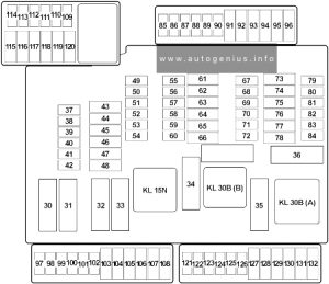
Mazda 3 (BP; 2019 – 2024) – fuse and relay  box diagram

Mazda 3 (BP; 2019 – 2024) – fuse and relay  box diagram

Year of production: 2019, 2020, 2021, 2022, 2023, 2024


This article focuses on the fourth-generation Mazda 3 (BP), produced from 2019 to the present. It includes fuse box diagrams for the 2019 through 2024 models, details the locations of the fuse panels within the vehicle, and provides information on the function and layout of each fuse and relay.


Passenger compartment fuse box

Fuse box location

It is located on the left side of the vehicle, behind the cover.

Mazda 3 (2019 - 2024) - fuse and relay box location - passenger compartment fuse box
Mazda 3 (2019 – 2024) – fuse and relay box location – passenger compartment fuse box


Fuse box diagram

Mazda 3 (2019 - 2024) - fuse and relay box diagram - passenger compartment fuse box
Mazda 3 (2019 – 2024) – fuse and relay box diagram – passenger compartment fuse box


Assignment of the fuses in the passenger compartment

Amp Rating Description
F1 Not Used
F2 Not Used
F3 Not Used
F4 15 A Power door locks (Driver)
F5 15 A Power door locks (Passenger)
F6 Not Used
F7 Not Used
F8 Not Used
F9 30 A Power windows (Driver)
F10 30 A Power windows (Passenger)
F11 30 A Power seat (Driver) (Some models)
F12 Not Used
F13 15 A Audio
F14 Not Used
F15 15 A Back door lock
F16 15 A Illumination
F17 10 A Brake lights
F18 10 A Back/Reverse lights
F19 10 A Rear turn signal lights
F20 10 A Taillights
F21 10 A Taillights
F22 7.5 A 2019-2020: Electric steering lock (Some models)
2021-2024: Air bag
F23 Not Used

Engine compartment fuse box

Fuse box location

Mazda 3 (2019 - 2024) - fuse and relay box location - engine compartment fuse box
Mazda 3 (2019 – 2024) – fuse and relay box location – engine compartment fuse box


Fuse box diagram

Mazda 3 (2019 - 2024) - fuse and relay box diagram - engine compartment fuse box
Mazda 3 (2019 – 2024) – fuse and relay box diagram – engine compartment fuse box


Assignment of the fuses in the engine compartment

Amp Rating Description
F1 Not Used
F2 20 A Windshield wiper de-icer (Some models)
F3 30 A Engine control system
F3 20 A Not Used
F4 20 A S-VT
F5 40 A Engine control system
F6 20 A Not Used
F7 15 A Not Used
F7 20 A Fuel pump
F8 15 A Engine control system
F9 15 A Transmission control system (Some models)
F10 15 A Engine control system
F11 7.5 A Air conditioner
F12 15 A Engine control system
F13 15 A Not Used
F14 20 A Front seat warmer (Some models)
F15 20 A Not Used
F16 15 A For protection of various circuits
F17 Not Used
F18 15 A 2019-2020: Accessory sockets
2021-2023: For protection of various circuits
2024: Not Used
F19 60 A Power steering system
F20 15 A Headlight (LH) 1
F21 15 A Headlight (RH) 1
F22 15 A 2019-2020: For protection of various circuits
2021-2024: Keyless system
F23 30 A ABS, Dynamic stability control system
F24 15 A Headlight (LH) 2
F25 15 A Headlight (RH) 2
F26 7.5 A On board diagnostics
F27 25 A For protection of various circuits
F28 25 A For protection of various circuits
F29 15 A Windscreen washer
F30 15 A Accessory sockets
F31 15 A Horn
F32 Not Used
F33 Not Used
F34 10 A 2019-2023: Not Used
2024: i-ACTIVSENSE
F35 50 A ABS, Dynamic stability control system
F36 Not Used
F37 40 A Rear window defogger
F38 50 A For protection of various circuits
F39 Not Used
F40 40 A Air conditioner
F41 Not Used
F42 20 A Windshield wipers
F43 30 A Cooling fan
F44 30 A 2019-2020: For protection of various circuits
2021-2024: Starter
F45 10 A Engine control system
F46 15 A Audio
F47 15 A For protection of various circuits
F48 7.5 A Air bag
F49 15 A Instrument cluster
F50 15 A Room lamp
F51 25 A Audio system
F52 10 A Moonroof (Some models)
F53 15 A Engine control system
F54 15 A i-ACTIVSENSE
F55 50 A Not Used
F56 50 A
15 A
Not Used
2021-2024: Electric water pump


WARNING: Terminal and harness assignments for individual connectors will vary depending on vehicle equipment level, model, and market.

Subaru Outback (2020 – 2021) – fuse and relay box diagram

Subaru Outback (2020 – 2021) – fuse and relay box diagram

Year of production: 2020, 2021


This article examines the seventh‑generation Subaru Legacy and the sixth‑generation Subaru Outback, produced from 2020 onward. You’ll find fuse box diagrams for the 2020 and 2021 models, guidance on locating the fuse panels within the vehicle, and a detailed overview of each fuse’s function and layout.


Passenger compartment fuse box

Fuse Box Location

It is located behind the cover below and to the left of the steering wheel.

Subaru Outback (2020 - 2021) - fuse and relay box location - passenger compartment
Subaru Outback (2020 – 2021) – fuse and relay box location – passenger compartment


Fuse Box Diagram

Subaru Outback (2020 - 2021) - fuse and relay box diagram - passenger compartment
Subaru Outback (2020 – 2021) – fuse and relay box diagram – passenger compartment


Assignment of fuses in the instrument panel (2020-2021)

Fuse Ampere rating [A] Circuit
1 Not Used
2 20 A CIGAR
3 7.5 A IG A-1
4 15 A AUDIO NAVI
5 10 A IG B-2
6 7.5 A METER IG (DCDC)
7 20 A 12V SOCKET
8 10 A A/C IG
9 7.5 A ACC
10 7.5 A IG B-1
11 7.5 A EYE SIGHT (DCDC)
12 Not Used
13 7.5 A IG A-3
14 Not Used
15 Not Used
16 7.5 A UNIT IG (DCDC)
17 7.5 A MIRROR ACC
18 Not Used
19 10 A IG A-2
20 10 A SRS AIRBAG
21 7.5 A A/C IG (DCDC)
22 10 A EYE SIGHT
23 7.5 A IGA-4
24 7.5 A A/C ACC (DCDC)
25 7.5 A UNIT +B (DCDC)
26 10 A BACK UP
27 15 A SEAT HTR R
28 20 A TRAIL R.FOG
29 Not Used
30 7.5 A BACK UP (DCDC)
31 7.5 A SMT (DCDC)
32 15 A MIRROR +B
33 7.5 A KEY SW A
34 Not Used
35 7.5 A ILLUMI (DCDC)
36 7.5 A KEY SW B
37 15 A UNIT +B1
38 7.5 A UNIT +B2

Engine compartment fuse box

Fuse Box Diagram

Subaru Outback (2020 - 2021) - fuse and relay box diagram - engine compartment
Subaru Outback (2020 – 2021) – fuse and relay box diagram – engine compartment


Assignment of fuses in the engine compartment (2020-2021)

Fuse Ampere rating [A] Power consumer
1 Not Used
2 7.5 A OBD
3 7.5 A STOP
4 10 A MB-B
5 7.5 A PU B/UP
6 30 A JB-B2
7 7.5 A M/B-IG1
8 7.5 A M/B-IG2
9 10 A M/B-IG3
10 7.5 A M/B-IG4
11 7.5 A HORN1
12 7.5 A HORN2
13 10 A TAIL
14 15 A HAZARD
15 20 A D/L
16 20 A F/P
17 Not Used
18 Not Used
19 10 A AVCS
20 15 A ETC
21 15 A TCU
22 7.5 A CVT SSR
23 10 A E/G2
24 15 A IG COIL
25 20 A O2 HTR
26 20 A DI
27 15 A E/G1
28 25 A MAIN FAN
29 15 A DEICER
30 30 A VDC SOL
31 15 A F-END
32 30 A F.WIP
33 25 A R.DEF
34 30 A BACKUP
35 20 A HTR
36 25 A SUB FAN
37 15 A R.WIP
38 20 A BLOWER
39 20 A BLOWER
40 10 A MB-A
41 Not Used
37 15 BLOWER
38 10 F.FOG RH
39 10 F.FOG LH
40
41 15 STRG/H
Spare fuses are located on the fusebox cover.


WARNING: Terminal and harness assignments for individual connectors will vary depending on vehicle equipment level, model, and market.
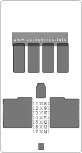
Subaru Legacy (2020 – 2021) – fuse and relay box diagram

Subaru Legacy (2020 – 2021) – fuse and relay box diagram

Year of production: 2020, 2021


This article examines the seventh‑generation Subaru Legacy and the sixth‑generation Subaru Outback, produced from 2020 onward. You’ll find fuse box diagrams for the 2020 and 2021 models, guidance on locating the fuse panels within the vehicle, and a detailed overview of each fuse’s function and layout.


Passenger compartment fuse box

Fuse Box Location

It is located behind the cover below and to the left of the steering wheel.

Subaru Legacy (2020 - 2021) - fuse and relay box location - passenger compartment
Subaru Legacy (2020 – 2021) – fuse and relay box location – passenger compartment


Fuse Box Diagram

Subaru Legacy (2020 - 2021) - fuse and relay box diagram - passenger compartment
Subaru Legacy (2020 – 2021) – fuse and relay box diagram – passenger compartment


Assignment of fuses in the instrument panel (2020-2021)

Fuse Ampere rating [A] Circuit
1 Not Used
2 20 A CIGAR
3 7.5 A IG A-1
4 15 A AUDIO NAVI
5 10 A IG B-2
6 7.5 A METER IG (DCDC)
7 20 A 12V SOCKET
8 10 A A/C IG
9 7.5 A ACC
10 7.5 A IG B-1
11 7.5 A EYE SIGHT (DCDC)
12 Not Used
13 7.5 A IG A-3
14 Not Used
15 Not Used
16 7.5 A UNIT IG (DCDC)
17 7.5 A MIRROR ACC
18 Not Used
19 10 A IG A-2
20 10 A SRS AIRBAG
21 7.5 A A/C IG (DCDC)
22 10 A EYE SIGHT
23 7.5 A IGA-4
24 7.5 A A/C ACC (DCDC)
25 7.5 A UNIT +B (DCDC)
26 10 A BACK UP
27 15 A SEAT HTR R
28 20 A TRAIL R.FOG
29 Not Used
30 7.5 A BACK UP (DCDC)
31 7.5 A SMT (DCDC)
32 15 A MIRROR +B
33 7.5 A KEY SW A
34 Not Used
35 7.5 A ILLUMI (DCDC)
36 7.5 A KEY SW B
37 15 A UNIT +B1
38 7.5 A UNIT +B2

Engine compartment fuse box

Fuse Box Diagram

Subaru Legacy (2020 - 2021) - fuse and relay box diagram - engine compartment
Subaru Legacy (2020 – 2021) – fuse and relay box diagram – engine compartment


Assignment of fuses in the engine compartment (2020-2021)

Fuse Ampere rating [A] Power consumer
1 Not Used
2 7.5 A OBD
3 7.5 A STOP
4 10 A MB-B
5 7.5 A PU B/UP
6 30 A JB-B2
7 7.5 A M/B-IG1
8 7.5 A M/B-IG2
9 10 A M/B-IG3
10 7.5 A M/B-IG4
11 7.5 A HORN1
12 7.5 A HORN2
13 10 A TAIL
14 15 A HAZARD
15 20 A D/L
16 20 A F/P
17 Not Used
18 Not Used
19 10 A AVCS
20 15 A ETC
21 15 A TCU
22 7.5 A CVT SSR
23 10 A E/G2
24 15 A IG COIL
25 20 A O2 HTR
26 20 A DI
27 15 A E/G1
28 25 A MAIN FAN
29 15 A DEICER
30 30 A VDC SOL
31 15 A F-END
32 30 A F.WIP
33 25 A R.DEF
34 30 A BACKUP
35 20 A HTR
36 25 A SUB FAN
37 15 A R.WIP
38 20 A BLOWER
39 20 A BLOWER
40 10 A MB-A
41 Not Used
37 15 BLOWER
38 10 F.FOG RH
39 10 F.FOG LH
40
41 15 STRG/H
Spare fuses are located on the fusebox cover.


WARNING: Terminal and harness assignments for individual connectors will vary depending on vehicle equipment level, model, and market.